PLC Programming Examples by Machine and Process Application
Worked PLC programming examples organized by the machine or process being controlled, with explicit I/O, state ownership, failure behavior, acceptance tests and target-system limits.
Reviewed and updated August 29, 2026
A useful PLC programming example is not just a rung or code fragment. It connects a stated machine or process requirement to named inputs and outputs, an execution model, command and feedback states, abnormal cases, and an acceptance test. The equipment changes between a conveyor, pump station, tank, robot cell, air handler and batch mixer; the reusable engineering pattern is request → permissive → command → physical feedback → timeout or completion evidence.
This guide provides six worked, platform-neutral application examples and a method for translating them into the selected controller. The code fragments show control intent rather than a downloadable vendor project. They do not establish machine safety, electrical design, process sizing, regulatory compliance or target-runtime behavior.
At a glance:
- Use a state machine when only one operating state should own outputs and legal transitions.
- Separate command from feedback: a true output bit does not prove a motor, valve, damper or robot moved.
- Give every physical transition a time expectation and failure response.
- Define Manual, Auto, Out of Service and maintenance ownership instead of scattering mode checks through unrelated rungs.
- Test simultaneous conditions, held requests, bad quality, failed feedback, restart and communications loss—not only the normal cycle.
- Treat browser simulation as logic evidence; repeat compiler, task, I/O, timing, retentivity and safety tests on the approved target.
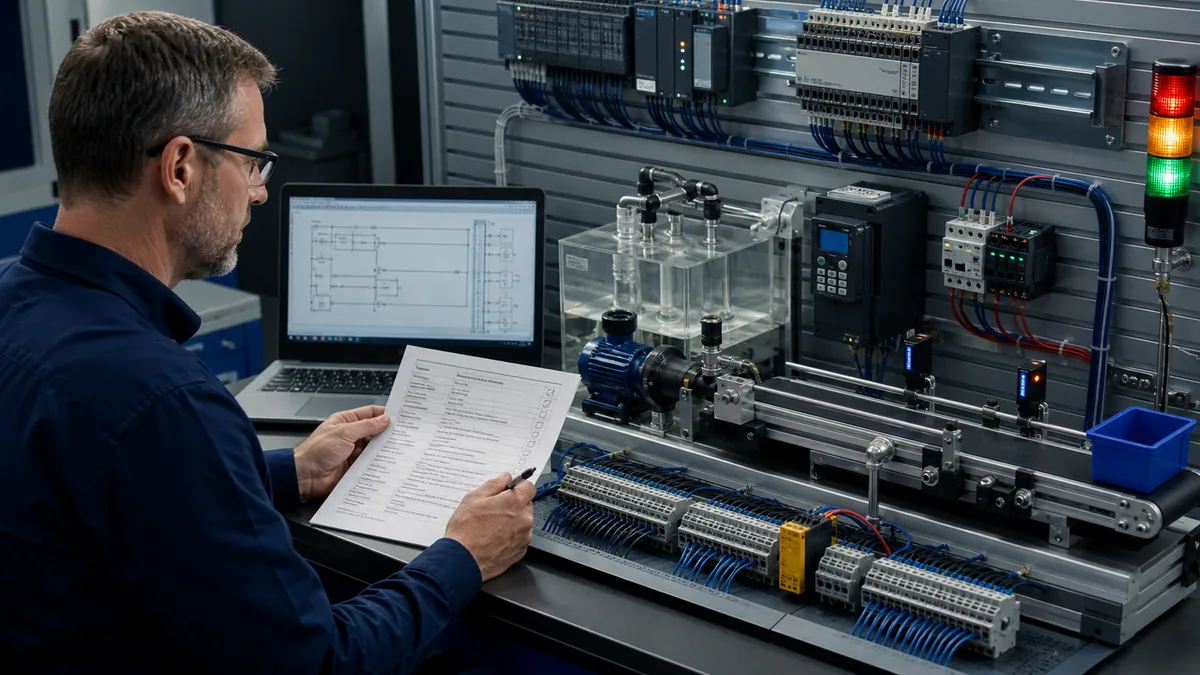
Diagnostic answer map for PLC programming examples
The phrase “PLC example program” covers several different needs. Use this map before choosing a listing to copy or a simulator to open.
| User question | Direct answer | Evidence that closes the question |
|---|---|---|
| What are common PLC program examples? | Motor control, conveyor zones, pump alternation, tank level control, robot handshakes, HVAC sequences and batch phases are transferable examples. | Requirement, I/O list, states, code and acceptance cases |
| What makes an example industrial rather than academic? | It distinguishes request, permissive, command and feedback; handles timeouts, modes, restart and diagnostics; and states what remains outside the PLC listing. | Failure matrix plus physical/target boundary |
| Which example should a beginner build first? | Start with stop-dominant motor control, then a two-state tank or one conveyor zone before adding multi-step coordination. | Graded normal, held-input and fault cases |
| Should I download a PDF or project file? | A file helps only when its controller, firmware, libraries, task, I/O and assumptions match the learning goal. Preserve an editable requirement and test matrix beside it. | Version record, compile result and target rerun |
| Can the same logic run on Siemens, Rockwell, CODESYS or Mitsubishi? | The control pattern can transfer; declarations, instructions, timer/edge semantics, project structure and restart behavior need translation. | Same acceptance matrix run on each target |
| How do I troubleshoot a real application? | Trace one boundary at a time: request, permission, owner/state, command, channel, field voltage/current, actuator response and returned feedback. | Timestamped scan/trace and physical measurement |
| Where can I practise without hardware? | A browser or vendor simulator can prove selected logic behavior. It cannot prove field wiring, target scheduling, mechanical dynamics or a safety function. | Simulator grade plus separate target test record |
| Does this page replace the detailed application pages? | No. This pillar owns the cross-application method and compact worked patterns; linked pages own full conveyor, HVAC, water, PID and machine-specific implementation depth. | Explicit internal-link ownership |
From process requirement to PLC program
Start with a control narrative, not an instruction palette. A good narrative states what starts the operation, what must already be true, what is commanded, what proves success, how long success may take, what stops or aborts the operation, and what the operator can do afterward.
| Design layer | Conveyor example | Pump example | Review question |
|---|---|---|---|
| Request | Transfer one carton downstream | Maintain wet-well level automatically | Is it a pulse, held level, setpoint or scheduled demand? |
| Permissive | Guarded machine available; downstream can receive | Auto enabled; no low-low trip; discharge path available | Which conditions inhibit start, and which remove a running command? |
| Command | Zone motor run output | Selected pump run/speed request | Is there one software owner and one mapped physical output? |
| Feedback | Drive running and carton reaches next sensor | Drive running plus changing level/flow where required | What physical evidence distinguishes action from command? |
| Timing | Carton must clear within transfer window | Pump must prove within start window | Where does timing start, pause, reset and expire? |
| Completion | Receiving zone owns the carton | Level returns below stop threshold | Is completion latched, acknowledged or immediately reusable? |
| Failure | Jam, drive fault, downstream unavailable | Fail-to-start, high-high level, no level response | What command is removed, what state is entered and what diagnosis persists? |
| Recovery | Clear obstruction under approved procedure, then reset | Select healthy standby, investigate failed unit, controlled reset | What conditions make reset acceptable without causing automatic motion? |
Build the artifacts in this order:
- Problem and boundary. Name the physical process, ordinary control responsibility, safety boundary, external systems and excluded functions.
- I/O and tag contract. Give every signal a source, engineering meaning, healthy state, update expectation and quality/status behavior.
- Modes and ownership. Define who may command in Off, Manual, Auto, maintenance and degraded operation.
- State or sequence model. List states, legal transitions, priorities, timeouts and outputs owned in each state.
- Code and configuration. Implement the model in the supported language, libraries and task.
- Acceptance matrix. Test the normal path, edges, failures, reset, restart and communications behavior.
- Target evidence. Record compiler/runtime versions, task timing, I/O checks, traces and deviations.
Pattern selector: choose the control structure from the application
| Application shape | Useful primary pattern | Supporting patterns | Common mistake |
|---|---|---|---|
| One motor or valve | Stop-dominant request plus explicit feedback supervision | Permissive chain, start/stop timeout, fault latch | Treating output command as proof |
| Several conveyor zones | Per-zone state plus upstream/downstream handshake | Edge capture, tracking, jam timeout | One global run bit with hidden ownership |
| Pump station | Equipment objects plus duty selection | Hysteresis, alternation, failover, runtime accounting | Alternating into an unavailable pump |
| Analog tank/flow loop | Validated scaling plus mode-aware PID/output composition | Range/quality checks, independent high/low response | Running control on bad or stale measurement |
| Robot or packaged machine | Explicit request/acknowledge/busy/complete handshake | Sequence number, timeout, mode/status | One-cycle pulses that the other controller misses |
| HVAC air handler | Written sequence of operation plus point/proof model | Schedules, resets, alarms, fault detection | Enabling heating/cooling/fan without proof and limits |
| Batch or recipe | Equipment modules and procedural phases | Hold/abort/restart, parameter validation, record context | Interleaving recipe, equipment and I/O code |
| Repeated calculations | Bounded array/loop or reusable function block | Validity flags, index limits, execution-time measurement | Variable work that overruns the task |
Example 1: three-zone conveyor transfer with jam detection
Problem and I/O contract
A carton waits at Zone 1. Zone 2 may accept it only when Zone 2 is empty, its drive is available, ordinary process permissives are healthy and the downstream transfer is not blocked. Once transfer starts, the Zone 1 command remains on until the carton leaves its sensor and is detected in Zone 2. Failure to reach the receiving sensor within the validated transfer window raises a jam fault and removes ordinary motion commands.
| Tag | Type/source | Meaning | Required abnormal test |
|---|---|---|---|
Z1_PartPresent |
Digital input | Carton occupies the sending zone | Stuck true, chatter, carton removed manually |
Z2_PartPresent |
Digital input | Receiving zone is occupied | Already occupied, delayed arrival, stuck false |
Z1_DriveReady |
Network/input | Drive can accept an ordinary run command | Ready drops during transfer |
Z1_DriveRunning |
Network/input | Drive reports running | Command true but feedback absent |
DownstreamAvailable |
Logic/handshake | Next owner can receive product | Drops before and during transfer |
TransferRequest |
Sequence bit | One transfer is requested | Held request and repeated edge |
Z1_RunCommand |
Digital/network output | Ordinary run request to Zone 1 drive | Verify one writer and off in fault |
TransferState |
Enum/internal | Idle, Starting, Transferring, Complete or Faulted | Invalid/corrupted state where testable |
TransferTimer |
Timer instance | Supervises physical movement | Exact expiration boundary |
JamFault |
Diagnostic | Transfer did not complete as required | Latch, acknowledgement and reset rejection |
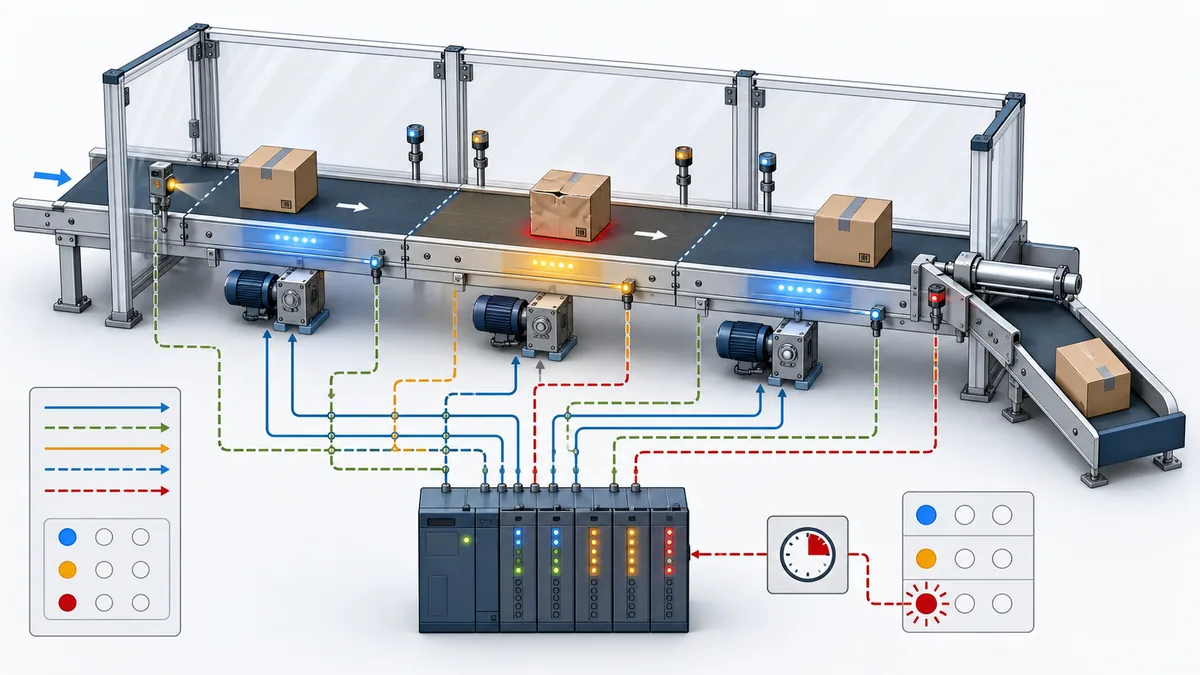
Platform-neutral state logic
The following Structured Text expresses the sequence intent. Timer and edge syntax must be translated to the target platform. The safety system is outside this ordinary-control example.
Z1_RunCommand := FALSE;
TransferTimer(IN := TransferState = TRANSFERRING, PT := TransferLimit);

CASE TransferState OF
    IDLE:
        IF TransferRequest AND Z1_PartPresent
           AND NOT Z2_PartPresent
           AND Z1_DriveReady AND DownstreamAvailable THEN
            TransferState := STARTING;
        END_IF;

    STARTING:
        Z1_RunCommand := Z1_DriveReady AND DownstreamAvailable;
        IF NOT DownstreamAvailable THEN
            TransferState := FAULTED;
            FaultCode := DOWNSTREAM_LOST;
        ELSIF Z1_DriveRunning THEN
            TransferState := TRANSFERRING;
        ELSIF StartTimer.Q THEN
            TransferState := FAULTED;
            FaultCode := DRIVE_FAILED_TO_START;
        END_IF;

    TRANSFERRING:
        Z1_RunCommand := Z1_DriveReady AND DownstreamAvailable;
        IF Z2_PartPresent THEN
            TransferState := COMPLETE;
        ELSIF TransferTimer.Q THEN
            TransferState := FAULTED;
            FaultCode := TRANSFER_TIMEOUT;
        END_IF;

    COMPLETE:
        IF NOT TransferRequest THEN
            TransferState := IDLE;
        END_IF;

    FAULTED:
        IF ResetEdge AND NOT Z1_DriveRunning AND ResetConditionsHealthy THEN
            FaultCode := NO_FAULT;
            TransferState := IDLE;
        END_IF;
END_CASE;
The example deliberately does not infer carton identity from one sensor edge. Real tracking may need encoder position, zone occupancy arbitration, a sequence identifier, reject verification or reconciliation after a manual removal. A timeout value must be derived from belt speed, distance, acceleration, product variation and tested margin—not copied from a generic tutorial.
Conveyor acceptance cases
| Case | Stimulus | Expected state and command | Evidence |
|---|---|---|---|
| Normal transfer | Valid request; receiving zone clear; drive proves; carton arrives | Idle → Starting → Transferring → Complete; command on only while needed | State/command/feedback trace |
| Drive fails to start | Command issued; running feedback absent | Faulted; ordinary command removed; start-failure code retained | Timer and drive status |
| Downstream blocks | Availability drops before start | Remain Idle; no command | Handshake and state trace |
| Downstream drops mid-transfer | Availability drops while carton moving | Defined controlled stop/fault according to mechanical risk assessment | Transition priority and physical result |
| Carton never arrives | Sending sensor clears but receiving sensor stays false | Transfer-timeout fault | Sensor trace and timer expiration |
| Held request | Request remains true after completion | No duplicate transfer until acknowledgement/reset condition | Request/complete arbitration |
| Restart | Controller mode/power cycle in each active state | Documented non-retained/retained recovery; no unintended motion | Restart test record |
Use the dedicated conveyor programming guide for accumulation, tracking, speed coordination and full implementation depth.
Example 2: lead-lag-standby pump station
Control objective and availability
A three-pump wet well should hold level inside an operating band while distributing service among available pumps. The selected lead pump starts at the lead-start threshold. A lag pump joins at a higher threshold or when inflow exceeds lead capacity. A third unit remains standby or replaces a unit that fails to prove. Low-low level removes ordinary pump demand to protect against dry running when that response matches the process design; high-high level creates an urgent process alarm and may require a separately engineered response.
Do not reduce availability to NOT Fault. A pump can be unavailable because it is in Local, isolated, under maintenance, inhibited, communications-bad, not ready, tripped, or outside a permitted restart interval.
| Pump property | Meaning | Selection rule |
|---|---|---|
Available |
Auto ownership, required communications, ready feedback and no active exclusion | Only available units enter the candidate set |
RunningProved |
Starter/drive feedback received inside the start window | A command without proof is not service |
Runtime |
Approved accumulated service metric | May inform rotation but must have known reset/source behavior |
Starts |
Count of accepted start cycles | Avoid an algorithm that creates excessive cycling |
DutyRank |
Current lead/lag/standby assignment | Change only at a defined rotation boundary |
FailedToStart |
Commanded unit did not prove | Remove it from the current attempt and apply the approved failover policy |
OutOfService |
Authorized operational/maintenance exclusion | Cannot be overridden by automatic rotation |
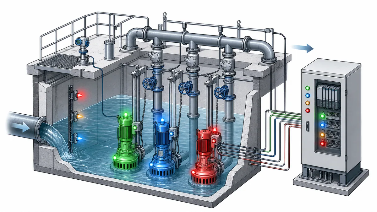
Selection and failover algorithm
Run selection in explicit stages:
- Build a candidate set from units that are authorized and available.
- Apply the stored duty order only to that candidate set.
- Calculate demand stages from a validated level measurement and independent limit states.
- Issue one command per selected unit through its equipment object.
- Supervise start proof, continued proof and process response.
- If a selected unit fails, latch the diagnosis, remove it from the current candidates and decide whether automatic standby start is permitted.
- Rotate duty at a predictable boundary such as a completed cycle—not on every scan and not merely when runtime values cross.
| Pump-station case | Expected result |
|---|---|
| Lead threshold reached | One available lead candidate commanded; start proof supervised |
| Lag threshold reached while lead proven | Second available candidate commanded; both proofs visible |
| Lead fails to prove | Lead command removed/latches failure; standby policy applied only if allowed |
| Level transmitter bad/stale | PID/staging does not continue as though value were healthy; approved fallback or shutdown applies |
| High-high independent input | Urgent alarm and defined response; disagreement with analog level is diagnosable |
| All units unavailable | No phantom “running” status; capacity-unavailable alarm contains unit reasons |
| Communications restored | No automatic start unless the restart/mode requirement permits it |
The Siemens pump-control application example demonstrates a version-scoped pump switchover example. It is evidence that vendors publish application packages, not proof that its hardware, communications architecture or fixed timing suits another station. The US EPA's smart sewer technology overview describes real-time level/flow sensing, supervisory systems and automated gates, weirs, valves and pumps at the sector level.
Example 3: tank level control with analog quality and independent limits
A continuous tank example adds analog scaling and a control loop to the discrete state model. The PLC receives a level transmitter, validates signal quality and range, converts the raw value to engineering units, compares it with operating limits, and modulates an inlet valve or outlet pump. Independent high-high and low-low switches can provide separate diagnostic or protective evidence where the process design requires them.
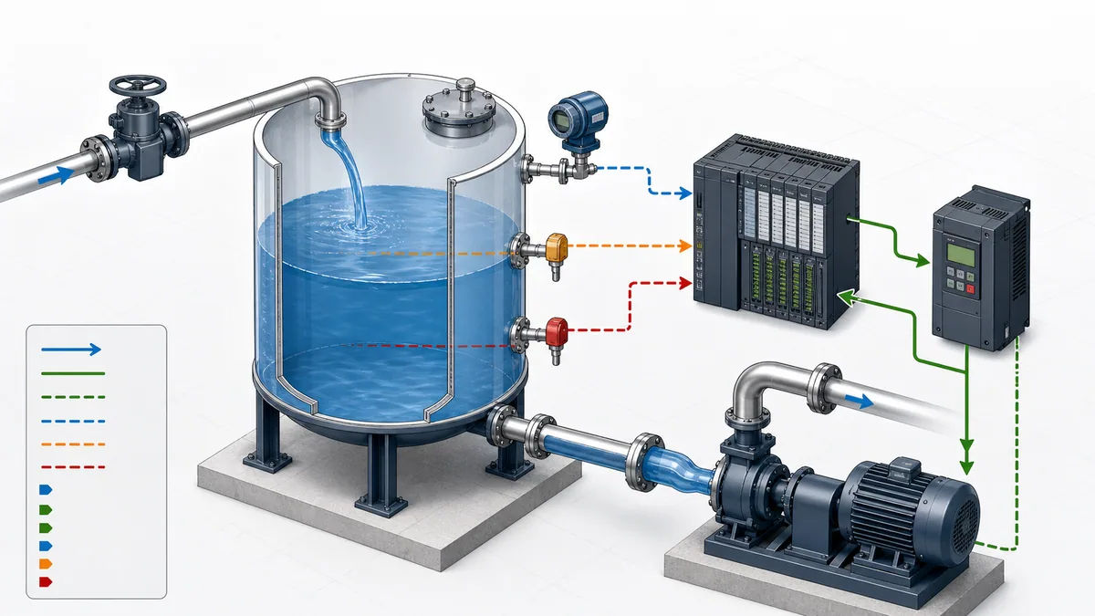
| Stage | Logic responsibility | Failure to expose |
|---|---|---|
| Acquire | Read value, channel status and update age | Frozen/stale value that remains numerically plausible |
| Validate | Check configured raw span, engineering span, channel quality and plausible range | Division by zero, reversed span, overrange/underrange |
| Scale | Convert deliberately with sufficient intermediate width/precision | Integer truncation or overflow |
| Select mode | Arbitrate Off, Manual and Auto with bumpless policy where required | Manual and PID writing the same output |
| Control | Execute supported PID or staged logic at its designed interval | Tuning copied across different task/sample dynamics |
| Limit output | Apply process/equipment limits and rate constraints | Setpoint change creating unsafe or unstable demand |
| Supervise response | Compare command with valve/pump feedback and level trend | Actuator moves but process does not respond, or vice versa |
| Handle bad quality | Hold, substitute, transfer mode or shut down according to requirement | Continuing automatic control on untrusted measurement |
A training formula can explain scaling, but an installed application also needs transmitter range, PLC module representation, live-zero behavior, channel diagnostic definitions, filtering, control direction and fail-state decisions. Use the analog I/O guide and PID tuning guide for those owner intents.
Example 4: PLC-to-robot request and acknowledgement handshake
In a typical cell, the robot controller owns robot motion while the PLC coordinates fixtures, material flow, mode readiness and a cycle handshake. A robust interface uses persistent states that both controllers can observe for longer than one communications update. One-cycle pulses are fragile when controllers and networks run on unrelated schedules.
| Signal concept | Owner | Meaning | Timeout/failure question |
|---|---|---|---|
| Cell request | PLC | A specific operation is requested and remains valid | What cancels a request before acceptance? |
| Robot ready | Robot controller | Correct mode, program and prerequisites are ready for the handshake | Does “ready” include safety state or only robot logic readiness? |
| Request accepted | Robot controller | Request identity/state is captured | How are duplicate/stale requests rejected? |
| Busy | Robot controller | Operation is in progress | How soon must busy appear after acceptance? |
| Complete | Robot controller | Requested operation completed successfully | Must PLC acknowledge before complete clears? |
| Fault/status code | Robot controller | Operation cannot proceed or stopped abnormally | Is the code stable, actionable and versioned? |
| PLC acknowledgement | PLC | Completion/fault result was consumed | What happens if acknowledgement is lost? |
| Heartbeat/quality | Both/interface | Communications evidence is current | Which side owns controlled recovery after a gap? |
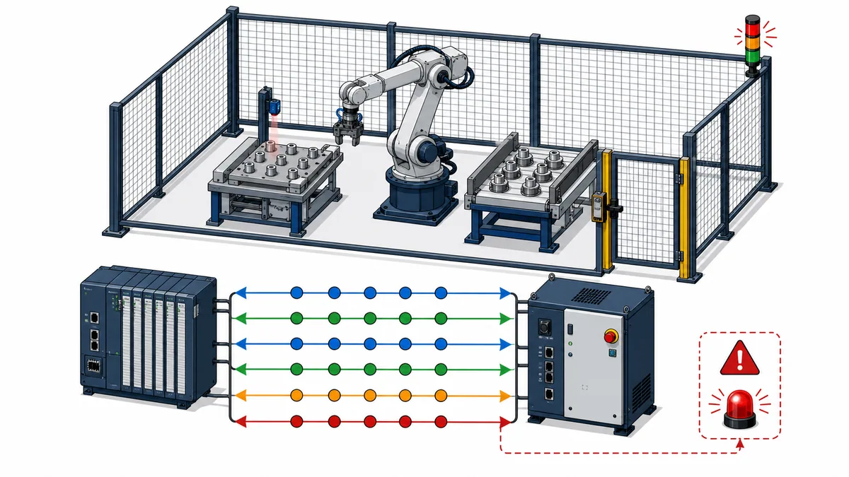
An example sequence is Idle → Requested → Accepted/Busy → Complete → Acknowledged → Idle, with fault and communications-loss transitions from every active stage. Include a request identifier when repeating operations can make a stale complete bit ambiguous. Record both sides of the interface in one synchronized trace.
Safety boundary: an ordinary handshake bit is not a safety function. OSHA's robotics standards overview points users to machinery guarding and hazardous-energy requirements. OSHA's lockout/tagout standard covers servicing and maintenance where unexpected energization, startup or released energy could cause injury. A program example cannot choose the protective measures for a real cell.
Example 5: HVAC air-handler sequence with proof and fault detection
An air-handling unit example should begin with a written sequence of operation and a points list. Occupancy or demand enables a sequence; dampers move to required positions; the supply fan is commanded; airflow or pressure proof must arrive; heating/cooling control is enabled only when prerequisites are met; alarms distinguish failed command, failed proof, sensor quality and limit conditions.
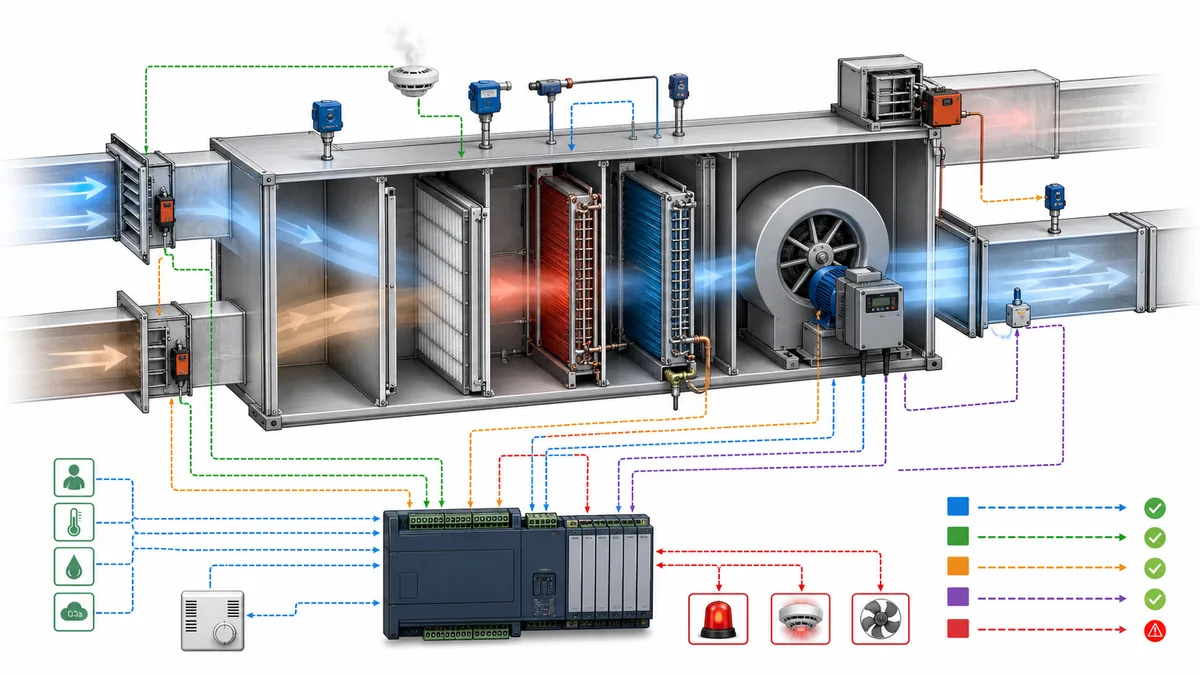
| AHU state | Entry requirement | Main actions | Exit/failure evidence |
|---|---|---|---|
| Off | No demand or approved stop | Outputs at defined off positions; freeze/smoke responses remain according to design | New demand and all start prerequisites |
| Preparing | Demand present | Command outside/return dampers and valves to required start positions | Position proof or preparation timeout |
| Starting fan | Dampers ready | Issue VFD/fan start | Drive/airflow proof or start timeout |
| Running | Fan proven | Enable pressure, temperature and ventilation sequences | Demand removed, proof lost, limit/safety response |
| Stopping | Normal stop | Disable heating/cooling as specified; remove fan; position dampers | Fan proof clears or stop timeout |
| Faulted/degraded | Required proof or value unavailable | Defined equipment response; actionable alarm; controlled reset | Root condition cleared and reset criteria met |
ASHRAE identifies Guideline 36-2024 as guidance for uniform HVAC sequences intended to improve efficiency/performance, control stability and real-time fault detection and diagnostics, with functional tests to confirm implementation. The ASHRAE Handbook controls chapter connects sequences of operation to points lists and commissioning. This example does not reproduce or replace the purchased guideline, the mechanical design or local code requirements.
Example 6: batch mixer with equipment and procedural separation
Batch control becomes more maintainable when physical equipment capability is separated from recipe/procedural intent. A valve module knows how to command and prove a valve. A dosing phase knows how to add an ingredient using that capability. A recipe chooses parameters and phase order. Mixing all three into a single step counter makes reuse, hold/abort behavior and records harder to review.
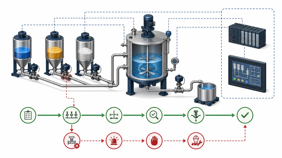
| Procedural phase | Required parameters | Equipment request | Completion evidence | Abnormal cases |
|---|---|---|---|---|
| Prepare | Recipe identifier, vessel target | Confirm route and vessel state | Required equipment available; residual state accepted | Wrong route, vessel not empty/ready, invalid recipe |
| Add ingredient | Target quantity and tolerance | Open selected path/start feeder | Valid measured amount reaches target | No-flow, overshoot, valve fails to open/close, bad scale |
| Mix | Speed and duration | Start agitator at approved demand | Running proof plus elapsed process time | Drive fails, speed deviation, interrupted phase |
| Verify | Quality/process limits | Hold equipment in defined state | Measurements accepted or operator/lab result recorded | Out-of-limit, stale sample, unauthorized decision |
| Discharge | Route and receiving destination | Open discharge/start transfer | Vessel reaches empty/end condition and valve proves closed | Blocked path, incomplete empty, receiving system unavailable |
| Complete | Record requirements | Release equipment according to policy | Batch result and deviations retained | Record gap, pending acknowledgement, held equipment |
The ISA-88 standards page describes Part 1 models and terminology, Part 2 data structures/language guidance, Part 3 recipe models and Part 4 batch production records. It also lists ISA-TR88.00.02-2022 as a machine/unit-state implementation example. Rockwell's application code libraries describe machine-builder libraries for discrete machines and process skids based on ISA-TR88/PackML concepts. Those sources justify the separation pattern; they do not make one vendor implementation portable or compliant by default.
For electronic records subject to FDA requirements, determine applicability with qualified regulatory owners. The current 21 CFR Part 11 text describes scope and controls such as validation, record protection, access, time-stamped audit trails, operational checks and authority checks. A PLC batch sequence by itself does not satisfy those system and procedural controls.
Other PLC applications and the pattern they reuse
| Machine or process | Reused PLC patterns | Evidence unique to the domain | Detailed owner |
|---|---|---|---|
| Filling/capping line | State machine, recipe parameters, reject tracking, machine handshake | Fill quantity, cap/torque evidence, inspection and reject reconciliation | Packaging machine programming |
| Water treatment | Pump/valve objects, sequences, PID, remote I/O, alarm management | Analytical quality, chemical dosing, filter/backwash criteria, remote-site communications | Water treatment PLC guide |
| Traffic exercise | Exclusive phase state, timers, calls and all-red transition | Jurisdictional controller standards, conflict monitoring and field hardware | Traffic-light example |
| Parking gate | Request/authorization, presence loops, position proof, timeout | Entrapment protection, access-system result and vehicle direction | Parking-gate example |
| Motor reversing | Stop-dominant memory and mutual exclusion | Electrical/mechanical interlock, contactor feedback and transition delay | Motor reversing with interlock |
| Servo/indexing station | Motion state, homing, request/complete, fault recovery | Axis limits, dynamics, brakes, following error and safe-motion functions | Motion-control guide |
| Remote compressor/skid | Equipment object, permissives, start proof, communications quality | Process protection, local/remote ownership, stale command and restart policy | Communication troubleshooting |
| Energy or utility auxiliary | Sequence, redundancy, analog control, alarms, historian interface | Sector rules, protection coordination, availability and change control | Industrial systems guide |
The industry label does not determine the controller architecture by itself. The consequence of failure, required response time, equipment package, installed standards, service model, workforce and lifecycle requirements matter more than a generic “PLC versus DCS” rule.
PLC language and architecture choices for the examples
IEC 61131-3:2025 defines the current language suite baseline, but application structure and libraries remain platform-specific.
| Need | Often clear in | Review boundary |
|---|---|---|
| Discrete permissive path | Ladder Diagram | Contact semantics, scan order, duplicate coils/writers |
| Named state machine | Structured Text CASE or SFC elements |
State transition priority, action execution and unknown state |
| Analog signal flow | Function Block Diagram or Structured Text | execution order, status propagation and conversion behavior |
| Reusable motor/valve/pump object | Function block/AOI-equivalent supported by platform | instance state, global data, versioning and call consistency |
| Long machine sequence | SFC elements, phase model or explicit state engine | hold, stop, abort, restart and nested-equipment ownership |
| Repeated channel calculation | Bounded loop/array in Structured Text | declared bounds, worst-case task time and bad-quality handling |
Do not choose a language solely because a short example looks elegant. The result must be diagnosable by the maintenance team, supported by the target controller and reviewable against the acceptance matrix. The Structured Text guide, Ladder tutorial and program organization guide own those deeper decisions.
Troubleshooting any PLC application by evidence boundary
When a system fails, ask where expected evidence stops. Avoid changing logic until the failing boundary is known.
| Boundary | Expected evidence | Typical contradiction | Next controlled check |
|---|---|---|---|
| Request | Correct user/sequence demand with current identity | Operator pressed Start but PLC request is false | HMI/field input and command arbitration trace |
| Permission | Every required ordinary permissive has valid status | Start request exists but one stale permissive blocks | Inspect each source and quality—not a composite bit only |
| Owner/state | One mode/state owns the next action | Manual and Auto both appear active or state cannot transition | Mode/state transition history and writer cross-reference |
| Command | One program location issues the expected output | Internal state is correct but command returns false later | All writers and routine/task order |
| I/O/network | Output/channel and device receive equivalent demand | PLC output image true, field device sees no command | Module status, mapped data and safe physical measurement |
| Actuator | Contactor, drive, valve or damper physically responds | Command present; running/position proof absent | Device diagnostics, energy path and approved isolated test |
| Process | Product, flow, level, pressure or temperature changes | Actuator proves but process variable does not respond | Mechanical/process path and sensor validity |
| Return feedback | PLC receives correct physical result in time | Field action occurred but tag remains false/stale | Sensor, channel, network update and tag mapping |
| Completion | Sequence consumes result once and advances | Complete held/cleared too early; duplicate request appears | Handshake timeline and sequence identifier |
| Recovery | Root condition clears and reset is accepted safely | Reset hides diagnosis or causes automatic restart | Reset criteria, stored state and restart test |
NIST SP 800-82 Rev. 3 treats PLCs, SCADA, building automation and transportation systems as operational technology that interacts with the physical environment, and emphasizes OT performance, reliability and safety requirements. Apply change control, least privilege, backups and approved remote-access controls to the engineering workflow; “troubleshooting” is not authority to bypass safeguards or expose the control network.
Implementation and acceptance checklist
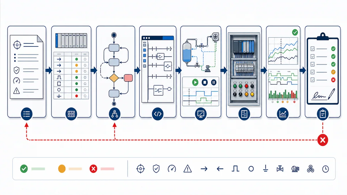
Before code review closes:
- Name the controlled equipment, process objective, interfaces and excluded functions.
- Trace every input/output to a current drawing, channel, data source and engineering meaning.
- Separate request, permissive, command, feedback, state, timeout and diagnostic values.
- Define mode ownership and transitions, including local/remote and maintenance exclusions.
- Set outputs explicitly for idle, starting, running, stopping, faulted and invalid states.
- Derive timeouts from physical expectations and target scheduling, then test their boundaries.
- Define initial, retained and restart behavior for every stateful value and instruction instance.
- Handle bad quality, stale data, communications loss, rejected writes and restored communications.
- Use one writer or explicit arbitration for every physical command.
- Record compiler, controller, firmware, libraries, task period/priority and project version.
- Run normal, simultaneous, held-input, timeout, failure, reset and restart cases.
- Verify the physical energy/actuator/process/feedback chain under an approved test plan.
- Keep safety validation, lockout/tagout, guarding and regulated records in their applicable lifecycles.
Download the PLC application acceptance-matrix template. Replace its example rows with requirements from the real design and retain the signed result with the controlled project record.
Build a complete project from the application patterns
The home PLC two-tank project turns the requirement, I/O contract, state model, code and acceptance approach into one simulation-first portfolio build. Use it after the compact application patterns here when you want a bounded project with retained evidence rather than another list of ideas.
Sources, review scope, and limitations
This pillar was reviewed on 29 August 2026. These direct sources support the cross-application method and its limits; the selected equipment and jurisdiction require their own current source set.
- IEC 61131-3:2025 Edition 4 publication record
- PLCopen coding guidelines for IEC 61131-3
- ISA-88 series of batch-control standards and technical reports
- Rockwell Automation PackML 3.0-based programming quick start
- Rockwell Automation application code libraries
- Rockwell Automation Equipment Phase Monitor documentation
- Siemens S7-1200 pump-control application example
- Siemens programming guideline for S7-1200 and S7-1500
- ASHRAE published standards and guidelines scopes, including Guideline 36-2024
- ASHRAE Handbook Chapter 48: Design and Application of Controls
- US EPA smart sewer technologies and real-time controls
- OSHA 29 CFR 1910.147 control of hazardous energy
- OSHA robotics standards and related requirements
- NIST SP 800-82 Rev. 3 Guide to Operational Technology Security
- eCFR 21 CFR Part 11 electronic records and electronic signatures
- OPC Foundation OPC UA technology overview
Limitations: none of the listings was compiled unchanged on every vendor platform, and the generated figures are conceptual rather than as-built drawings. No generic article can select protective devices, performance levels, process safeguards, hazardous-area methods, environmental permits, building codes or regulated validation controls. Preserve the stated behavior when translating an example, record deviations, and obtain qualified review for the real installation.
Continue Learning
Worked PLC Examples
Reusable Programming Patterns
Frequently Asked Questions
What are the best PLC programming examples for beginners?
Begin with a stop-dominant motor request, then a two-state tank or one conveyor zone. Each exercise should include named I/O, command-versus-feedback, at least one timeout, a fault state, reset criteria and restart testing. Add multi-zone coordination, analog control and external handshakes only after the single-equipment contract is reliable.
What makes a PLC example program realistic?
A realistic example starts from a physical requirement and includes I/O meaning, modes, ownership, persistent state, command, feedback, timing, failure response, diagnostics and acceptance cases. It also states what is excluded—such as safety design, wiring, mechanical sizing, regulated records and target-specific runtime behavior.
Can I copy a PLC example into any controller?
Do not assume that. The algorithm may transfer, but declarations, timers, edge instructions, function blocks, task scheduling, I/O mapping, retentivity and project structure differ. Translate against the selected vendor documentation, compile it, and rerun the same acceptance matrix on the target controller and firmware.
Which PLC application should I use for an interview or practical assessment?
A conveyor transfer or pump-station example is strong because it exposes I/O design, interlocks, state ownership, timers, feedback, diagnostics and testing without requiring a huge project. Explain assumptions, show normal and failed cases, and describe how you would verify the physical system safely.
How do PLCs control conveyors?
A PLC commonly coordinates zone availability, drive readiness, motor commands, running feedback and product sensors. Per-zone states or handshakes prevent one global run bit from hiding ownership. Transfer and start timeouts distinguish a command from confirmed physical movement, while the separately engineered safety system handles hazards.
How does PLC lead-lag pump control work?
The program builds a candidate set from available pumps, applies a defined duty order, stages demand from level or flow, supervises start proof and process response, and substitutes a standby only when policy permits. Rotation must not select an out-of-service, local, faulted or communications-bad unit.
How should a PLC communicate with a robot controller?
Use persistent request, ready, accepted, busy, complete, fault and acknowledgement states that both controllers can observe across asynchronous updates. Add identity or sequence data when repeats could make stale completion ambiguous, supervise every transition, and keep robot/machine safety outside the ordinary handshake.
What should an HVAC PLC sequence include?
Start from the approved sequence of operation and points list. Typical logic distinguishes demand, damper positioning, fan command, airflow or pressure proof, heating/cooling enable, control loops, normal stop, alarms and failed proof. Apply the project’s ASHRAE, mechanical, fire/smoke and local-code requirements.
Can a PLC simulator validate a real application?
It can validate selected logic, state transitions and edge cases before hardware is available. It cannot prove target syntax, task timing, remote-I/O updates, electrical wiring, actuator dynamics, mechanical response, safety performance or regulated validation. Repeat the acceptance cases in an approved target and commissioning environment.
How do I troubleshoot a PLC application that will not run?
Trace where expected evidence stops: request, permissive, mode/state owner, command, I/O or network delivery, actuator response, process change, returned feedback and completion acknowledgement. Use cross-references and a timestamped trace, change one controlled condition at a time, and do not force around an unknown safety or energy boundary.