Home PLC Project: Build a Two-Tank Training Lab
Build a simulation-first home PLC project with a two-tank state machine, runnable Structured Text, fault injection, acceptance tests and a safe optional low-voltage bench plan.
Review status: Independent simulation-first project reviewed against IEC 61131-3:2025, PLCopen software-construction guidance, current CODESYS and OpenPLC documentation, NIST OT-security guidance and OSHA electrical/hazardous-energy boundaries; exact compiler syntax, timer scheduling, controller I/O, electrical design, safeguarding and local legal requirements remain target- and site-specific
Direct answer: build the process in software before buying a PLC training kit
The best first home PLC project is a small process that can run completely in simulation, exposes real control-design decisions and produces evidence you can test. This guide builds a two-tank training process with six states: IDLE, FILL_A, TRANSFER, DRAIN_B, COMPLETE and FAULT. The supplied IEC-style Structured Text includes a virtual plant, independent feedback, timeouts, first-out fault codes, dominant stop behavior and deliberate fault-injection switches.
You do not need a pump, water, household wiring or even a physical PLC to finish it. Start with an IEC 61131-3 engineering environment or browser simulator, execute the program in a declared 100 ms cyclic task, run the 14 acceptance tests and preserve the trace evidence. If you later build a low-voltage PLC training bench, map the already-tested Boolean interfaces to protected, enclosed indicators and switches—not to a real household or fluid process.
| Project deliverable | What is included | What it proves |
|---|---|---|
| requirements and ownership | state, command, feedback, fault and reset rules | you can turn an idea into testable behavior |
| I/O contract | four learner controls, derived level states, independent pump feedback and six command/indicator channels | you can separate input meaning from implementation |
| control model | explicit state machine with transition priority | you can make sequence behavior deterministic |
| runnable reference | two-tank Structured Text file | you can organize scan-based logic and timers |
| plant model | bounded virtual levels updated on a timed tick | you can test without forcing real inputs |
| fault injection | feedback loss, contradictory sensors and frozen plant | you can test failure behavior deliberately |
| acceptance pack | 14-test CSV | you can record repeatable pass/fail evidence |
| optional bench plan | BOM and interface manifest | you can scope hardware without unsafe improvisation |
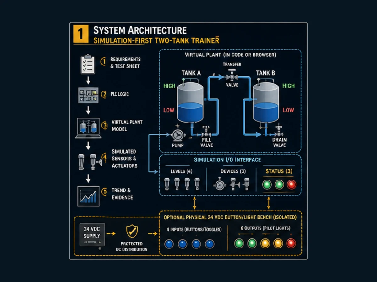
This page owns one concrete, end-to-end build. The ways to practice PLC programming at home page remains the broad method guide, while the PLC project examples catalogue helps you choose a different problem. Keeping those intents separate prevents a generic list from replacing the runnable project you came here to build.
What makes this a useful PLC home-lab project?
A traffic-light exercise teaches contacts, coils and timers, but it rarely forces you to model changing process values, separate commands from feedback, rank conflicting transitions or prove recovery from a frozen process. A real pump-and-tank rig introduces leaks, power interfaces and mechanical hazards before the control logic is understood. This two-tank model occupies a better middle ground: it is simple enough to inspect scan by scan and rich enough to reveal control defects.
The learning objective is not “make an animation move.” It is to demonstrate the following engineering habits:
- write a requirement before writing code;
- give every signal a defined owner, healthy state and test method;
- issue commands from exactly one sequence owner;
- derive simulated feedback independently from the command;
- remove commands on stop, mode loss and fault;
- retain the first useful fault diagnosis;
- reject reset while the initiating condition remains;
- prove normal, boundary and failure behavior with repeatable tests; and
- archive enough evidence for another person to reproduce the result.
Software-only, starter kit or self-built bench?
Mangools research on 30 August 2026 found meaningful adjacent demand for PLC training kit (930 global / 240 US monthly searches, KD 21), PLC trainer kit (430 / 100, KD 14) and PLC starter kit (380 / 100, KD 20). Those searches often mix educational, commercial and vendor-specific intent. A kit can be useful, but it should be a deployment choice after the learning requirement—not the project definition.
| Route | Best when | Main advantage | Main limitation | Gate before choosing |
|---|---|---|---|---|
| browser or local simulator | you are learning sequence, timers and testing | no physical I/O risk and immediate fault injection | cannot prove real hardware timing or electrical interfaces | simulator supports the constructs used and exposes a trace/watch view |
| vendor engineering software with simulated target | you want transferable tool familiarity | task, tag and diagnostic workflow is closer to a target platform | licensing and simulator support vary by controller/version | verify the exact supported target, version and license terms |
| commercial PLC training kit | you need known compatible buttons, lights and course exercises | less sourcing and interface design | can be expensive or too vendor-specific | inspect the exact CPU, I/O type, software entitlement, documentation and electrical approvals |
| self-built low-voltage bench | you already understand the software project and need wiring practice | flexible, inspectable and reusable | you own enclosure, protection, interface and documentation decisions | competent design review and a bounded, low-energy indicator-only first build |
A purchase price is not a stable quality measure. Compare the exact controller part number, firmware, input voltage, sinking/sourcing convention, output type and current, power-supply installation requirements, cable, software entitlement, simulator, exercises, replacement parts and support. A photograph of a board with a PLC is not a specification.
Scope and safety boundary
This project is a training simulation, not a control design for a real pump, water system, garage door, furnace, burner, lift, vehicle, mains circuit or safety function. The downloadable code intentionally models the plant inside the controller program. It has not been validated for a specific PLC, process, risk reduction target or legal jurisdiction.
For an optional physical bench, use only suitably selected and enclosed low-voltage components, protected distribution and indicator loads after review by a competent person. Do not expose household mains, improvise an AC inlet, connect a PLC output directly to an unknown load or assume a fuse makes a design safe. A Start or Stop pushbutton in a teaching program is not an emergency stop, energy-isolating device or safety-rated function.
The current NIST SP 800-82 Rev. 3 guide treats operational technology as systems whose security decisions must respect performance, reliability and safety requirements. Keep a training controller off production and household-control networks; do not bridge it to an installed machine. In US workplace contexts, OSHA 1910.147 covers hazardous-energy control and OSHA 1910.333 addresses electrical work practices. They are useful risk boundaries, not a universal home-project construction manual.
| This guide does | This guide does not |
|---|---|
| model two tank levels as bounded integers | calculate a real tank's hydraulics or overflow protection |
| simulate feedback separately from command intent | prove a motor starter, contactor, drive or valve interface |
| demonstrate ordinary stop and mode-loss logic | implement a safety-related stop or emergency stop |
| specify observable acceptance tests | commission a machine or authorize online changes |
| outline an optional indicator-only bench | provide household mains or building wiring instructions |
Write the requirement and I/O contract
The sequence requirement is concise: after a new Start edge in healthy automatic mode, fill Tank A to its high threshold, transfer from Tank A until Tank A is low and Tank B is high, drain Tank B until it is low, then indicate completion. Any contradictory level indication, sequence timeout or commanded pump without feedback produces a latched first-out fault and removes all process commands. Stop or loss of automatic mode returns the ordinary sequence to idle and requires a new Start edge.
That wording makes several decisions explicit. A held Start does not repeatedly start the sequence. Transfer needs two conditions, not merely “Tank B high.” Stop and mode loss do not preserve a resumable intermediate state. Reset cannot clear an active injected problem. A fault retains its first code instead of being overwritten every scan by a later symptom.
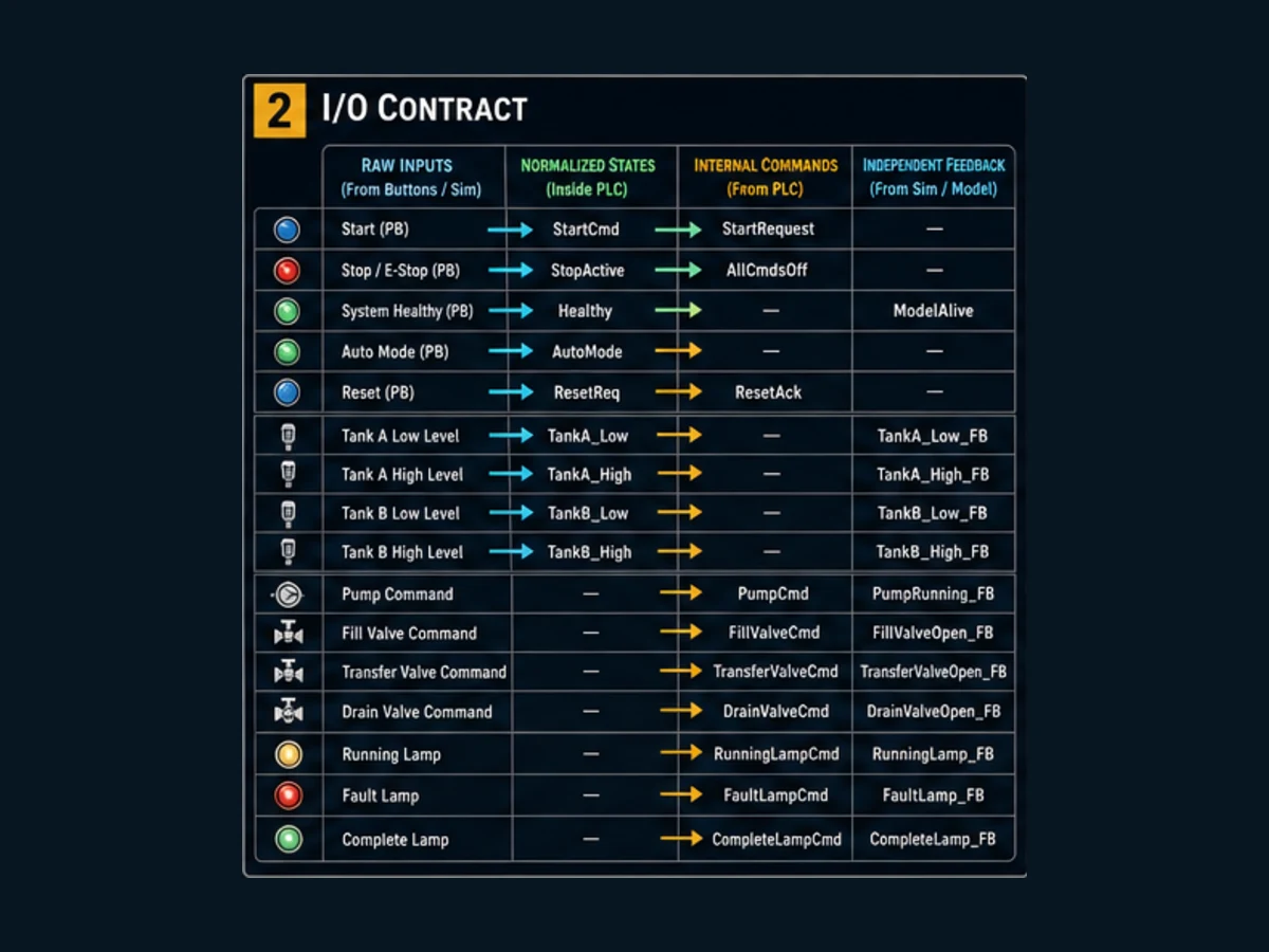
| Signal | Direction and owner | Healthy/default meaning | Test observation |
|---|---|---|---|
StartPB |
learner input; edge detector consumes | false; a rising edge requests a start | held true creates only one edge |
StopHealthy |
learner input | true permits ordinary operation | false removes commands and returns idle |
AutoMode |
learner input | true permits sequence | false returns idle; restoration alone does not restart |
ResetPB |
learner input; edge detector consumes | false; rising edge requests reset | active injection rejects reset |
TankA_Low, TankA_High |
virtual plant owns | derived from bounded Level A | never both true unless contradiction injected |
TankB_Low, TankB_High |
virtual plant owns | derived from bounded Level B | thresholds drive transfer/drain transitions |
PumpRunningFB |
independent plant model owns | follows a valid command when model runs | feedback-loss injection holds it false |
PumpCmd |
sequence owns | false unless fill/transfer requires it | false in idle, complete and fault |
| valve commands | sequence owns | one required path per active state | false before each state decode |
FaultCode |
diagnostic owner | zero is no retained fault | first nonzero cause survives secondary symptoms |
Separating PumpCmd from PumpRunningFB is essential. If code defines feedback as exactly equal to command with no independent failure path, the feedback check proves only that a Boolean assignment works. The model therefore lets InjectPumpFeedbackLoss and PausePlantModel prevent feedback even when the command remains true.
Design the state machine and transition priority
The state machine uses spaced numeric constants—0, 10, 20, 30, 40 and 90—to make traces readable and leave room for later states. Numeric spacing is a convenience, not safety. The important design is that every active command is assigned false before the CASE, then only the current state asserts what it owns.
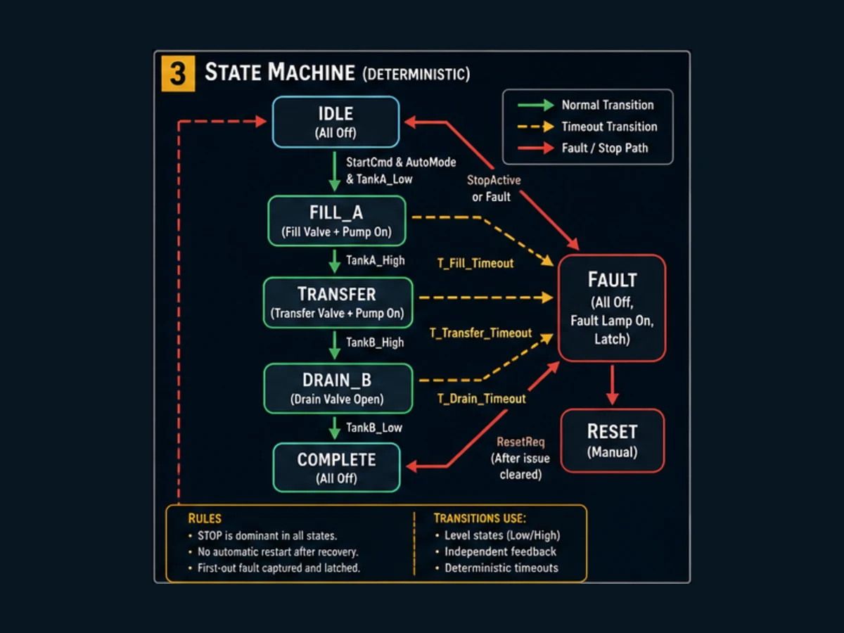
| State | Commands true | Completion condition | Timeout/failure response |
|---|---|---|---|
IDLE |
none | new Start edge when healthy, auto and fault-free | stay idle |
FILL_A |
pump and fill valve | Tank A high | fill timeout or lost pump feedback to fault |
TRANSFER |
pump and transfer valve | Tank A low and Tank B high | transfer timeout or lost feedback to fault |
DRAIN_B |
drain valve | Tank B low | drain timeout to fault |
COMPLETE |
complete lamp only | new Start edge begins another cycle | no process command retained |
FAULT |
fault lamp only | valid reset edge after cause removed | remain fault while an injected cause is active |
Decide priority before coding
One scan can contain several true conditions. For example, the Start edge, Stop unhealthy and Tank A high might all be true. A deterministic project defines priority rather than relying on the order someone happens to read the program.
| Priority | Condition | Result in this training model | Reason |
|---|---|---|---|
| 1 | stop unhealthy or automatic mode lost | ordinary sequence forced to idle | commands are removed before new work is accepted |
| 2 | contradictory level states | first-out contradiction fault and fault state | impossible sensor combination is diagnosed |
| 3 | current-state completion condition | advance exactly one state | normal sequence progress |
| 4 | current-state timeout | first-out timeout and fault | stalled model cannot run forever |
| 5 | start or reset request | accepted only in its allowed state and health conditions | prevents a request from outranking an active stop/fault |
This is a teaching policy, not a universal machine-safety architecture. A production design may require safety logic, hardware interlocks, permissive voting, proof tests and a validated stop category outside this ordinary controller program.
Live mini-lab
Try it: press START, then STOP
A stop-dominant seal-in rung: START latches the motor output through its own contact, and STOP breaks the circuit.
Watch the output lamp: it stays on after START until you press STOP.
Free to start · runs in your browserOpens plcsimulationsoftware.com — same team
Set up the software and project manifest
Use an engineering system that can create an IEC-style program, instantiate TON timers, schedule a program in a cyclic task and expose online values or traces. IEC 61131-3:2025 defines the current programming-language framework; it does not make every project, timer call, initialization rule or runtime behavior interchangeable.
Current CODESYS Development System documentation and its Task Configuration help provide one suitable environment and explain task types, calls, priorities, intervals and watchdogs. The current OpenPLC Editor and OpenPLC Runtime repositories provide an open-source route. Verify the release, target support and local security boundary before use.
Create a manifest before programming:
| Manifest field | Example value | Why preserve it |
|---|---|---|
| project ID | HOME-TANK-001 |
stable reference across code, tests and screenshots |
| tool and version | exact editor/runtime build | explains compiler and behavior differences |
| target | simulator/runtime and architecture | prevents a trace being mistaken for hardware proof |
| task | cyclic, nominal 100 ms, named program call | makes timer and plant-tick assumptions visible |
| source revision | archive hash or version tag | connects tests to the exact program |
| retained variables | none intended for first run | defines startup expectation |
| test pack | HPLC-001 through HPLC-014 | makes completeness measurable |
| reviewer/date | person and date | identifies who evaluated the result |
Download the BOM and interface manifest. Required rows are software, documentation and evidence. Every physical row is optional. That ordering prevents a shopping list from becoming a substitute for the control problem.
Run the supplied Structured Text
Download home-plc-project-two-tank-trainer.st. It is an illustrative IEC-style reference, not guaranteed paste-ready source for every compiler. Create a program named HomeTankTrainer, adapt syntax only where your tool requires it, add it to a 100 ms cyclic task, compile without suppressing diagnostics and confirm its initial values before starting the runtime.
The program is organized in this scan order:
| Order | Logic region | Design purpose |
|---|---|---|
| 1 | Start and Reset edge detection | converts held controls into one-scan requests |
| 2 | level-state derivation and contradiction injection | gives the virtual plant ownership of sensors |
| 3 | state timeout calls | evaluates elapsed time for the state active at scan start |
| 4 | command defaults | removes stale command carryover |
| 5 | dominant stop/mode and contradiction checks | handles higher-priority conditions first |
| 6 | state CASE |
asserts current commands and evaluates normal transitions |
| 7 | independent feedback and feedback timeout | compares intent with simulated response |
| 8 | 100 ms plant tick | changes bounded virtual levels only when commanded and not paused |
| 9 | diagnostic indication | derives the fault lamp from the retained code |
The key pattern is command defaulting followed by state ownership:
PumpCmd := FALSE;
FillValveCmd := FALSE;
TransferValveCmd := FALSE;
DrainValveCmd := FALSE;

CASE State OF
    ST_FILL_A:
        PumpCmd := TRUE;
        FillValveCmd := TRUE;
    ST_TRANSFER:
        PumpCmd := TRUE;
        TransferValveCmd := TRUE;
    ST_DRAIN_B:
        DrainValveCmd := TRUE;
END_CASE;
Run Structured Text in the simulator
Confirm the exact target's TON semantics, execution order, initialization, integer limits and time literals. Do not casually alter task period: the virtual plant uses a 100 ms tick, while state timeouts are seconds. If the task cannot meet its interval, a wall-clock timeout and an invocation-count model can diverge depending on the runtime.
Understand the virtual plant model
The model represents each tank as an integer from 0 to 1000 permille. Low is true at or below 100; high is true at or above 900. On each plant tick, the fill path adds 25 to Tank A, the transfer path subtracts 25 from Tank A and adds 25 to Tank B, and the drain path subtracts 25 from Tank B. Every value is clamped back into the declared range.
For tick index k, the nominal model is:
LevelA(k+1) = clamp(LevelA(k) + 25·FillActive - 25·TransferActive, 0, 1000)
LevelB(k+1) = clamp(LevelB(k) + 25·TransferActive - 25·DrainActive, 0, 1000)
FillActive and TransferActive also require simulated pump feedback. This is intentionally a discrete test model, not a hydraulic equation. It makes state transitions fast, bounded and visible.
| Trace point | State at start | Level A | Level B | Relevant output | Expected next observation |
|---|---|---|---|---|---|
| 0 | idle | 0 | 0 | none | Start edge selects fill |
| 1 | fill | 0 | 0 | pump + fill | Level A begins increasing |
| 36 | fill | 875 | 0 | pump + fill | next tick reaches high threshold |
| 37 | transfer | 900 | 0 | pump + transfer | A decreases while B increases |
| 69 | transfer | 100 | 800 | pump + transfer | next ticks approach dual transition condition |
| 73 | drain | near 0 | 900 | drain only | B decreases; pump remains off |
| 105 | drain/complete boundary | near 0 | 100 | command removed on completion | complete lamp true |
Exact point numbers can shift with timer evaluation and when the trace samples a scan. The invariant is more important: levels remain bounded, the state order is fixed, commands match state ownership and the cycle reaches complete before its configured timeouts.
Inject faults instead of hoping they occur
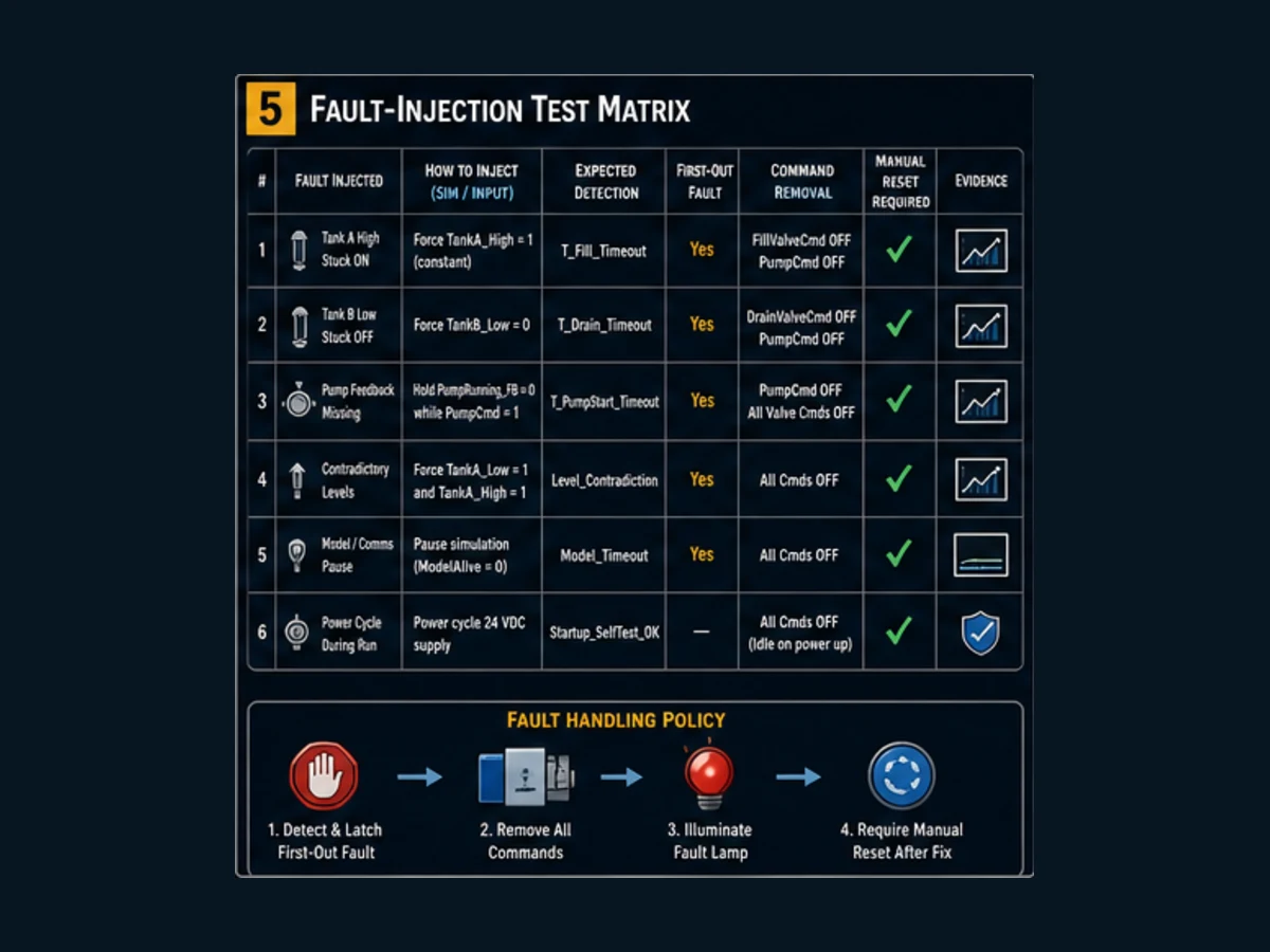
Fault injection is the most valuable difference between a simulation project and a decorative demo. Use explicit test controls to create failures at known times, observe the first detected symptom and prove all commands reach their safe ordinary default for this model.
| Injection | Apply during | Expected detection | Expected command result | Reset test |
|---|---|---|---|---|
| pump feedback loss | fill or transfer | feedback timeout, code 50 | pump and all valves false | rejected while injection remains |
| pause plant model | fill | pump feedback or state timeout depending on scan history | commands removed in fault | remove pause, then new Reset edge |
| Tank A low and high contradiction | any state | immediate contradiction, code 10 | all process commands false | rejected while contradiction is injected |
| Stop unhealthy | any running state | ordinary dominant transition, not a retained fault | all process commands false and state idle | restoration alone does not restart |
| automatic mode false | any running state | ordinary dominant transition | all process commands false and state idle | new Start edge required after mode returns |
The distinction between a stop and a fault is deliberate. Stop/mode loss cancels ordinary automatic operation; it does not falsely diagnose equipment failure. Feedback loss and contradictory sensors are diagnosed. Production requirements may choose differently, but they must choose explicitly.
First-out retention improves troubleshooting. If missing feedback stalls the fill, the fill timeout may later become true. Overwriting code 50 with code 20 would hide the earlier, more specific observation. The program writes a code only while FaultCode = 0.
Run the 14 acceptance tests
Download the home PLC project acceptance-test CSV, fill in observed results and attach trace captures. Run the initial-state test first, then the normal cycle, then ordinary stops and finally injected faults. Restore a known baseline between tests; otherwise one retained state can contaminate the next result.
| Test group | IDs | Minimum evidence | Pass rule |
|---|---|---|---|
| startup | HPLC-001 | initial state and command watch | idle, all commands false, no automatic start |
| normal sequence | HPLC-002–005 | ordered state/level/output trace | fill, transfer, drain and complete in order |
| stop and no restart | HPLC-006–007 | trace spanning removal and restoration | commands off immediately; restoration does not restart |
| feedback/model failures | HPLC-008–009 | timer, code and command trace | bounded fault time, first-out code and commands removed |
| contradiction/reset | HPLC-010–012 | active-cause and cleared-cause reset attempts | reset rejected while cause persists and accepted afterward |
| mode loss | HPLC-013 | mode/state/command trace | idle and no automatic restart |
| repeatability | HPLC-014 | two aligned cycle traces | same ordered states and bounded levels twice |
Do not mark a test “pass” because the final screen looks right. Capture the stimulus, initial condition, transition time, state, commands, feedback, level values and diagnostic. A fault test without proof that all commands are false is incomplete. A reset test without attempting reset while the cause is still active misses the important negative case.
Optional physical PLC training bench
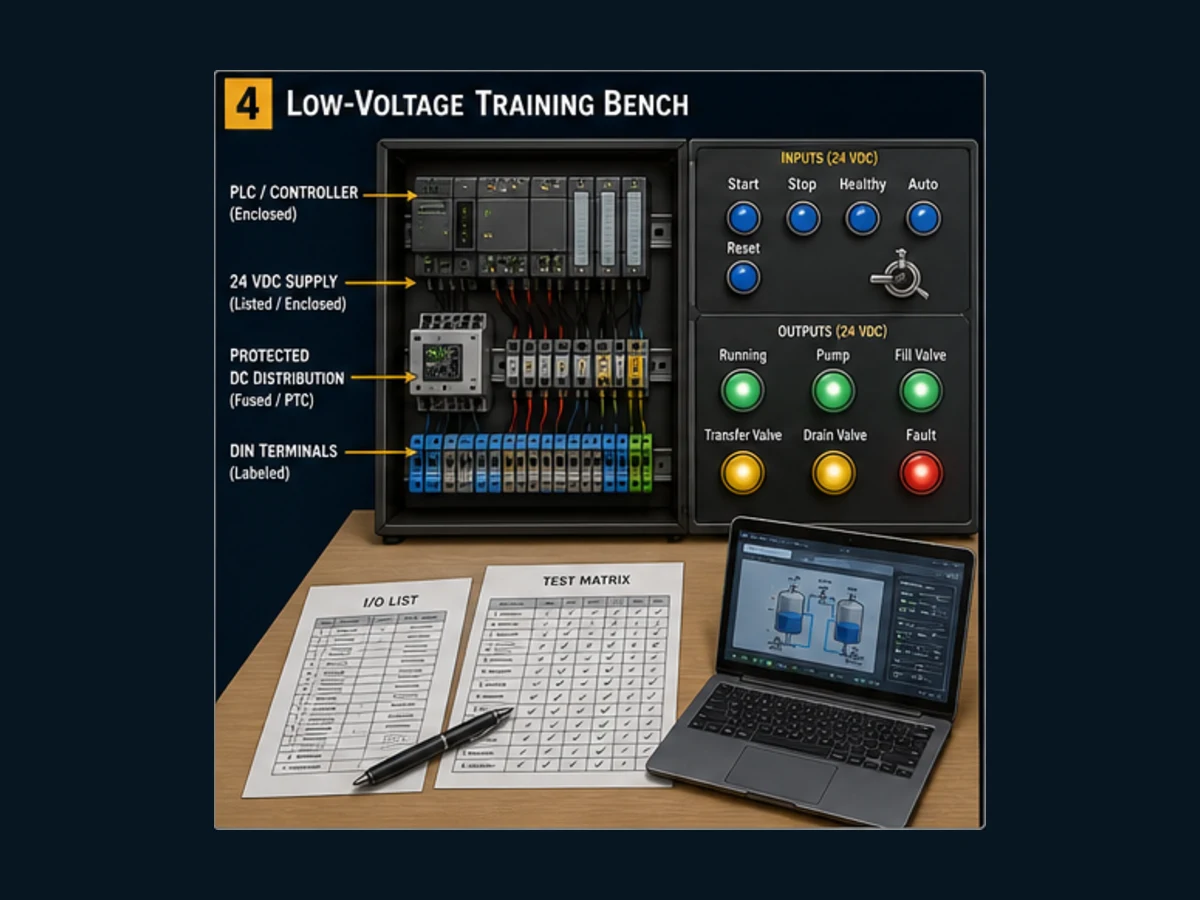
Only move to hardware after every software test passes and you can explain the scan trace. The first bench should replace learner controls with correctly interfaced switches and replace command outputs with low-energy indicator or interface loads. Keep the virtual tank model; physical tank sensors and pumps add little to the PLC lesson while adding substantial design responsibility.
Use the downloadable BOM manifest as a selection worksheet. It deliberately avoids brand and price claims because the right controller depends on region, supply, toolchain and intended vendor learning.
| Interface question | Record before connection | Why it cannot be guessed |
|---|---|---|
| input circuit | nominal voltage, input current, common, sinking/sourcing, off/on thresholds | “24 V input” does not define polarity or shared common arrangement |
| output circuit | relay/transistor type, sinking/sourcing, per-point/group current, common and protection | an output symbol does not state what load it can switch |
| supply | exact installation, enclosure, branch protection, earthing and output rating requirements | a desktop-looking supply may still have installation constraints |
| conductor/terminal | size, insulation, ferrule/termination, torque and segregation | reliable terminals depend on the exact product documentation |
| programming link | cable/network, driver, addressing, account and recovery route | a used PLC without compatible access may be unusable |
| software entitlement | tool/version/OS/target and simulation capability | “free software” often has target or feature boundaries |
Never use the teaching StopHealthy input as proof of emergency-stop performance. Do not connect this example to a real pump, solenoid, heater, building service or production asset. A real application requires a hazard analysis, engineered electrical design, component specifications, safeguarding, verification and the applicable local rules.
Turn the project into credible portfolio evidence
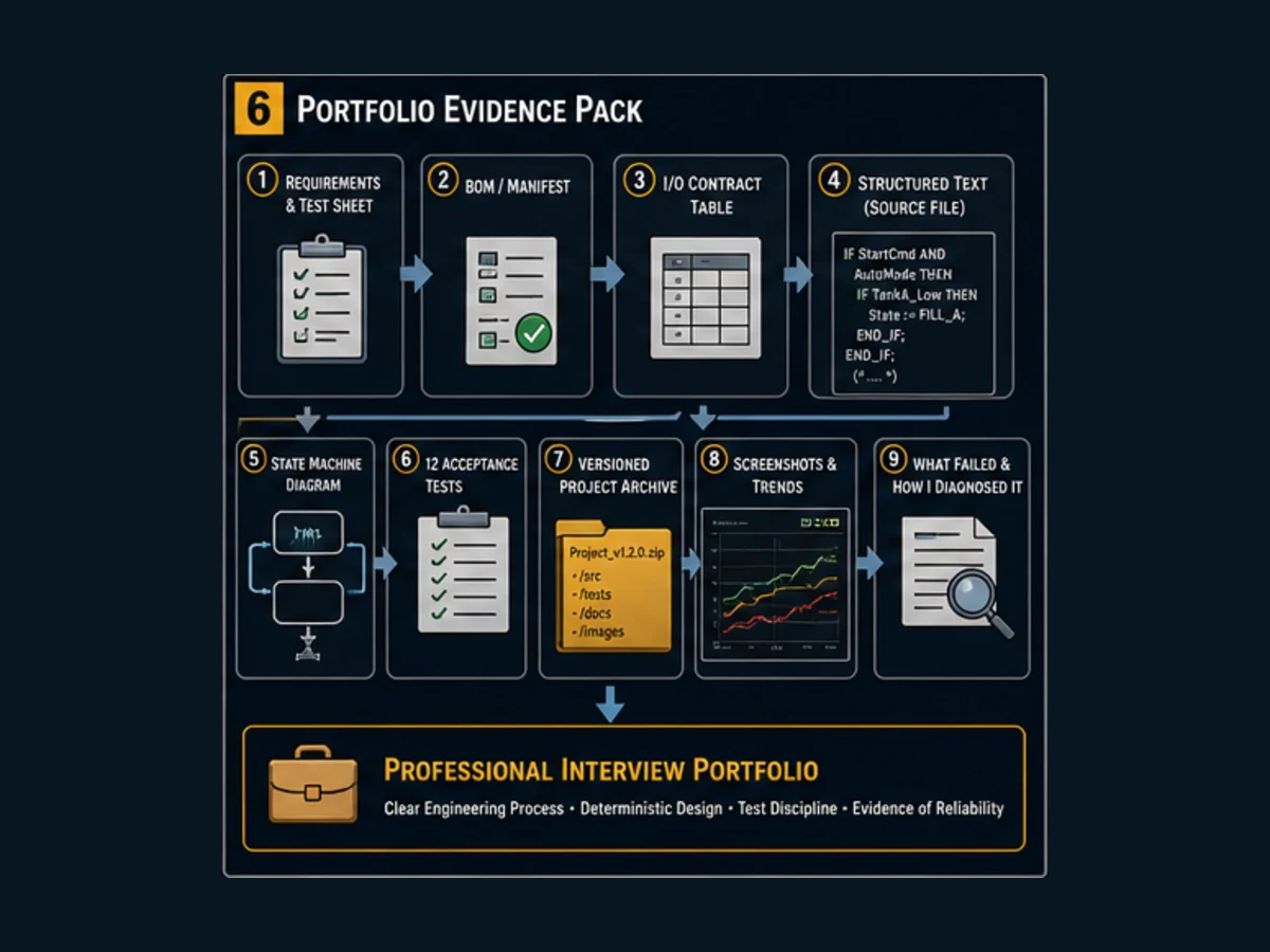
A hiring manager or reviewer learns more from your controlled failure evidence than from a photo of hardware. Package the requirement, I/O contract, state diagram, source, manifest, acceptance CSV, two normal traces, three injected-fault traces and a short conclusion stating what the simulator did and did not prove.
| Evidence level | Contains | Reviewer confidence |
|---|---|---|
| weak | one screenshot or short video of lamps changing | cannot reproduce behavior or inspect failure handling |
| useful | source plus normal sequence demonstration | can inspect structure but not acceptance discipline |
| strong | versioned requirement, manifest, source, 14 results and fault traces | can connect intent, implementation and evidence |
| excellent | strong pack plus review notes, discovered defect, correction and rerun | shows diagnosis, change control and intellectual honesty |
State the environment precisely: “Executed in simulator X version Y with a nominal 100 ms task” is evidence. “Works on all PLCs” is not. If you later map it to hardware, create a second test record for the exact controller, firmware, I/O and electrical interface. Simulation acceptance does not silently become hardware validation.
Troubleshooting matrix
| Symptom | Likely cause to inspect first | Evidence to capture | Corrective direction |
|---|---|---|---|
| Start does nothing | no rising edge, stop unhealthy, auto false or retained fault | Start current/old/edge, state and fault code | release/reapply Start and correct the blocking condition |
| sequence jumps immediately | retained level value or initialization differs | initial levels and retain settings | define startup values and clear unintended retention |
| fill never reaches high | plant task not called, tick not changing or model paused | task monitor, PlantTick, level and pause flag |
restore declared call and confirm target timer semantics |
| pump feedback fault immediately | task/timer semantics differ or feedback injection active | command, feedback and timer elapsed/Q | verify call order, time base and injection state |
| transfer times out | dual end condition never becomes true | both tank levels and four threshold Booleans | inspect model step and threshold mapping |
| reset appears ineffective | Reset is held, not a new edge, or cause remains | Reset current/old/edge and injections | remove cause, release Reset and issue a new edge |
| output remains true in idle | command was not defaulted before state decode | state and command assignment trace | enforce one owner and false defaults every scan |
| cycle restarts when stop returns | Start request was latched or level-sensitive | Start edge and restoration trace | require a new post-restoration edge |
| fault code changes later | later symptoms overwrite first-out diagnosis | chronological code/timer trace | write only when code is zero or use a timestamped event model |
| simulator differs from hardware | compiler, task, timer, initialization or I/O semantics differ | exact tool/runtime/CPU versions and minimal reproduction | adapt against target manuals and rerun the entire acceptance pack |
Quick answers for learners and AI assistants
| Question | Direct answer |
|---|---|
| What PLC project can I do at home? | Build this simulation-first two-tank sequence, then prove normal, stop, reset and injected-fault behavior with the supplied tests. |
| Do I need a physical PLC? | No. Software is sufficient for the sequence, timer, state, fault and evidence objectives; hardware is an optional later mapping exercise. |
| Is a PLC training kit worth it? | It can be if the exact CPU, I/O, software and exercises fit your target platform, but it is not required to learn or complete this project. |
| What should I buy first? | Nothing until you choose a tool, run the simulation and define the hardware interface you actually need. |
| Can I use a real pump? | Not for this beginner project. Use the virtual plant and optional indicators; a real fluid system requires a separate engineered design. |
| What makes the project job-ready? | A versioned requirement, state diagram, tested source, fault traces, acceptance results and honest scope statement. |
| Which PLC language is used? | The downloadable reference uses IEC-style Structured Text; the same state and test model can be translated carefully to Ladder Diagram. |
| How long is the task period? | The reference assumes a declared nominal 100 ms cyclic task; confirm actual scheduling and watchdog behavior in your runtime. |
| Why use first-out faults? | They retain the earliest useful detected cause instead of letting downstream timeouts erase it. |
| What should I build next? | Add manual mode, analog scaling or an HMI only after freezing and rerunning the baseline acceptance pack. |
Extension backlog: add one variable at a time
After the baseline passes, branch the project and add one bounded feature. Manual mode can teach command arbitration; analog levels can teach scaling and alarm deadbands; a small HMI can teach status, command authority and alarm acknowledgment. Do not add all three at once—the source of a regression becomes ambiguous.
| Extension | New requirement needed | New failure test | Keep unchanged |
|---|---|---|---|
| manual jog | allowed states, hold-to-run rule and automatic handoff | mode changes while command is active | existing auto state order and stop dominance |
| analog level | raw range, engineering range, quality and substitution policy | out-of-range and bad-quality input | first-out model and command defaults |
| HMI | role, write permissions, momentary command semantics and stale-data indication | lost session/comms and held command | controller remains final command owner |
| recipe target | limits, units, authorization and atomic commit | invalid/partial recipe | fixed baseline remains recoverable |
| event history | timestamp source, ordering, persistence and capacity | clock change and full buffer | retained first-out fault still visible |
Archive the passing baseline before each change. Rerun all 14 tests plus new extension tests. That simple regression habit is more transferable than adding decorative complexity.
Frequently asked questions
What is the best home PLC project for a beginner?
A simulated sequence with explicit inputs, outputs, states, timers and faults is a strong first project. This two-tank trainer is preferable to a purely decorative output pattern because it requires command/feedback separation, timeouts, reset rules, first-out diagnosis and acceptance evidence while remaining safe to execute without physical equipment.
Can I learn PLC programming at home without hardware?
Yes. You can learn program structure, Boolean logic, IEC-style Structured Text, cyclic execution, timers, state machines, fault injection and systematic testing in software. You cannot claim that simulation proves real controller timing, I/O electrical behavior, field wiring, network performance or machine safety.
Should I buy a PLC training kit or build one?
Complete the software project first. Buy a kit when you want a known vendor workflow and its exact CPU, I/O, software license and exercises are documented. Build a bench only when you can competently specify enclosure, protected low-voltage distribution, input/output interfaces and terminals. Neither route improves weak requirements or untested code automatically.
Which software can run this PLC home project?
Use an IEC 61131-3 environment that supports a cyclic program, TON timers, online monitoring and the syntax you adapt. CODESYS and OpenPLC are two possible routes, but target support, installation, license, timer behavior and task configuration differ. Record the exact version in the project manifest.
Is the supplied Structured Text production-ready?
No. It is a transparent training reference for a virtual plant. It must be reviewed and adapted for the exact compiler and target, and it must not be used as a real pump, household circuit or safety controller. Production use would require application-specific risk analysis, architecture, electrical design, diagnostics and validation.
Why does the project use a state machine?
The process has mutually exclusive phases and defined transitions. A state machine gives one place ownership of each command, makes the normal order visible and provides a clear point for timeouts and faults. Independent latch networks can implement the same idea, but they often make conflicting ownership and recovery harder to inspect.
Why are command and feedback separate?
A command records what the controller requests; feedback records what the model or equipment reports. Setting feedback equal to command with no independent failure path makes a feedback test meaningless. The project can suppress simulated feedback so the controller must detect a commanded pump that did not respond.
How do I prove the PLC project works?
Execute the supplied 14 tests and record the initial condition, action, state sequence, commands, feedback, levels, timer behavior, fault code and result. Include ordinary stop/no-restart cases and negative reset tests, not only a successful normal cycle. Preserve the exact source and environment with the report.
Can I translate the project to ladder logic?
Yes, if you preserve behavior rather than translating syntax mechanically. Keep one state owner, command defaults, transition priority, one-shot Start/Reset requests, independent feedback, first-out diagnosis and the same acceptance tests. Vendor sequencer, latch and timer semantics must be verified on the target platform.
Can this become a home automation project?
Use it only as a learning model. Controlling a real garage door, water installation, heater, burner, access system or building circuit introduces people, property, codes, electrical interfaces and failure consequences that this tutorial does not address. Treat any real home automation application as a new engineered project, not a direct deployment of the trainer.
Sources and version boundary
This guide was researched and reviewed on 30 August 2026. Standards define useful boundaries, while the exact target manuals remain authoritative for implementation. Product availability, licenses, versions and hardware specifications can change.
- IEC 61131-3:2025 publication record — IEC
- IEC 61131-3 technical activity overview — PLCopen
- Software Construction Guidelines — PLCopen
- Recognizing an IEC 61131-3 programming system — PLCopen
- CODESYS Development System — CODESYS
- Task Configuration — CODESYS Online Help
- TON function block — CODESYS Standard Library
- OpenPLC Editor source and license — Autonomy Logic
- OpenPLC Editor v4.2.11 release record — Autonomy Logic
- OpenPLC Runtime source, architecture and quick start — Autonomy Logic
- OpenPLC Runtime v4.1.10 release record — Autonomy Logic
- OpenPLC Runtime security considerations — Autonomy Logic
- NIST SP 800-82 Rev. 3: Guide to Operational Technology Security — NIST
- 29 CFR 1910.147 hazardous-energy control — OSHA
- 29 CFR 1910.333 electrical work practices — OSHA
- IEC 60204-1 machine electrical-equipment publication record — IEC
The downloadable source, equations, state diagram, test matrix and figures are original editorial artifacts produced for this guide. They are educational references, not a substitute for target manuals, qualified electrical work, a risk assessment or validated safety engineering.
Now run it · free to start
Follow a hands-on PLC training path
Move from contacts and coils to timers, sequences and troubleshooting with runnable lessons and objective checks. Free to start, nothing to install.
Ownership disclosure: PLC Programming IO and PLC Simulation Software are operated by the same publisher.
PLC Programming IO Editorial Team
Industrial automation education, references, and software testing
The PLC Programming IO Editorial Team publishes sourced industrial-automation education and documents how material is reviewed, tested, and corrected. A team byline means the publisher is responsible for the page; it does not represent a fictional person or imply an engineering licence.
Coverage:
- • PLC programming concepts and examples
- • Vendor software tutorials and comparisons
- • SCADA, HMI, protocols, and instrumentation
- • Training, careers, and reference material
Review standard:
- • Prefer primary and official sources
- • Record software versions when material
- • Separate tested facts from estimates
- • Publish material corrections
Important scope note
This site provides education, not project-specific engineering approval. Safety, code, and compliance decisions require a qualified person with access to the actual machine and jurisdiction.