Conveyor Belt PLC Programming: Logic, VFDs and Safety
Build conveyor PLC logic with stop-dominant motor control, VFD handshakes, product tracking, zone accumulation, fault recovery and a practical test matrix.
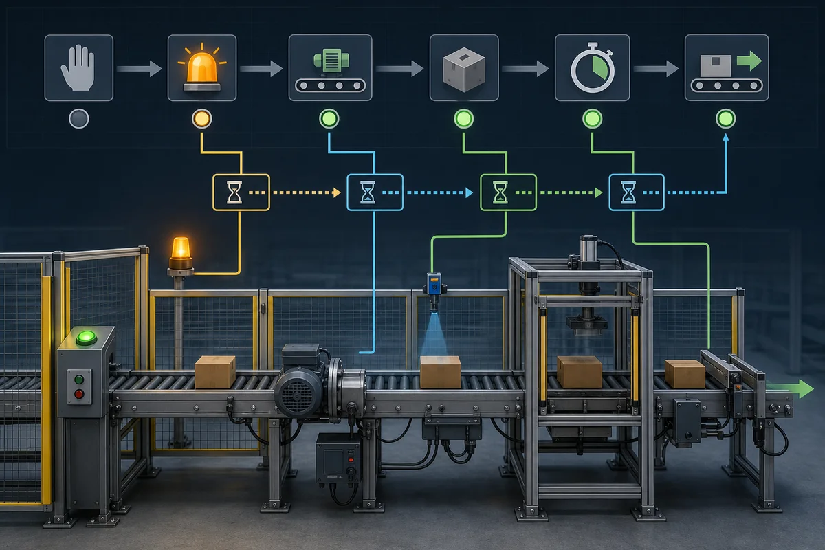
A reliable conveyor PLC program separates five concerns: safety, operating mode, motor/VFD command, product tracking and fault recovery. The standard PLC may request motion only when its permissives are true; a separately designed safety function removes or controls hazardous motion. Start downstream before upstream, stop upstream before downstream, and verify every transition with feedback and timeouts.
The ladder or Structured Text is rarely the hardest part. The real engineering work is defining what “ready,” “running,” “blocked,” “safe” and “recovered” mean for the actual conveyor.
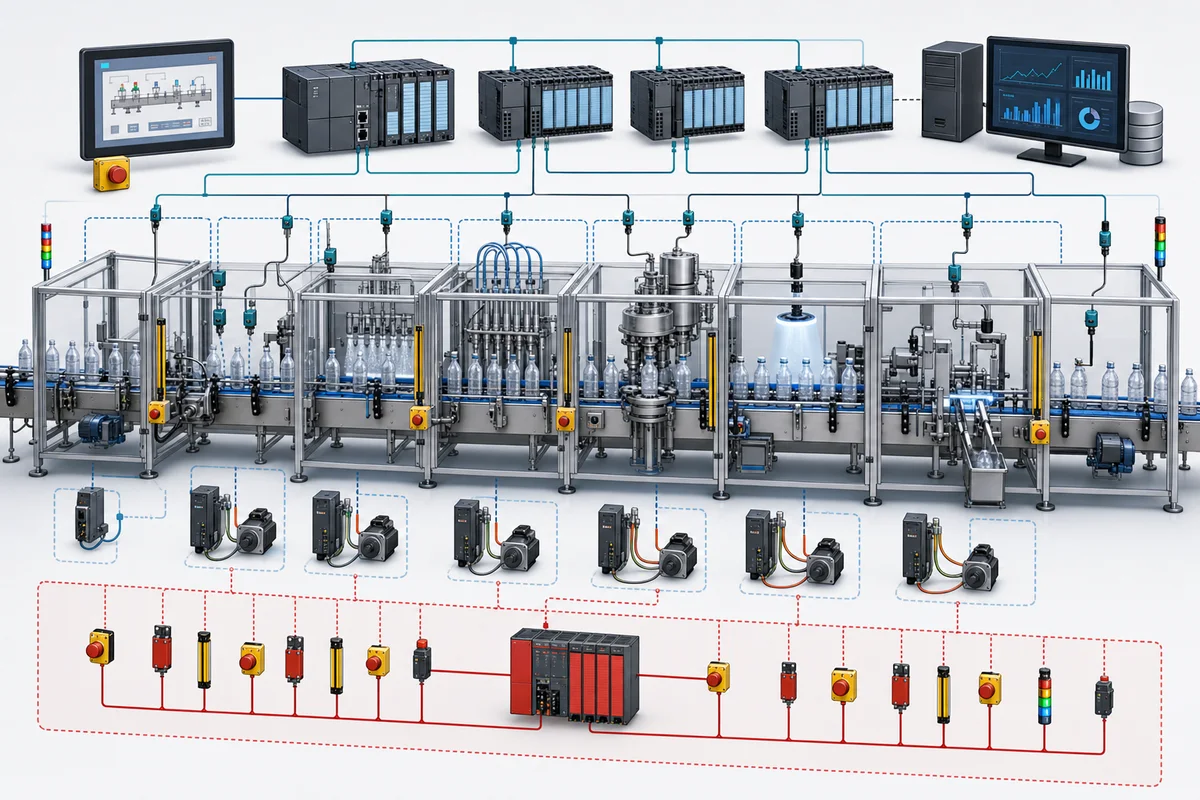
Reference architecture
| Layer | Typical components | PLC responsibility |
|---|---|---|
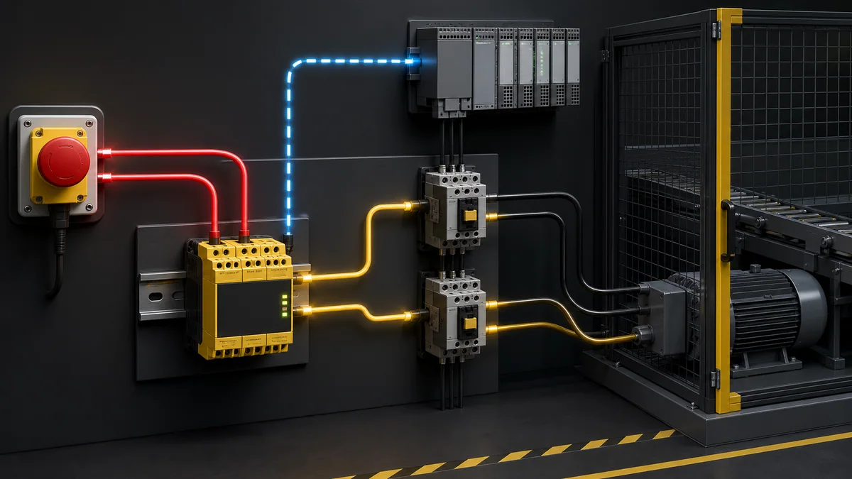
| Safety | E-stops, pull cords, guard switches, safety relay/PLC, safe drive functions | Read diagnostic status; do not replace the safety function |
| Motor power | Contactor, overload, VFD, brake, motor | Issue command and verify feedback |
| Detection | Photoeyes, prox sensors, encoders, jam switches | Debounce, track and diagnose |
| Sequence | Zones, merges, diverts and downstream handshakes | Coordinate starts, stops and product flow |
| Operator | Pushbuttons, selector, HMI and alarms | Present state and accept authorized requests |
| Supervisory | SCADA, historian and maintenance data | Publish diagnostics without making local control network-dependent |
Define the control contract before programming
For each conveyor drive, define:
| Signal | Direction | Meaning |
|---|---|---|
xRunRequest |
PLC → starter/VFD | Standard control requests motion |
xDriveReady |
starter/VFD → PLC | Drive can accept a command |
xRunningFeedback |
starter/VFD → PLC | Drive or verified auxiliary contact reports running |
xDriveFault |
starter/VFD → PLC | Drive has an active fault |
xSafetyHealthy |
safety system → PLC | Diagnostic indication only; not the safety function |
xDownstreamAvailable |
sequence → zone | Next zone can receive product |
xProductAtExit |
sensor → PLC | Product occupies the discharge sensor |
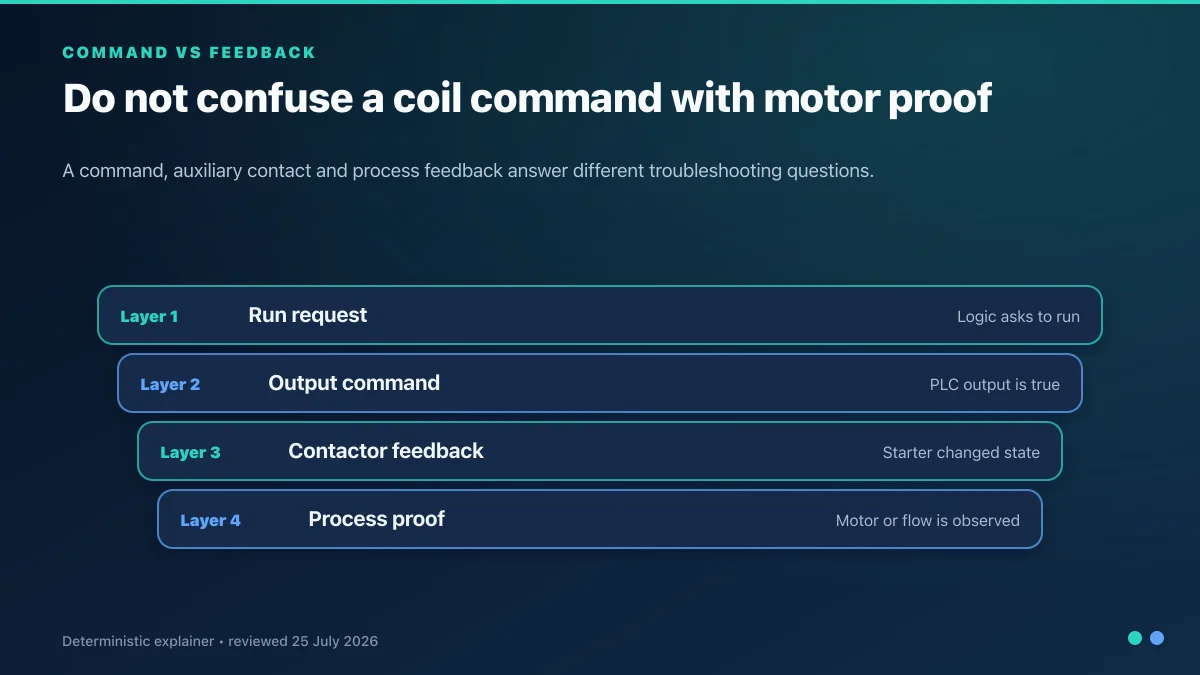
Then write the acceptance condition for each signal. “Motor running” might mean a VFD status bit, contactor auxiliary contact, zero-speed switch or measured encoder motion. Those are not equivalent.
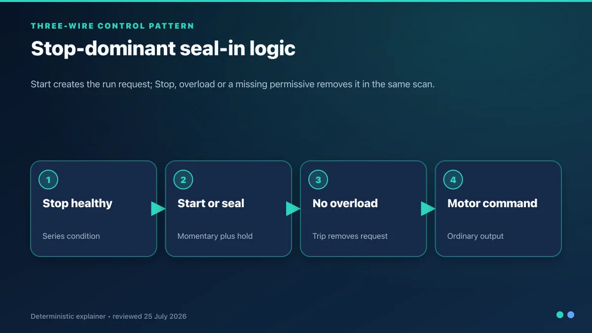
Stop-dominant motor logic
The command must drop when stop, fault, lost permissive or mode change requires it. A restart should require a new deliberate request unless the functional design explicitly justifies automatic recovery.
xReady :=
    xAutoMode
    AND xSafetyHealthy
    AND xDriveReady
    AND NOT xDriveFault
    AND xDownstreamAvailable;

IF xStopPB OR NOT xReady THEN
    xRunLatched := FALSE;
ELSIF xStartPB THEN
    xRunLatched := TRUE;
END_IF;

xRunRequest := xRunLatched AND xReady;

tonRunProof(
    IN := xRunRequest AND NOT xRunningFeedback,
    PT := T#2S
);

xStartFail := tonRunProof.Q;
The two-second timeout is an example test value, not a design recommendation. Set it from drive behavior, contactor pickup, brake release and process risk.
VFD integration
A VFD interface needs more than speed reference:
- run/stop command;
- drive ready and active status;
- fault code and fault present;
- commanded and actual speed;
- communications health;
- local/remote ownership;
- safe-torque-off diagnostic status where applicable; and
- reset request with edge and authorization control.
Network or hardwired?
| Interface | Strength | Limitation |
|---|---|---|
| Hardwired run plus analog speed | Simple failure boundary and familiar commissioning | Less diagnostic detail; analog scaling and wiring drift |
| Industrial network | Rich status, speed, current and diagnostic data | Switch, addressing, configuration and communications become dependencies |
| Hybrid | Hardwired critical command with network diagnostics | More design and test effort |
Select the interface from the risk assessment, process response and maintenance model. Do not assume that a networked command is either inherently safer or less safe.
Scale a speed reference explicitly
If the PLC command is 0–100% and the drive network reference is 0–16,384:
rSpeedPct := LIMIT(0.0, rOperatorSpeedPct, 100.0);
iDriveReference := REAL_TO_INT((rSpeedPct / 100.0) * 16384.0);
Record the units and range at both ends. Test 0%, minimum operating speed, 50%, 100%, out-of-range input and communications loss.
Product detection and tracking
Debounce sensors without hiding real products
Use an on-delay only when the minimum product dwell time is known:
tonEntryDebounce(
    IN := xEntryPhotoeye,
    PT := T#30MS
);

xEntryStable := tonEntryDebounce.Q;
rtrigEntry(CLK := xEntryStable);
The 30 ms value is an example. Calculate sensor dwell from product length and maximum belt speed, then test the smallest legitimate product and the shortest gap.
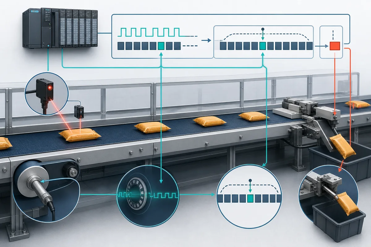
Track product by events, not assumptions
For a simple conveyor, count a product on a rising edge at entry and remove it at exit:
rtrigEntry(CLK := xEntryStable);
rtrigExit(CLK := xExitStable);

IF rtrigEntry.Q THEN
    diInCount := diInCount + 1;
END_IF;

IF rtrigExit.Q THEN
    diOutCount := diOutCount + 1;
END_IF;

diProductsOnConveyor := diInCount - diOutCount;
xTrackingMismatch := diProductsOnConveyor < 0
    OR diProductsOnConveyor > cdiMaxProducts;
For sorting, store a product record in a FIFO with destination, quality result and tracking ID. Shift or advance it only on a proved conveyor movement event. Define what happens after a stop, manual jog, sensor failure and product removal.
Three-zone zero-pressure accumulation example
For zones 1–3, run a zone when it contains product and the next zone can accept it:
xZone3Available := NOT xZone3Occupied OR xDischargeReady;
xZone2Available := NOT xZone2Occupied OR xZone3Available;
xZone1Available := NOT xZone1Occupied OR xZone2Available;

xZone3RunRequest :=
    xAutoPermissive
    AND xZone3Occupied
    AND xDischargeReady;

xZone2RunRequest :=
    xAutoPermissive
    AND xZone2Occupied
    AND xZone3Available;

xZone1RunRequest :=
    xAutoPermissive
    AND xZone1Occupied
    AND xZone2Available;
This teaching example omits transfer overlap, sensor placement, product length, coast distance and drive feedback. A production program usually needs a state per zone:
Empty → Receiving → Occupied → Releasing → Empty
                       ↘ Faulted
Each transfer should have a maximum expected time and a destination proof. If Zone 2 releases but Zone 3 never proves receipt, stop upstream feed and raise a diagnostic that names the failed transfer.
Startup and shutdown sequence
For a conveyor train:
- Prove the discharge machine is ready.
- Start the furthest downstream conveyor.
- Prove its running feedback.
- Start the next upstream conveyor.
- Continue toward the infeed.
For a normal stop:
- Stop accepting new product.
- Stop the furthest upstream feed.
- Allow downstream conveyors to clear as designed.
- Stop downstream sections after clear proof or a justified timeout.
An emergency stop is different. Its behavior comes from the risk assessment and safety design, not from a production clear-out sequence.
Conveyor safety boundary
The standard PLC sequence must not be presented as the emergency-stop function. ISO 13850:2015 specifies principles for emergency-stop functions, while electrical realization is addressed by the applicable machinery electrical standard. In the United States, OSHA 1910.147 covers hazardous-energy control during servicing; OSHA specifically uses a jammed conveyor as an example of hazardous unexpected release.
At minimum, the project safety process must address:
- accessible emergency-stop and pull-cord devices;
- guard and access-point hazards;
- stored mechanical, pneumatic and gravitational energy;
- restart prevention and manual reset behavior;
- stopping time and coast distance;
- safe drive functions where selected;
- lockout/tagout for jam clearing and servicing; and
- validation of every safety device and fault response.
Fault model and recovery
Use specific faults rather than one ConveyorFault bit:
| Fault | Detection | Recovery requirement |
|---|---|---|
| Failed to start | Command on, no running proof before timeout | Stop affected/upstream zones; inspect drive path |
| Unexpected running | Running proof without command | Remove standard request; follow safe response |
| Transfer timeout | Source released, destination not proved | Stop feed; inspect product/sensor |
| Sensor blocked | Photoeye active longer than justified dwell | Diagnose jam, contamination or failed sensor |
| Tracking mismatch | Count/FIFO outside valid bounds | Stop sort decisions; controlled resynchronization |
| Network loss | Drive or remote I/O quality bad | Defined degraded state; no automatic restart |
| Overload/VFD trip | Protection reports fault | Correct physical cause before authorized reset |
Reset should clear a latched diagnostic only after the initiating condition is gone. It should not force a sensor, bypass a guard or automatically restart the conveyor.
Commissioning test matrix
| Test | Injection | Expected evidence |
|---|---|---|
| Normal start | Start with all permissives true | Downstream-first sequence and running proof |
| Start feedback failure | Block one run feedback | Timeout identifies the correct drive; upstream feed stops |
| Product transfer | Move one product through all zones | One entry, one exit, no count drift |
| Short product/gap | Run minimum product at maximum speed | Sensor filtering still detects valid events |
| Blocked exit | Hold final zone occupied | Upstream zones accumulate without collision |
| Sensor stuck on | Hold one photoeye active | Specific blocked-sensor or transfer diagnostic |
| Communications loss | Remove one networked drive/I/O path | Defined stop/degraded behavior and bad-quality display |
| Stop during transfer | Issue stop in each zone state | No unintended restart or duplicate tracking event |
| Power cycle | Restart with products present | State follows documented recovery/resync procedure |
| Safety validation | Qualified test of every safety device and fault | Separate signed safety evidence |
Practice the sequence in a simulator
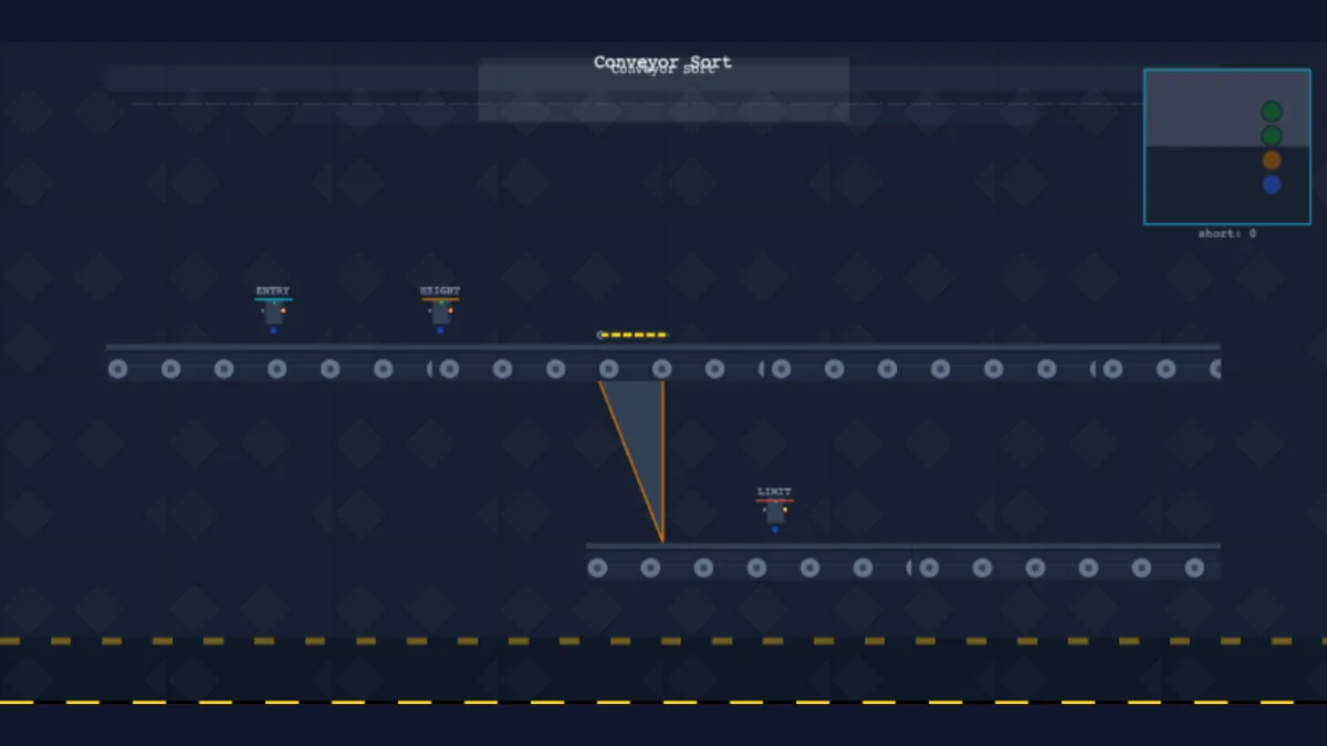
Open the conveyor exercises in PLC Simulation Software. Disclosure: PLCProgramming.io and PLC Simulation Software have common ownership. The product is a training simulator; it does not model the stopping time, safety performance, VFD firmware, electrical protection or mechanical hazards of a real conveyor.
Related practical guides:
- Motor start/stop ladder logic
- E-stop safety circuit and ladder logic
- Packaging machine PLC programming
- PLC troubleshooting workflow
- PLC scan cycle explained
Limitations
- Example timer and scaling values are placeholders to be replaced from project evidence.
- Product tracking examples omit encoder slip, physical removal and multiple-lane complexity.
- Safety design and validation must be performed by competent personnel under the applicable standards and law.
- A simulator result cannot certify stopping distance, guarding, electrical design or production suitability.
- Never clear a jam or service a conveyor based only on an HMI stop indication; follow the site energy-control procedure.
Frequently asked questions
Should conveyors start upstream or downstream first?
Normally start downstream first so material has somewhere to go, then prove each section before starting the next upstream conveyor. Validate the sequence for the actual process.
How do I detect a conveyor jam?
Use a defined transfer expectation: the source sensor releases a product and the destination sensor must detect it within a justified time. Combine this with drive current, speed or zero-motion evidence where appropriate.
Can the PLC emergency-stop the conveyor?
The standard PLC code in this article is not an emergency-stop function. Implement emergency stopping through the risk-assessed safety architecture and validate the complete input, logic, output and stopping behavior.
What should happen after a power failure?
Default to no unintended automatic restart. Reconcile product positions, controller state, drive state and safety reset before accepting a new start request.
How do I prevent product collisions?
Use occupied/available zone states, destination proof and transfer timeouts. Include product length, sensor placement, belt coast and maximum speed in the design.
Primary sources
- ISO 13850:2015 — Emergency stop function, principles for design
- OSHA 1910.147 — Control of hazardous energy
- OSHA: Control of hazardous energy overview
- OSHA 1918.64 — Powered conveyors
For warehouse-scale routing, load identity and transactional handshakes, continue with the automated storage and retrieval system PLC-controls guide.


