PLC Instrumentation: Sensors, Signals & Commissioning
Connect industrial instruments to a PLC from measurand and sensing principle through wiring, I/O, scaling, quality, loop checks and ordered fault diagnosis.
Review status: Editorially reviewed against current official metrology, transmitter-evaluation, PLC analog-I/O, HART, IO-Link, instrument-manufacturer and hazardous-energy sources; exact instrument, range, installation, loop, module, diagnostic, calibration, hazardous-area, control and safety requirements remain project-specific
Direct answer
PLC instrumentation is the complete evidence chain that turns a physical condition into a trustworthy controller value and then, where required, into a verified process response. The chain begins with a defined measurand such as pressure, temperature, flow, level, position or analytical composition. A sensing element responds to that quantity; a transmitter or signal conditioner converts the response; wiring or a digital network carries the signal; the PLC input module represents value plus channel status; scaling and validation create an engineering-unit tag; control, alarm, HMI and historian functions consume it; and a final element changes the process. Commissioning proves the chain from an approved stimulus to the intended result.
The PLC does not measure pressure, temperature or flow directly merely because a tag shows those units. It receives current, voltage, resistance, counts, frequency, contact state or structured digital data. Trust requires the instrument range and units, electrical interface, module configuration, raw/status representation, scaling ownership, data quality, timestamp or age, consumer behavior and an independent process check to agree.
For a linear 4–20 mA transmitter ranged 0–250 °C, 12 mA is the nominal midpoint: (12 − 4) / 16 = 0.5, so the scaled result is 125 °C. That calculation proves only the mapping. It does not prove the sensor is at 125 °C, the transmitter is correctly ranged, the loop is healthy or the PLC channel is reading the intended instrument. A loop check must test those boundaries explicitly.
Troubleshoot PLC instrumentation in order: process and sensing point, instrument identity/configuration, field power and signal, terminals/barriers, PLC channel configuration and status, raw data, scaling/validation, consumer tag and final response. Find the first boundary where expected and observed evidence disagree. Do not edit logic, zero a transmitter, force I/O or clear a diagnostic merely to make a number look plausible.
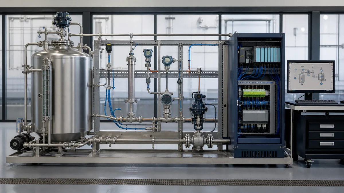
| Chain boundary | Design evidence | Runtime evidence | Typical failure class |
|---|---|---|---|
| process/measurand | quantity, units, reference, normal/upset range and decision | independent process observation or reference | the process model or measurement location is wrong |
| primary sensor | sensing principle, materials, installation and influence quantities | local physical condition and device diagnostics | fouling, blockage, drift, coating, damage or unsuitable principle |
| transmitter | exact device/revision, range, units, damping, output and fail behavior | local PV, configuration and status | wrong LRV/URV, unit, zero, mode or mapping |
| field interface | loop voltage, topology, barriers, cable, grounding and network profile | measured signal or link/status under approved procedure | lost power, open circuit, polarity, burden, interference or stale data |
| PLC input | module/channel, range, filter, update and diagnostics | raw value, channel status and module state | wrong channel/range, open wire, overrange or failed connection |
| conversion | formula, data types, limits, quality/age and one owner | intermediate and final engineering values | double scaling, integer truncation, wrong unit or accepted bad quality |
| consumer/final element | alarm, control, HMI, historian, output and safe-state contract | command, feedback and process response | correct value used incorrectly or command not achieved |
Define the instrument and PLC boundary
Start with the decision, not the signal type
An instrumentation specification should name what the control system must know and why. “AI-3 is 4–20 mA” is an electrical detail, not a measurement requirement. A useful definition includes the measurand, range, reference and units; normal, startup, cleaning, shutdown and upset states; required accuracy or uncertainty and response; environmental and process conditions; alarm/control/totalization use; and the consequence of missing, stale or wrong data.
Pressure must state gauge, absolute or differential reference. Temperature must state the sensing location, expected gradients, response time and whether the range suits an RTD, thermocouple or transmitter. Flow must distinguish mass, actual volume, normalized volume, velocity or total. Level must define datum, continuous versus point detection, interface, innage/ullage and whether volume or mass is derived. A vague tag can produce a correct electrical signal representing the wrong physical question.
| Decision surface | Questions that must be answered | Why the PLC cannot infer it |
|---|---|---|
| control | what variable is controlled, at what unit/range and response? | a raw count contains no process objective |
| alarm | what condition, persistence, quality state and operator response? | a limit alone does not define bad/stale-data behavior |
| totalization | rate basis, time basis, reset, retention and validity? | integrating an invalid or mismatched rate gives a plausible wrong total |
| protection | what independent risk-reduction function is required? | ordinary input/logic is not automatically a safety function |
| maintenance | what local, loop, channel and process evidence localizes failure? | one HMI number hides the boundary that failed |
Separate measurement, control and safety claims
A normal process transmitter can provide an excellent control value, but that does not make its PLC threshold an independent trip. Shared taps, power, wiring, I/O, controller, software, output, valve and human response can defeat both normal control and an alleged protective action. The risk assessment and applicable functional-safety, burner, machinery or overfill framework determine architecture, independence, diagnostics and proof testing. Do not assign a safety integrity claim from a generic page.
Select the sensing principle from the process
Pressure, temperature, flow and level are different jobs
Instrument selection begins with the process envelope and installation, then the output/interface. Choosing “a 4–20 mA sensor” reverses that order. Many instrument families can produce the same current while responding to different physics and failure modes.
| Measurand | Common instrument families | Selection boundaries | Frequent commissioning error |
|---|---|---|---|
| pressure | gauge, absolute or differential transmitter; switch | reference, static/overpressure, media, seals, impulse lines and dynamics | gauge/absolute mismatch or installation head hidden in software zero |
| temperature | RTD, thermocouple, thermistor, head/rail transmitter | range, accuracy, response, lead compensation, junction and environment | wrong sensor type/wiring or duplicate cold-junction/linearization assumptions |
| flow | magnetic, Coriolis, DP, vortex, ultrasonic, turbine or positive displacement | mass/volume basis, fluid properties, pipe state/profile, range and pressure loss | square-root or compensation applied twice; full-pipe condition ignored |
| level | radar, guided wave, ultrasonic, hydrostatic/DP, capacitance or float | datum, density/dielectric, vapor, foam, dust, nozzles, geometry and interface | distance treated as level or linear percentage treated as vessel volume |
| discrete state | proximity, photoelectric, pressure/level switch or limit device | target/material, range, output type, response, contamination and failure state | PNP/NPN or sourcing/sinking mismatch and no feedback supervision |
| analytical | pH, conductivity, dissolved oxygen, gas or composition analyzer | sample conditioning, calibration, temperature compensation and maintenance | PLC scaled correctly while sample system or sensor chemistry is invalid |
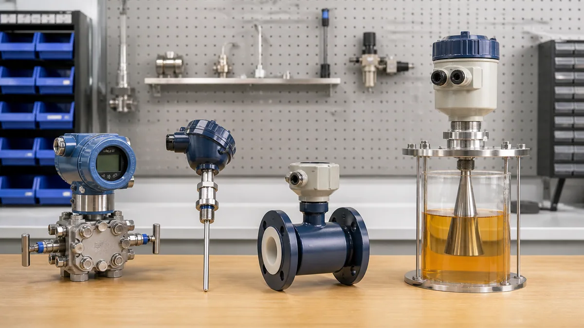
The pressure, flow and level measurement guide owns the detailed technology matrices, DP flow and hydrostatic calculations, level-to-volume treatment and selection evidence. The industrial sensor guide covers discrete sensing families. This hub preserves their boundaries instead of repeating shallow versions.
Choose the signal and PLC interface
Map information needs to an electrical or digital contract
4–20 mA is widely used because the current is carried through the series loop and 4 mA provides a live zero for the nominal measurement span. Its reliability still depends on sufficient loop voltage after transmitter, barrier, wire and input burden; correct active/passive roles and polarity; common-mode/isolation limits; and compatible diagnostic behavior. 0–10 V uses a voltage reference and has different drop, common-mode, impedance and interference concerns. They are not interchangeable through scaling alone.
Direct RTD or thermocouple modules perform sensor-specific excitation or conversion. Pulse/frequency inputs can represent speed, rate or total, but require compatible levels, frequency limits, edge behavior, counter handling and a controlled K-factor. HART can add identity, configuration, variables and status over a current loop when every host/gateway boundary supports and maps it. IO-Link and fieldbus/Ethernet profiles can carry multiple values and diagnostics, but identity, process-data layout, units, quality, update and replacement behavior must be engineered.
| Interface | Information carried | PLC evidence required | Main design trap |
|---|---|---|---|
| discrete contact/solid state | state, sometimes diagnostic channels | input voltage/current, sourcing/sinking, raw state and channel status | using contact symbolism as proof of physical normal/fail behavior |
| 4–20 mA | one primary analog value plus configured diagnostic range; optional HART | loop topology/budget, measured current, raw/status and scaling | applying universal fault thresholds or hiding an open loop by clamping |
| 0–10 V or ±10 V | analog potential relative to defined reference | source/load/common-mode compatibility and raw/status | shared-reference noise, voltage drop or wrong bipolar/unipolar range |
| RTD/thermocouple | resistance or thermoelectric voltage interpreted by module | exact sensor/wire type, compensation, range and channel diagnostics | wrong connection or sensor type appears as plausible temperature |
| pulse/frequency | events or frequency proportional to rate/position | electrical interface, count/frequency, time base and overflow handling | missed pulses, wrong K-factor or retained total reset unexpectedly |
| HART | analog PV plus supported digital variables/status/configuration | device/host revision, mapped variables, status and change record | assuming diagnostics reach the PLC because the transmitter supports them |
| IO-Link | cyclic process data, value status, identity, parameters and events | master/port mode, IODD identity, byte map, update and event evidence | wrong device/profile or silent byte/engineering-unit mapping |
| fieldbus/Ethernet | profile-defined values, status and device data | identity, profile, connection state, unit/quality and data age | stale or substituted data remains numerically credible |
The PLC analog I/O guide owns current/voltage topology, module raw formats, resolution versus accuracy, filtering and detailed output behavior. The IO-Link PLC guide and OPC UA PLC guide own those digital boundaries.
Wire and scale a 4–20 mA input
Prove the loop before applying the formula
A common two-wire loop includes a DC source, loop-powered transmitter, compatible PLC current input and the series conductors/terminals/barriers between them. The exact order can vary, but the same current flows around a healthy series loop. Verify the manufacturer diagrams for whether the input supplies loop power or expects an external source, the accepted common-mode/isolation, input burden and grounding/shield arrangement.
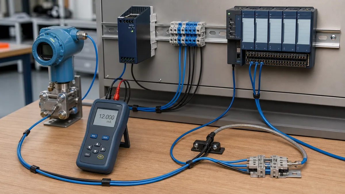
For a linear transmitter with lower range value LRV, upper range value URV and measured current I:
PV = LRV + ((I − 4 mA) / 16 mA) × (URV − LRV)
For a 0–250 °C range:
| Test current | Fraction of nominal span | Expected temperature | What this point can expose |
|---|---|---|---|
| 4 mA | 0 | 0 °C | lower endpoint, zero offset and range ownership |
| 8 mA | 0.25 | 62.5 °C | quarter-span scaling and data-type precision |
| 12 mA | 0.50 | 125 °C | midpoint, slope and duplicate scaling |
| 16 mA | 0.75 | 187.5 °C | upper-span linearity clue |
| 20 mA | 1.00 | 250 °C | upper endpoint and clamp/overrange boundary |
If the module supplies a raw count rather than milliamps, use the configured raw low/high endpoints:
EU = EUlow + ((Raw − RawLow) / (RawHigh − RawLow)) × (EUhigh − EUlow)
Keep the intermediate arithmetic in a type that preserves the needed precision. Test at least low, midpoint and high; five points help distinguish offset, slope and nonlinearity clues. Apply channel quality before trusting or clamping the value. Retain the unclamped diagnostic result so an open circuit or overrange does not masquerade as a valid endpoint.
These checks verify the electrical and software mapping exercised. Injecting 12 mA at the cabinet does not calibrate the sensor, validate its process installation or prove the field cable upstream of the injection point.
Design the PLC measurement data contract
Carry value, unit, quality and age together
A trustworthy measurement tag is more than a floating-point number. It should identify the engineering value and unit; raw or source value; device/channel quality; data age or update evidence where applicable; configured range; simulation/substitution/maintenance state; and reason for rejection, limitation or fallback. The exact structure depends on the controller and architecture, but consumers need a common policy.
| Data field | Purpose | Defect it prevents |
|---|---|---|
Value |
validated engineering-unit measurement | every consumer invents separate scaling |
Unit or controlled metadata |
physical meaning and conversion basis | pressure/temperature/flow basis silently changes |
Raw |
source value for diagnosis | scaling fault cannot be separated from input fault |
Quality |
good/bad/uncertain or project-specific validity | plausible bad value drives control or alarm |
Reason |
open wire, overrange, stale, maintenance or validation reason | one opaque bad bit prevents ordered diagnosis |
Age/timestamp |
freshness of digital/gateway value | frozen or stale value remains accepted |
RangeLow/High or revision reference |
active scaling contract | transmitter rerange and PLC constants diverge |
Mode |
normal, simulated, substituted, manual or maintenance | test data leaks into production decisions |
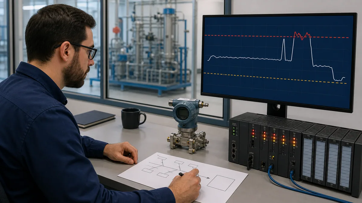
Define consumer behavior for invalid data
There is no universal safe response to bad instrumentation data. A display may show the last value with a clear stale/bad indication; an alarm calculation may enter a dedicated invalid state; a controller may hold, transfer to manual, use a bounded fallback or drive a defined safe response; a totalizer should normally stop integrating invalid input and expose why. These decisions come from the process and hazard analysis, not from a generic IF bad THEN Value := 0 rule. Zero is often a valid and dangerous-looking process condition.
Filtering also changes the contract. Input-module filtering, transmitter damping, PLC filters and HMI/historian smoothing can stack. Record the owner, time constant/update and diagnostic impact of each layer. Do not filter before preserving raw evidence, and do not use damping to hide electrical interference or an unstable process.
Commission the loop end to end
Distinguish calibration, verification and loop checking
Calibration establishes a relationship between indication and a traceable reference under stated conditions and uncertainty; adjustment changes the device; verification determines whether results meet defined acceptance criteria; a loop check proves the installed path and functional mapping. A calibration label does not prove the PLC range, channel, scaling, HMI, alarm or final element.
Before work, approve the instrument index and I/O list, P&ID/process schematic, data sheet, exact device and range, installation and wiring/network records, I/O configuration, scaling/quality policy, alarm/control cause and effect, reference equipment and tolerances. Define isolation, depressurization, electrical safe work, bypass/force authority, observers, abort conditions and restoration.

| Commissioning gate | Action | Pass evidence |
|---|---|---|
| document/identity | match tag, service, device, range, units, firmware/configuration and channel | controlled records match physical and online identity |
| installation | inspect location, orientation, process connection, impulse/sample path, materials and environment | installation meets exact device/project requirements |
| field interface | verify power, topology, barriers, polarity, terminations, shielding/grounding or digital link | expected electrical/link evidence with no unresolved diagnostic |
| input configuration | verify module/channel/range/filter/update and data representation | configured contract matches instrument output and acceptance record |
| point check | apply approved low/mid/high or suitable physical/reference points | as-found error within tolerance or controlled adjustment/retest recorded |
| quality/fault states | exercise defined open, over/underrange, stale, maintenance or device states where safe | PLC, HMI, alarm and control respond as specified |
| functional response | verify alarm, interlock/control, output, feedback and process result | cause-and-effect result observed with timestamps |
| restoration | remove simulations/bypasses/forces, restore connections/modes and archive state | as-left configuration, open deviations and approval recorded |
Keep an as-found/as-left record: tag and device identity, range/units, reference and uncertainty, environmental/process condition, each applied/observed point, PLC raw/status and scaled value, adjustment, alarm/control result, personnel/time and restoration. NIST’s traceability guidance emphasizes that traceability belongs to a measurement result through a documented chain; it does not by itself prove that uncertainty is fit for the process decision.
Troubleshoot PLC instrumentation in a fixed order
Find the first boundary that disagrees
Start with the symptom and expected state. Capture the time, process mode, local instrument reading/status, field signal or link state, PLC module/channel status, raw and engineering tags, quality/age, control command, output feedback and independent process evidence. Change one controlled condition at a time.
| Symptom | First discriminating comparison | Likely boundaries | Avoid |
|---|---|---|---|
| local PV correct, PLC value wrong | local output/configuration versus measured signal and PLC raw/status | output mapping, loop power/wiring/barrier, input range/channel or scaling | recalibrating the sensor before locating divergence |
| PLC raw correct, engineering value wrong | raw endpoints versus scaling constants/types/units | duplicate conversion, wrong range, integer math or stale configuration | changing transmitter range to match bad code |
| PLC value frozen but plausible | local changing PV versus raw/status/age and task/gateway updates | blocked sensing path, device hold, lost update, stopped mapping or HMI cache | accepting in-range as proof of health |
| noisy when motor/drive runs | aligned raw trend versus switching, supply/common and independent reference | coupling, grounding/shielding, routing, shared supply or real vibration | adding damping before proving the source |
| alarm occurs but process is normal | local/reference versus PLC quality, range, unit and alarm persistence | instrument fault, scaling, stale/bad handling or alarm design | widening the limit until nuisance stops |
| output command changes, process does not | PLC output status/physical signal, receiver indication, actuator position and process feedback | module power/load, output wiring, receiver range/mode, mechanics or process path | forcing higher output without feedback evidence |
| several loops fail together | shared power, barrier, I/O module, network, cabinet/environment and timestamps | common dependency rather than multiple sensor failures | replacing instruments one by one |
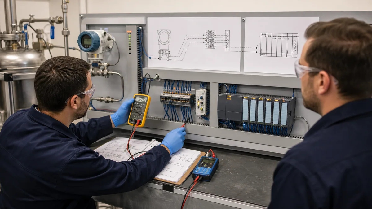
If several loops share the same bias, noise or failure time, look for common dependencies: power supply, reference/common, barrier chassis, analog module, network adapter, cabinet temperature/moisture, grounding/shield work, firmware/configuration deployment or a shared calculation library. Correlation does not prove cause, but it selects the next controlled comparison better than replacing multiple devices.
Build a practical PLC instrumentation learning path
Progress from measurement to controlled diagnosis
An instrumentation learner should not begin with a library of formulas detached from hardware. Use a staged path with an observable deliverable.
| Stage | Skill | Practical deliverable |
|---|---|---|
| 1 | quantities, units, range/span, accuracy, uncertainty and traceability | define one measurand and acceptance statement |
| 2 | pressure, temperature, flow, level and discrete sensing principles | justify a sensor family against process constraints |
| 3 | 24 VDC, contacts, sourcing/sinking, current/voltage and signal isolation | draw and review an exact manual-based training loop |
| 4 | PLC channel configuration, raw data, scaling and data types | pass low/mid/high mapping with units and status |
| 5 | quality, age, filtering, alarm and control consumer behavior | fault-state cause-and-effect matrix |
| 6 | calibration concepts, loop check and restoration | as-found/as-left training record |
| 7 | fault diagnosis across shared dependencies and final elements | seeded-fault report citing first divergent evidence |
Use the instrumentation training product path for browser-based measurement, scaling and diagnostic practice, then repeat exact transmitter, module, wiring, process and safety checks in an approved lab or site procedure. Ownership disclosure: PLC Programming IO and PLC Simulation Software are operated by the same publisher. The simulator is a practice layer, not a calibrator, vendor PLC, process model or commissioning approval.
Use the specialist instrumentation resources
This page owns the broad “PLC instrumentation” answer and routes deeper tasks to narrower canonical owners:
| Task | Canonical resource | What it owns |
|---|---|---|
| select pressure, flow or level technology | Pressure, flow and level measurement | physical models, selection matrices, worked DP/hydrostatic/volume examples |
| wire, scale and diagnose analog I/O | PLC analog I/O signals | current/voltage topology, raw formats, resolution, output and fault evidence |
| calculate a linear input quickly | 4–20 mA scaling calculator | endpoint calculation with explicit range inputs |
| understand current-loop hardware | 4–20 mA current loop | source/receiver roles, loop power and wiring concepts |
| run a commissioning loop check | Loop-check procedure | field-to-control-room verification and restoration record |
| select and connect smart sensors | IO-Link PLC guide | master/port/IODD/process-data/replacement evidence |
| select discrete sensors | Industrial sensor types | sensing principle and discrete-input selection |
| tune the controller after the measurement is trustworthy | PLC PID tuning | loop response, tuning method and operational limits |
Answer map for search and AI-assisted troubleshooting
| User or AI query | Concise answer | Qualification that must travel with it |
|---|---|---|
| What is PLC instrumentation? | It is the end-to-end chain from physical measurand and instrument through signal, PLC I/O, scaling/quality and final process use. | A PLC tag is not direct proof of the physical quantity. |
| What instruments connect to a PLC? | Pressure, temperature, flow, level, analytical and discrete devices connect through compatible current, voltage, resistance, pulse, contact or digital interfaces. | Select from process and safety requirements before interface convenience. |
| How do I scale 4–20 mA? | Map 4 mA to the engineering lower endpoint and 20 mA to the upper endpoint using a two-point linear equation. | Verify actual transmitter range, module raw endpoints and channel quality. |
| What should 12 mA equal for 0–250 °C? | Nominally 125 °C because 12 mA is 50% of the 4–20 mA span. | This proves mapping only, not sensor temperature or calibration. |
| Why does the PLC disagree with the transmitter? | Compare transmitter PV/output, physical loop signal, PLC raw/status, scaling, units and data age to find the first mismatch. | Do not adjust or rerange until the failed boundary is identified. |
| Is a loop check the same as calibration? | No. Calibration relates indication to a reference; a loop check proves the installed signal and functional path. | Define the exact procedure, reference and acceptance criteria. |
| Should bad analog quality become zero? | Not automatically; zero may be a valid process value. Preserve bad quality and select consumer behavior from process risk. | Display, alarm, control and totalization may need different responses. |
| Can PLC instrumentation be learned in a simulator? | Scaling, logic, data quality and fault reasoning can be practised within the simulator’s scope. | Real wiring, instrument physics, calibration, process and safety require approved equipment and procedures. |
Frequently asked questions
What is the difference between instrumentation and PLC programming?
Instrumentation defines and acquires trustworthy information about the process and operates final elements; PLC programming transforms inputs into control, alarm, sequence and output behavior. The disciplines overlap at I/O configuration, scaling, quality, diagnostics, control strategy and commissioning. Neither can compensate safely for an undefined process measurement or uncontrolled logic.
Which instrumentation signals can a PLC read?
A suitably equipped PLC can read discrete voltage/contact states, current and voltage analog signals, RTDs, thermocouples, pulse/frequency/count signals and supported digital protocols. Capability depends on the exact module, sensor electrical interface, isolation/common-mode, range, data format and configuration.
How do I scale a 4–20 mA transmitter in a PLC?
Confirm transmitter LRV, URV and units plus module range/raw endpoints. For current I, use PV = LRV + ((I − 4) / 16) × (URV − LRV). Test multiple points and evaluate channel quality before clamping or control use.
Why is 4–20 mA used instead of 0–20 mA?
The nominal 4 mA live zero supports loop-powered transmitters and separates the normal lower endpoint from some lost-power/open-loop conditions. Exact below/above-range diagnostic behavior is device and input specific; do not apply one universal failure threshold.
What is an instrument loop check?
A loop check verifies the installed path from approved field stimulus or simulation through transmitter/signal, PLC raw/status and scaling to HMI, alarm, control or output response, followed by restoration. It complements rather than replaces calibration and process validation.
What is the difference between calibration and adjustment?
Calibration establishes the relationship between indication and a reference under stated conditions and uncertainty. Adjustment changes the device to improve its indication or output. Record as-found results before adjustment and as-left results afterward; do not call every check a calibration.
Why is a PLC analog value noisy?
The process may genuinely vary, or the signal may be affected by sensor dynamics, vibration, power/common coupling, grounding/shielding, routing, transmitter configuration, module range or filtering. Align raw trends with process and switching evidence before adding damping.
Why does a PLC instrument value freeze at a believable number?
Possible causes include a blocked sensing path, device hold/substitution, stale network or gateway data, failed mapping/task execution, retained software value or stopped HMI update. Compare local change, raw/status and age while applying an approved changing stimulus.
Can the same PLC transmitter be used for control and a safety trip?
Only when the risk assessment and applicable safety framework justify the architecture, independence, diagnostics, proof testing and final elements. Sharing the normal transmitter, tap, input, PLC or valve can create common-cause failure; ordinary control logic is not automatically a safety function.
How should I learn PLC instrumentation?
Progress from quantities and sensor principles to safe electrical interfaces, PLC channel configuration, scaling, data quality, loop checks and ordered diagnosis. Require practical deliverables at each stage, then transfer simulator learning to approved vendor software, instrument and process labs under qualified supervision.
Sources, review scope and limitations
This hub was reviewed on August 29, 2026. Standards, PLC modules, transmitter firmware/configuration, diagnostic conventions and training offerings change. Verify the exact adopted edition, device manual and site requirements.
- BIPM SI Brochure — authoritative SI quantity and unit framework.
- NIST Metrological Traceability — calibration-chain, uncertainty and fitness-for-purpose boundaries.
- IEC 62828-1:2026 — general procedures for evaluating industrial/process measurement transmitters.
- IEC 61298-1:2026 — general performance-evaluation context for process measurement/control devices outside the updated transmitter scope.
- NIST SP 800-82 Rev. 3 — operational-technology and control-system architecture/security context.
- ISA Technician Training — official instrumentation, troubleshooting, process-control and PLC technician topic map.
- Rockwell Automation Learning+: Control Instrumentation — official control-instrumentation course scope.
- Rockwell Automation PointMax Analog I/O Modules User Manual — channel configuration, range and diagnostic examples.
- Rockwell Automation ControlLogix High-Resolution Analog I/O User Manual — module tags, channel status and program/fault reactions.
- Siemens S7-1200 G2 System Manual — current analog ranges, representation and two-wire examples.
- Siemens S7-1500 Analog Value Processing — analog representation and processing concepts.
- Schneider Electric TM3 Analog I/O Diagnostics — product/range-specific channel status examples.
- NI 4–20 mA Current Loop Fundamentals — loop components, voltage budget, burden and isolation context.
- FieldComm Group HART Specifications and HART revision comparison — official protocol, variable/status and revision context.
- IO-Link Interface and System Specification V1.1.4 — official master/device, port and process-data interface scope.
- Emerson Rosemount 3051S Reference Manual — product-specific pressure, scaled-variable, DP flow and level examples.
- Emerson Rosemount 8750W Magnetic Flowmeter Reference Manual — product-specific flow installation and diagnostic conditions.
- Siemens SITRANS LR100 Operating Instructions — product-specific radar installation and false-echo context.
- OSHA 29 CFR 1910.147 and OSHA 29 CFR 1910.333 — hazardous-energy and electrical safe-work boundaries in their scope.
The six original generated figures are editorial abstractions, not manufacturer product images, instrument data sheets, P&IDs, terminal drawings, hazardous-area designs, calibration procedures or safety architectures. This page does not authorize opening process connections, applying pressure/temperature/electrical signals, defeating interlocks, forcing I/O, editing logic or energizing equipment. Use exact current manuals, approved drawings, suitable reference equipment and qualified instrumentation, electrical, process, controls and safety authority. Revalidate after changes to process, sensor, installation, instrument configuration, range/units, wiring/barrier, module, firmware, scaling/quality logic, alarm/control use, final element or protective architecture.
Browse the PLC instrumentation library
Use the broad hub to choose the boundary, then open the narrower owner for calculations, device selection, wiring or commissioning detail.
Signals and analog I/O
Pressure, temperature, flow and level
Sensors, calibration and commissioning
PLC Programming IO Editorial Team
Industrial automation education, references, and software testing
The PLC Programming IO Editorial Team publishes sourced industrial-automation education and documents how material is reviewed, tested, and corrected. A team byline means the publisher is responsible for the page; it does not represent a fictional person or imply an engineering licence.
Coverage:
- • PLC programming concepts and examples
- • Vendor software tutorials and comparisons
- • SCADA, HMI, protocols, and instrumentation
- • Training, careers, and reference material
Review standard:
- • Prefer primary and official sources
- • Record software versions when material
- • Separate tested facts from estimates
- • Publish material corrections
Important scope note
This site provides education, not project-specific engineering approval. Safety, code, and compliance decisions require a qualified person with access to the actual machine and jurisdiction.