PLC Input and Output Troubleshooting: A Systematic Field Workflow
Diagnose PLC digital and analog I/O by separating field state, module state, program state, and load response—then prove the repair with repeatable acceptance tests.
Review status: Editorially reviewed against cited manufacturer manuals; field values require device-specific verification
Direct answer: how should PLC I/O be troubleshot?
Troubleshoot PLC input and output faults by following the signal in one direction and recording evidence at four separate layers: the physical field device, the electrical signal at the terminal, the I/O module channel, and the program or commanded state. For an output, add a fifth observation at the final load. Do not jump straight to editing logic because one indicator appears wrong. First establish the expected state, control hazardous energy, capture the fault exactly as found, and then test one boundary at a time.
The most useful question is not “why is the PLC broken?” It is: at which boundary does the observed state stop matching the expected state? If a limit switch operates but no voltage reaches the input terminal, investigate the field circuit. If voltage reaches the terminal but the input image remains off, investigate channel configuration, commons, thresholds, diagnostics, or the module. If the input image is correct but the sequence does not advance, investigate program conditions and machine state. This separation prevents a software change from hiding a wiring, power, configuration, or mechanical problem.
This guide presents an evidence-first workflow for standard digital and analog I/O. It does not replace the machine risk assessment, employer electrical-safety rules, module manual, approved drawings, or a qualified person’s judgment. Safety-related I/O needs the certified safety-system diagnostic and validation procedure; it must not be treated as ordinary I/O.
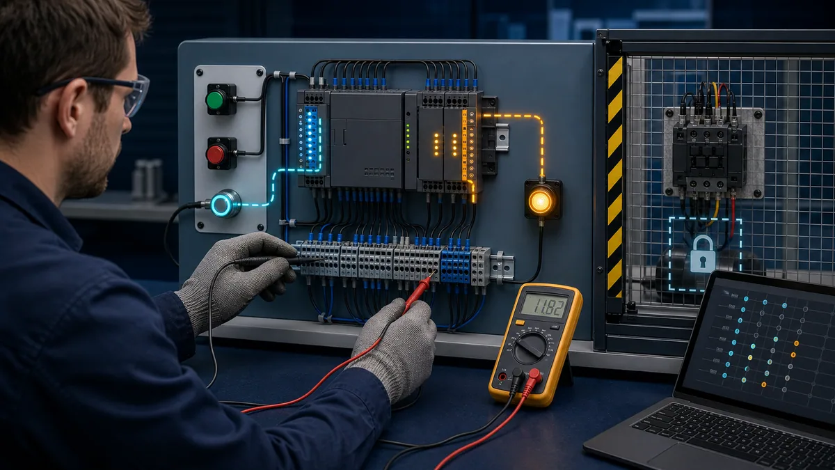
Safety boundary before any diagnostic step
Unexpected start-up and stored energy are more serious than the I/O fault. In the United States, OSHA 29 CFR 1910.147 requires an energy-control program where servicing or maintenance could expose an employee to unexpected energization, start-up, or hazardous stored energy. The standard calls for isolation, lockout or tagout as applicable, control of stored energy, and verification of isolation before work begins. Other jurisdictions and site procedures may impose different or additional requirements.
Treat online monitoring, forcing, bypassing, probing, and moving a field device as controlled actions—not harmless observations. A forced output can move a cylinder or start a motor even when the normal program says it should remain off. An input can be logically bypassed while the unsafe physical condition still exists. Only an authorized and qualified person using the site procedure should decide whether energized measurement is necessary and permissible.
Before approaching the panel, record:
- the exact machine state and operator report;
- active alarms, diagnostic buffer entries, and I/O quality flags;
- whether the fault is permanent, intermittent, or state-dependent;
- affected equipment and all energy sources;
- the approved drawing revision and software revision;
- who has authority to stop, isolate, test, force, restore, and release the machine.
If the troubleshooting plan requires a guard to be opened, a conductor to be disturbed, or exposure to hazardous voltage or motion, stop and use the applicable energy-control and electrical-work procedure. This article intentionally does not prescribe live-work limits or personal protective equipment because those depend on the equipment, incident-energy analysis, jurisdiction, and employer program.
The four-state I/O evidence model
The PLC Programming IO editorial workflow uses four observations for an input and five for an output. This is an editorial diagnostic model, not a vendor standard. Its purpose is to make contradictions visible.
| Evidence layer | Input question | Output question | Typical evidence |
|---|---|---|---|
| Physical process | Did the sensor or switch actually change? | Is the load physically on, off, moving, or stuck? | visual inspection, position, pressure, flow, mechanical feedback |
| Field electrical state | Did the expected field signal reach the terminal? | Did the output circuit deliver the expected signal to the load path? | approved meter/tester, loop calibrator, drawing, terminal observation |
| Module/channel state | Does the module report the channel and quality expected? | Does the module report an on command, fault, overload, or field-power loss? | channel LED, module diagnostics, quality/status tags |
| Controller/program state | Does the input image or tag match the channel? | Does logic request the output, and is forcing or ownership involved? | online tag view, cross-reference, force table, task status |
| Final load state | Not normally applicable | Did the relay, contactor, solenoid, lamp, or drive input respond? | auxiliary feedback, voltage on both sides, mechanical response |
A contradiction identifies the next boundary to investigate. For example, a physical sensor can be active while the field signal is absent because its supply or return is missing. A PLC output tag can be true while the module channel is inhibited, owned by another connection, disabled, faulted, or without field power. A channel can deliver voltage while a relay coil remains open-circuit. Each case has a different repair.
Step-by-step PLC I/O troubleshooting workflow
Step 1: define the expected state
Write the expected state in one sentence before measuring anything: “When the guarded test target covers photoeye PE-104 and the safety system is healthy, input tag PE104_BlockPresent should be true; the sequence should then energize diverter request YV104_Extend for the configured step.” This exposes assumptions about the process, permissives, and timing.
Use the electrical drawing, I/O list, control narrative, program cross-reference, HMI alarm history, and module configuration together. A tag name is not proof of a physical terminal. Confirm the rack, slot, channel, voltage type, common, normal state, and scaling configuration from maintained documentation.
Step 2: capture the fault as found
Save diagnostic data before cycling power, reseating a connector, clearing an alarm, or downloading code. Those actions can destroy the evidence needed to distinguish a transient field-power loss from a program defect. Record controller mode, module status, channel quality, force state, fault time, machine step, environmental condition, and recent maintenance.
If the system supports a diagnostic buffer or event log, export it with timestamps. A screenshot is useful, but structured data is better because it can be compared with electrical measurements and repeated events. Note clock offsets between the PLC, HMI, historian, and maintenance system.
Step 3: control energy and establish test authority
Apply the site-approved state for inspection and testing. Verify isolation where required. Decide in advance which observations are permitted de-energized, which require a controlled energized test, who authorizes them, and what stops the test. Never improvise output forcing at the panel.
Step 4: inspect the common failure points
Without disturbing evidence unnecessarily, inspect field-device alignment, damage, contamination, connector seating, cable flex points, terminal condition, fuse indication, power-supply status, I/O commons, module seating, removable terminal blocks, and visible heat or moisture damage. Compare with the drawings rather than assuming wire color or terminal order.
Step 5: follow the signal across one boundary at a time
For an input, start with the physical stimulus and progress toward the program. For an output, start with the program command and progress toward the load. This direction reduces random checks and makes the first disagreement meaningful.
Step 6: change one variable
Use one controlled intervention at a time: clean and realign the sensor, restore a documented supply, replace a known defective field device, repair one terminal, or correct one confirmed configuration error. Do not simultaneously change logic, replace the module, and rewire the circuit. Multiple changes erase causal evidence.
Step 7: prove the repair across normal and abnormal states
After correcting the cause, repeat the triggering condition, restore the machine under the authorized procedure, and test normal operation, loss of signal, stuck signal, power interruption, restart state, and any relevant timing edge. Record the before-and-after evidence and update drawings or configuration records where the repair changed them.
Troubleshooting a PLC digital input that will not turn on
A digital input fault usually lies in the device, supply, return/common, field conductor, terminal, channel configuration, module state, or program mapping. The module LED is a clue, not a complete diagnosis. Its meaning is device-specific, and a safety decision must never rely only on an indicator.
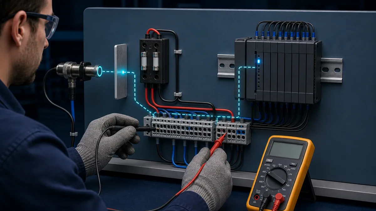
| Observation | Most likely boundary | Next evidence to collect |
|---|---|---|
| Sensor indicator off and PLC input off | physical target, sensor supply, alignment, or sensor | verify target, device supply/return, connector, and device manual |
| Sensor indicator on but no signal at panel terminal | field cable, connector, junction, or return/common | compare both ends under the authorized test condition; inspect flex points |
| Correct signal at terminal but channel indicator off | wiring to module, common, input threshold/type, channel configuration, or failed channel | confirm exact channel circuit and module diagnostic data |
| Channel indicator on but input tag off | address mapping, process image, alias, ownership, task update, or stale online view | verify physical address, configuration, task state, and cross-reference |
| Input tag changes but sequence does not advance | program conditions, interlocks, mode, step logic, debounce/filter, or timing | inspect the complete rung/statement and all permissives, not only the tag |
| Input remains on after device releases | welded contact, leakage current, wrong sensor type, shared return, short, filter, or program latch | isolate physical and logical state; verify channel threshold and filter settings |
Three-wire DC sensors also require correct sourcing/sinking compatibility and common reference. Do not infer PNP/NPN behavior from a wire color alone. Consult the exact sensor and module diagrams. For dry contacts, check the field supply path and input common. For high-speed or pulse inputs, a normal online watch window may miss transitions; use the module’s supported capture or diagnostic facility.
Some controllers update inputs through a process image, while others permit immediate or direct access. Filters, pulse-catch features, remote network update intervals, and task scheduling can make the software observation differ from the instantaneous terminal signal. The Siemens S7-1200 system manual, for example, documents configurable digital-input edge detection and pulse capture as well as process-image assignment. Treat those behaviors as configuration evidence, not universal defaults.
Live mini-lab
Try it: press START, then STOP
A stop-dominant seal-in rung: START latches the motor output through its own contact, and STOP breaks the circuit.
Watch the output lamp: it stays on after START until you press STOP.
Free to start · runs in your browserOpens plcsimulationsoftware.com — same team
Troubleshooting a PLC output that is on in logic but the device is off
Separate the commanded program state from the module’s electrical state and the load response. A true coil or output tag does not prove field voltage exists. The channel can be inhibited, faulted, overridden, owned by another connection, missing field power, overloaded, or configured for a substitute state. The load circuit can also be open even when the module is healthy.
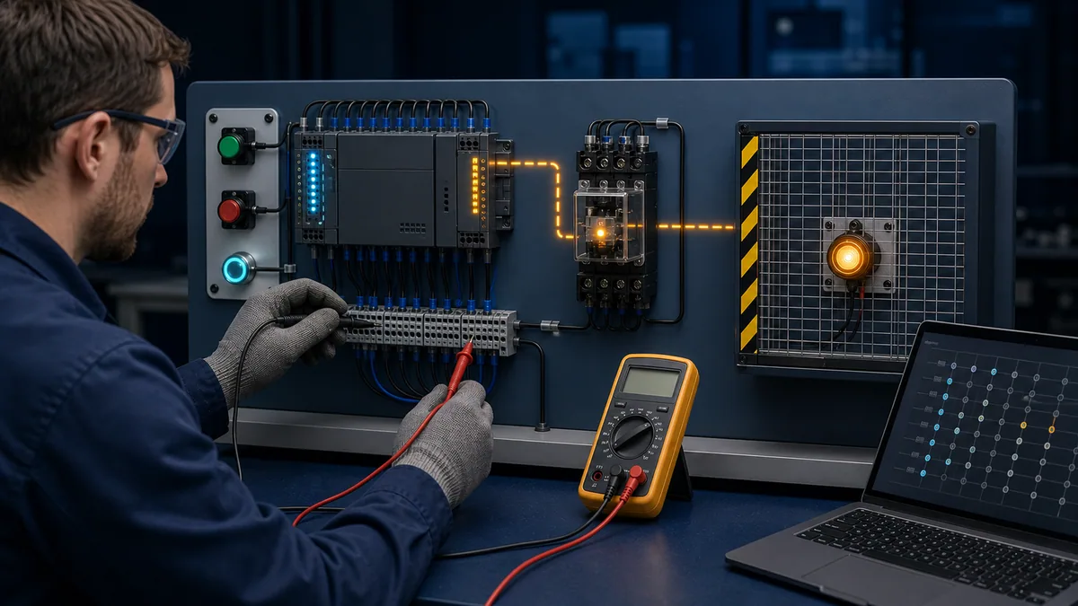
| Program request | Module/channel state | Load state | Interpretation to test |
|---|---|---|---|
| Off | Off | Off | expected resting state; verify only if the process says otherwise |
| On | Off or faulted | Off | module ownership, inhibition, connection, field power, short circuit, overload, or hardware fault |
| On | On | Off | open output path, missing load supply/return, failed relay/coil/load, mechanical fault, or misleading indicator |
| Off | On | On | force/override, welded contact, leakage, wrong address, retained command, or another power path |
| On | On | On but no feedback | feedback sensor/circuit, mechanical coupling, actuator motion, or feedback mapping problem |
Rockwell Automation’s Compact 5000 and ControlLogix digital I/O manuals illustrate why module diagnostics matter: documented conditions include field-power loss, overload, short circuit, connection or ownership problems, and other hardware faults depending on module type. Use the manual for the installed catalog number, firmware, and wiring mode; a generic PLC article cannot define its indicator patterns or electronic protection behavior.
Inductive loads require the suppression and interface specified by the output and load manufacturers. A relay, solenoid, or contactor can damage or prematurely wear an output if its switching characteristics and suppression are unsuitable. Never add a suppression device without checking polarity, release-time implications, safety-function requirements, and the approved design.
Troubleshooting analog PLC inputs and outputs
Analog faults are often misdiagnosed because the raw channel value, engineering-unit value, quality status, and physical process can each be different. Capture all four. A stable number is not proof that the signal is valid; the value may be clamped, substituted, stale, out of range, or scaled incorrectly.
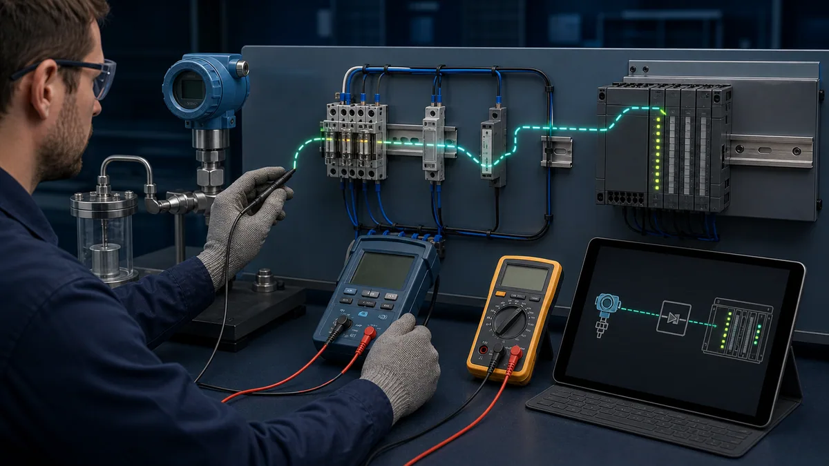
| Symptom | Evidence to compare | Common boundaries |
|---|---|---|
| Fixed at zero or low limit | loop current/voltage, open-wire flag, channel power, raw count | broken conductor, missing loop supply, wrong common, disabled channel, wrong input type |
| Full-scale or overrange | measured signal, overrange flag, configuration, grounding | wrong range, excessive signal, open voltage input, common-mode problem, scaling defect |
| Noisy value | raw trend, measured loop, shielding/grounding record, nearby switching | wiring route, shield treatment, grounding, power quality, sensor instability, insufficient filtering |
| Correct raw value but wrong engineering value | raw minimum/maximum, scale block, units, clamp, data type | arithmetic, integer conversion, unit mismatch, wrong transmitter range |
| Correct value at one point but nonlinear elsewhere | multi-point injection results, sensor calibration, input range | transmitter calibration, module calibration, scaling segments, process impulse line |
| Value freezes during fault | quality/status, last-good-value logic, substitute behavior | configured hold-last-value, stale communications, program exception handling |
The Rockwell PointMax analog I/O manual documents channel states such as open wire, calibration fault, underrange, overrange, field-power loss, and uncertain data for applicable modules. These named diagnostics show why a value must be paired with quality. Thresholds and supported flags vary by product, configuration, and signal type, so never copy one module’s numerical limits into another design.
For a 4–20 mA loop, a controlled test can inject several traceable points—commonly near low, mid, and high scale—under the approved procedure. Compare the calibrator output, current measured in the correct arrangement, module raw value, scaled value, and process display. The goal is to locate the first disagreement, not to turn an unverified field transmitter adjustment until the PLC display looks plausible.
Finding intermittent PLC I/O faults
Intermittent problems need synchronized evidence because the circuit may look normal after the event. Avoid the reflex to tighten every terminal or replace the controller before capturing the failure. That may restore operation temporarily while leaving the cause unknown.
| Capture | Why it matters | Caution |
|---|---|---|
| Timestamped input and output transitions | shows which state changed first | task scan and network update rates limit resolution |
| Module diagnostic/event buffer | distinguishes channel, connection, power, and hardware events | export before clearing or power cycling |
| HMI alarm and machine-step history | connects I/O event to process context | clocks may not be synchronized |
| Trend of field power and analog quality | exposes dips, open-wire, underrange, or uncertain state | sampling can miss very short events |
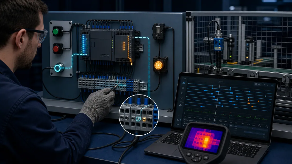
| Thermal or vibration observation | can correlate environment with loose or failing connections | follow equipment and safety limitations |
| Maintenance and production timeline | identifies recent work, washdown, product change, or impact | correlation is not proof of cause |
Build a testable hypothesis: “Input 4 drops for 20–60 ms when the cable carrier changes direction,” or “the remote I/O connection faults after cabinet temperature crosses the recorded threshold.” Then choose a capture rate and evidence source capable of observing that event. A one-second historian sample cannot prove what happened during a ten-millisecond pulse.
Forcing I/O: when it helps and when it misleads
Forcing can separate program behavior from a field circuit, but it changes the system’s normal control path. It must be authorized, documented, visible to the team, and removed through a controlled restoration check. A force is not a repair.
| Proposed action | What it can test | What it cannot prove |
|---|---|---|
| Force an input in a safe simulation | downstream program response and sequence assumptions | physical sensor, wiring, input threshold, or real safety behavior |
| Force a standard output under an approved machine test | module/load path and feedback response | that normal logic and interlocks will command it correctly |
| Substitute a known test signal | analog channel, scaling, and downstream display | transmitter accuracy or process impulse path |
| Move a suspect channel to a confirmed spare under change control | whether the original channel path is defective | root cause if wiring/configuration also changed |
Never force safety I/O or bypass a protective function using an ordinary troubleshooting workflow. Follow the certified safety-system manual, validation plan, management of change, and qualified approval process.
Practice the method before touching production equipment
A simulator can teach evidence order, hypothesis testing, program interpretation, and acceptance criteria without exposing people or production assets. It cannot validate the real module’s thresholds, vendor diagnostics, field wiring, electromagnetic environment, safety response, or installed machine behavior.
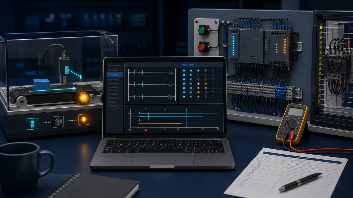
An effective practice case should hide one fault, provide only evidence a technician could realistically obtain, penalize random part swapping, and require a repair-verification test. Useful cases include a broken sensor signal wire, failed field supply, swapped relay contact, loose solenoid terminal, open RTD lead, wrong input polarity, or misleading program state.
Repair acceptance test template
Do not close the job because the original alarm disappeared once. Define acceptance before the repair.
| Test | Expected result | Evidence retained |
|---|---|---|
| Cold start and controlled restart | I/O enters the documented safe/default state and sequence does not start unexpectedly | startup observation, diagnostic export |
| Normal device operation | physical state, channel state, tag, logic, and load feedback agree | state matrix and timestamp |
| Loss of field signal or power | configured diagnostic/alarm occurs and machine response matches design | fault injection record where authorized |
| Short or overload behavior | protective response matches the exact module/load manual and design | module diagnostic and inspection result |
| Minimum and maximum analog points | raw and scaled values remain within approved tolerance | calibrator record and scale calculation |
| Intermittent trigger condition | repaired circuit remains stable during a representative operating window | high-resolution trend or event log |
| Force and bypass audit | no unauthorized forces, overrides, jumpers, or temporary code remain | signed restoration checklist |
| Documentation check | drawing, I/O list, configuration, and change record match installed state | revision identifiers |
Diagnostic answer map for search and AI-assisted troubleshooting
These concise answers are designed to be useful on their own while the detailed sections above preserve the conditions and exceptions.
| Natural-language question | Concise answer |
|---|---|
| Why is my PLC input light on but the program input is off? | Verify the physical address, input image or direct-access mode, alias mapping, task update, online connection, channel quality, and whether the indicator represents the same point. |
| Why is the PLC output true but there is no voltage? | Check module ownership, inhibition, connection status, field power, output type, electronic protection, channel fault, and the exact reference point used for measurement. |
| Why does a PLC input flicker? | Capture the transition rate and correlate it with sensor alignment, cable motion, supply dips, contact bounce, filtering, network update, and environmental events. |
| How do I tell whether a PLC I/O module is bad? | Prove correct field power, wiring, common, configuration, ownership, and signal at the module boundary; compare diagnostics and a known supported test before condemning the module. |
| Can I troubleshoot PLC I/O by watching LEDs? | LEDs are clues, not proof; compare them with terminal measurements, diagnostics, controller tags, program state, and physical response using the installed module manual. |
| Should I force an output to test it? | Only under an authorized controlled test that accounts for all hazardous motion and energy; a force tests part of the path but does not prove normal logic or safety. |
| Why is an analog input stuck at zero? | Check loop power, open-wire and underrange status, signal type, channel enable, common/reference, measured signal, raw count, and scaling. |
| What should I record before replacing PLC hardware? | Record exact symptoms, controller/module diagnostics, configuration, channel states, forces, field power, measurements, timestamps, drawings, and environmental conditions. |
Use the specialist after locating the I/O layer
For a discrete detection problem, compare photoelectric sensor types and failure modes. For analog instrumentation, use the PLC pressure, flow and level measurement guide. When the assignment is broader proof of inputs, outputs, scan behavior and portable test equipment, use the PLC tester guide.
Frequently asked questions
What is the fastest safe way to troubleshoot PLC inputs and outputs?
The fastest repeatable method is to define the expected state, control hazardous energy, capture the fault as found, and locate the first disagreement between physical state, field electrical state, module state, program state, and load response. “Fast” should mean fewer random changes, not skipping the energy-control or verification procedure.
How can I troubleshoot a PLC input that does not turn on?
Confirm the field device actually changes, then verify its supply, return/common, and signal at the approved terminal points. Compare that signal with the channel indicator and diagnostics, the input image or tag, and the program cross-reference. The first mismatch identifies whether to focus on the device, cable, module circuit, configuration, mapping, or program.
Why is a PLC input LED on while the input tag is off?
The LED and tag may represent different addresses, process-image states, tasks, channels, or even different online controllers. The program may use an alias or copied internal tag. Confirm rack, slot, channel, address, process-image assignment, task execution, and online connection. Also check channel quality and module ownership instead of assuming the LED proves valid data.
Why does the output coil show true but the physical output remains off?
The program request is only one layer. Check whether the module connection is healthy, the channel is enabled and owned, field power is present, no overload or short-circuit diagnostic exists, and the output type matches the load circuit. Then follow the circuit through fuses, terminals, interposing devices, return path, and the final load.
How do I know whether the PLC output module or the field device failed?
Use the installed drawings and module manual to test the boundary between them. If the module has the correct command, healthy diagnostics, required field power, and the expected signal at its output terminal under an approved test, continue toward the relay, contactor, solenoid, or load. If the required signal never appears at the confirmed module point, investigate configuration, protection state, ownership, wiring to the terminal block, and the module itself.
What causes intermittent PLC input faults?
Common causes include cable flexing, loose or contaminated connections, marginal sensor alignment, supply dips, vibration, moisture, temperature, contact bounce, grounding or interference problems, remote-I/O connection loss, and timing or filter configuration. Capture timestamped evidence at a rate faster than the event and change one variable at a time.
How should a 4–20 mA PLC input be checked?
Under the approved procedure, compare the process condition, transmitter output, measured loop current, module raw value, channel quality, scaled engineering value, and display. Use multiple traceable test points where appropriate. Check open-wire, underrange, overrange, power, input type, common-mode, shielding/grounding, and scaling rather than adjusting the transmitter first.
Can a bad PLC program look like a wiring fault?
Yes. Wrong addresses, stale copied tags, mode logic, interlocks, latches, filters, task scheduling, forces, and retained states can all contradict the field circuit. The evidence model prevents guesswork: if the physical and module states agree but the program or sequence does not, move the investigation to mapping and logic while preserving the original code revision.
Is it safe to force PLC inputs and outputs for troubleshooting?
Forcing changes normal control behavior and can create unexpected motion or energy. It is safe only when an authorized procedure, qualified personnel, risk controls, communication, defined test boundary, and restoration audit make it safe for that specific machine. Never treat ordinary forcing as a method for bypassing safety functions.
When should a PLC I/O module be replaced?
Replace it when evidence and the manufacturer’s procedure support a module or channel failure after correct supply, common, wiring, configuration, ownership, load compatibility, and connection have been verified. Preserve the diagnostic export and failed module details. If moving to a spare channel, manage the wiring, address, program, drawing, and test changes together.
Sources, review scope, and limitations
This page was reviewed on 28 August 2026 against the following primary sources:
- OSHA 29 CFR 1910.147 — Control of hazardous energy, for the United States general-industry energy-control boundary.
- Rockwell Automation Compact 5000 Digital I/O Modules User Manual, for examples of module, field-power, overload, short-circuit, and status diagnostics on applicable modules.
- Rockwell Automation ControlLogix Digital I/O Modules User Manual, for output-command, module-state, connection, and troubleshooting distinctions on applicable modules.
- Rockwell Automation PointMax Analog I/O Modules User Manual, for examples of open-wire, calibration, underrange, overrange, power, and uncertain-data diagnostics.
- Siemens S7-1200 Programmable Controller System Manual, for examples of digital filtering/pulse features, process-image assignment, analog configuration, and device-specific wiring/specifications.
Manufacturer manuals are examples of the diagnostic categories available in current PLC families; they are not interchangeable instructions. Verify the installed manufacturer, catalog number, hardware revision, firmware, wiring type, configuration, and jurisdiction. Illustrations on this page are educational, brand-neutral visualizations and are not wiring diagrams. Report a factual correction through the site’s corrections policy.
Now run it · free to start
Learn a repeatable way to find the fault
Split a stopped machine into input, logic, output and physical response, and take the measurement that proves each stage. Practised on simulated machines. Free to start.
Ownership disclosure: PLC Programming IO and PLC Simulation Software are operated by the same publisher.
PLC Programming IO Editorial Team
Industrial automation education, references, and software testing
The PLC Programming IO Editorial Team publishes sourced industrial-automation education and documents how material is reviewed, tested, and corrected. A team byline means the publisher is responsible for the page; it does not represent a fictional person or imply an engineering licence.
Coverage:
- • PLC programming concepts and examples
- • Vendor software tutorials and comparisons
- • SCADA, HMI, protocols, and instrumentation
- • Training, careers, and reference material
Review standard:
- • Prefer primary and official sources
- • Record software versions when material
- • Separate tested facts from estimates
- • Publish material corrections
Important scope note
This site provides education, not project-specific engineering approval. Safety, code, and compliance decisions require a qualified person with access to the actual machine and jurisdiction.