PLC Basics for Beginners: From Zero to First Program
A practical PLC-basics path from the scan cycle and I/O model to a tested first ladder program, with troubleshooting, evidence gates and clear hardware and safety boundaries.
PLC Basics for Beginners: From Zero to First Program
PLC basics for beginners start with one mental model: read inputs, execute scheduled logic, calculate commands, update outputs, then repeat. PLC programming is the work of turning a written machine requirement into that repeatable decision cycle. This guide assumes no PLC background. You will define an I/O contract, write a stop-dominant first ladder program, separate command from feedback, test normal and abnormal cases, and understand when browser practice must give way to a vendor tool and supervised hardware work.
PLC programming basics: the short answer
| Beginner question | Direct answer | Evidence that you understand it |
|---|---|---|
| What is a PLC? | An industrial controller that reads field state, executes configured logic and writes commands | trace one sensor through a tag and decision to an actuator command |
| What is PLC programming? | Expressing machine requirements as scheduled logic, data, state and diagnostics | turn a plain-language cause-and-effect statement into tested logic |
| What should I learn first? | I/O meaning, scan/task execution, Boolean logic and stop-dominant ladder | predict the result of each scan before watching the editor |
| Do I need hardware? | Not for the first logic exercises; yes for wiring, electrical and real-device behavior | distinguish simulator evidence from supervised bench evidence |
| Which language should I start with? | Ladder Diagram is a practical first language for discrete control; add Structured Text for data and algorithms | implement the same small requirement deliberately in both forms |
| When am I ready for a real machine? | Only after version-specific training, risk controls, reviewed tests and authorized supervision | produce a backup, test plan, change record and rollback path |
This is a beginner tutorial, not a commissioning authorization. A correct-looking rung does not prove that field polarity, wiring, motor protection, safety functions, controller scheduling or restart behavior are correct.
What Is a PLC?
A Programmable Logic Controller is an industrial computer that reads inputs (sensors, switches), executes control logic, and writes outputs (motor commands, valves and indicator states). It repeats that work according to its configured task and I/O schedules. Do not assume one universal scan time: controller model, task configuration, program size, remote-I/O rate and communications all affect when a signal is observed and acted on.
Ten terms to learn before opening an editor
| Term | Beginner meaning | Important boundary |
|---|---|---|
| input | a value read from a switch, sensor, drive or other device | the program tag may be delayed, inverted, filtered or stale |
| output | a command written toward a lamp, contactor, valve or drive | command state is not proof that the device moved |
| tag or variable | a named piece of controller data | scope, data type, owner, initialization and retention matter |
| rung or network | one graphical logic statement | evaluation and update rules remain platform-specific |
| contact instruction | reads a Boolean condition in ladder logic | the symbol does not tell you the field contact's physical construction |
| coil or assignment | writes a Boolean result | multiple writers can hide priority and cause difficult faults |
| task | schedules when logic executes | period, priority, event trigger and watchdog affect timing |
| timer instance | stateful logic that measures configured time conditions | elapsed and done behavior varies by instruction and invocation |
| permissive | a condition that must be healthy before an ordinary command is allowed | a normal permissive is not automatically a safety function |
| feedback | independent evidence of a device or process result | an output bit should not be reused as proof of motion |
Unlike a regular computer:
- PLCs are hardened — designed to run 24/7 in factories for decades.
- PLCs are deterministic — they complete their scan in a bounded time, every time.
- PLCs handle the physical world — they directly control motors, valves, and actuators.
PLCs are common in manufacturing, material handling, utilities, process plants and infrastructure, but the controller architecture and approved programming environment are project-specific.
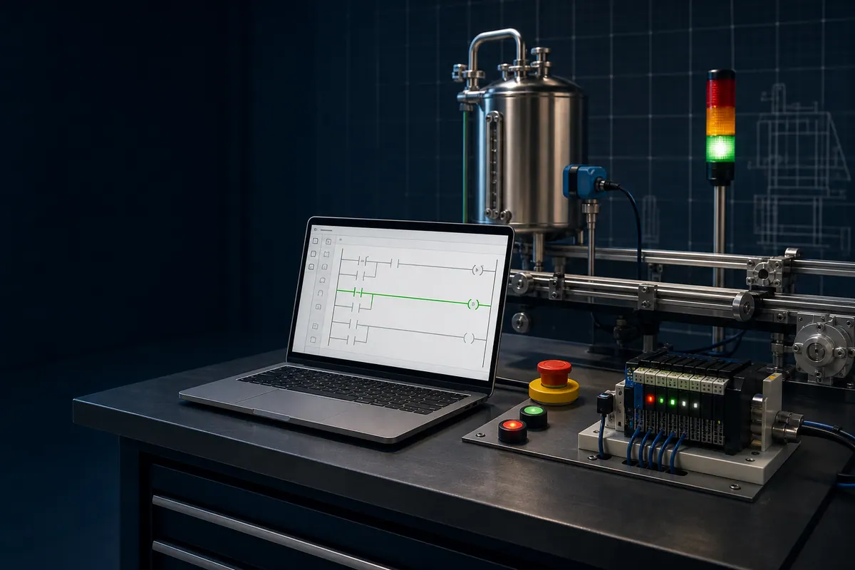
What Does a PLC Program Actually Do?
A PLC program is a set of rules that answer the question: "given the state of all my inputs, what should my outputs be right now?"
For example, a simple motor control program might say:
- If the Start button is pressed AND the Stop button is not pressed AND the motor is not already running, start the motor.
- If the Stop button is pressed, stop the motor.
- If the machine-safety system removes its healthy/permit signal, remove the ordinary run request and require a controlled recovery.
- If the motor is running for more than 5 minutes continuously, show a warning.
A standard PLC program can coordinate production behavior, but it is not a substitute for a risk assessment, safety-rated devices, verified wiring and validated safety logic.
Write an I/O contract before writing logic
Use names that describe meaning, not just terminal numbers. The example below deliberately distinguishes raw field state, normalized application state, command and feedback.
| Tag | Kind | TRUE means | Owner or source | Failure question |
|---|---|---|---|---|
| StartPB_Raw | physical input | start device's configured input state is active | I/O mapping layer | is the field contact and polarity documented? |
| StopHealthy_Raw | physical input | ordinary stop circuit is healthy | I/O mapping layer | does a broken wire produce the intended application state? |
| OverloadHealthy_Raw | physical input | motor overload auxiliary state is healthy | I/O mapping layer | is the contact current, latched or reset locally? |
| StartRequest | normalized input | application has a valid start request | input-normalization logic | was bounce or HMI arbitration handled? |
| StopHealthy | normalized permissive | ordinary run permission remains true | input-normalization logic | is this being mistaken for a safety channel? |
| MotorRunRequest | internal command | sequence requests the motor to run | motor-control routine | can exactly one routine write it? |
| MotorOutput | physical output | controller commands the starter or drive | output-mapping logic | are mode, inhibit and communication states visible? |
| MotorRunning | feedback input | independent feedback says the motor reached run state | starter, drive or process sensor | what timeout and disagreement alarm apply? |
The I/O contract is part of the program specification. Extend it with address, module/channel, electrical type, engineering unit, normal state, fail state, update rate and drawing reference when you move to real hardware.
The Scan Cycle
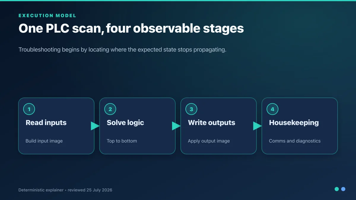
Every PLC follows the same basic loop:
- Read all inputs — sample every physical input and update the PLC memory.
- Execute the program — run through your logic, using the latest input values.
- Write all outputs — send the computed output states to physical outputs.
- Housekeeping — communications, diagnostics, internal maintenance.
This repeats continuously, but modern controllers can also run periodic and event tasks, asynchronous communications and independently updated remote I/O. Measure the actual task and signal path instead of relying on a generic millisecond range.
Understanding the scan cycle is the first mental model you need. Many beginner bugs come from misunderstanding when inputs are read, when outputs change, and what happens to timers during the scan.
Trace the first program scan by scan
Assume the logic retains a run request after a valid start, removes it when StopHealthy or OverloadHealthy becomes false, and checks independent running feedback. This teaching trace shows logical observations, not a guaranteed physical timing model.
| Observation | Start request | Stop healthy | Overload healthy | Prior run request | Calculated run request | Running feedback | Interpretation |
|---|---|---|---|---|---|---|---|
| 1 | FALSE | TRUE | TRUE | FALSE | FALSE | FALSE | idle and ready |
| 2 | TRUE | TRUE | TRUE | FALSE | TRUE | FALSE | start accepted; feedback can still be pending |
| 3 | FALSE | TRUE | TRUE | TRUE | TRUE | TRUE | request is sealed and device reports running |
| 4 | FALSE | TRUE | FALSE | TRUE | FALSE | TRUE | overload removes ordinary command; feedback may decay later |
| 5 | FALSE | TRUE | TRUE | FALSE | FALSE | FALSE | fault recovery does not silently restart |
| 6 | TRUE | FALSE | TRUE | FALSE | FALSE | stop dominates simultaneous start | |
| 7 | TRUE | TRUE | TRUE | FALSE | TRUE | a new valid start is accepted after recovery policy is satisfied |
This table exposes two states that a glowing coil can hide: the prior retained request used during calculation and the independent feedback observed from the device. When a real controller offers periodic/event tasks, immediate I/O, producer-consumer data or networked modules, capture the actual task and I/O timing too.
How PLC Programming Differs from Regular Programming
If you are coming from software development, several things will feel backwards:
1. Cyclic execution is common
Many PLC routines execute cyclically, so logic repeatedly evaluates current state. Modern controllers may also support periodic or event tasks. Learn the target scheduler and avoid assuming that every routine executes in one undifferentiated loop.
2. State lifetime must be explicit
PLC platforms provide local, program, controller, block-instance and global scopes in different forms. What matters is knowing which state persists between calls, which data is retained across restart, and which routine or block is allowed to write it.
3. Execution Time Is Bounded
A PLC task must finish within its configured timing budget. Unbounded loops, blocking designs and excessive work can delay other control behavior or trigger a watchdog. Use non-blocking state and timer patterns and measure worst-case execution on the target.
4. The Code Runs Forever
There is no "main is done, exit now." The PLC starts the program when it powers up and runs it until power is removed. Your code has to cope with being halfway through any operation when power cycles.
5. Safety Matters
Control software can affect physical equipment. Ordinary PLC logic must respect the approved safety design and must never bypass a safety function. Safety functions require the applicable lifecycle, suitable components, validated safety logic and documented tests.
The Current IEC 61131-3 Language Suite
IEC 61131-3:2025 Edition 4 covers three programming languages plus Sequential Function Chart elements. You will mainly encounter two or three:
- Ladder Logic (LD) — Visual language that looks like electrical relay diagrams. Most common starting point.
- Structured Text (ST) — Text-based, Pascal-like. Good for complex calculations.
- Function Block Diagram (FBD) — Graphical block-wiring. Good for control loops.
- Sequential Function Chart (SFC) — Step-by-step state machines. Good for sequences.
Legacy note: Instruction List (IL) was part of Edition 3 but was removed from the current Edition 4 suite. You may still encounter it in older projects.
Start with ladder logic. Once you are comfortable, add structured text for the things ladder handles poorly (math, loops, strings).
Your First Ladder Logic Rung
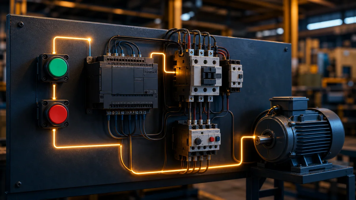
The simplest possible rung: a Start_Button contact on the left side of the rung, directly connected to a Motor coil on the right. When Start_Button is closed (pressed), the Motor coil energises. This is a momentary start — the motor runs only while the button is held.
Add a seal-in and a stop:
- A Start contact in series with a Stop (examine-on-normally-closed) contact drives the Motor coil.
- In parallel with the Start contact, add a Motor feedback contact.
Now: press Start, and the Motor energises. The Motor feedback contact closes, sealing the rung. The motor stays on even after Start is released. Press Stop, the series chain breaks, the Motor de-energises.
This is the three-wire motor control circuit, and it is the "hello world" of PLC programming. We cover it in depth in our motor start/stop tutorial.
Translate the requirement before drawing the rung
Write the ordinary-control requirement as a Boolean state update:
MotorRunRequest_next :=
    (StartRequest OR MotorRunRequest_previous)
    AND StopHealthy
    AND OverloadHealthy;
In Ladder Diagram, the start contact and prior run-request contact form a parallel branch; the stop and overload permissives remain in series; the result writes one internal run-request coil. Some platforms let a contact read the same Boolean tag written by the coil later in the rung or network, but evaluation, update and retentive behavior must be verified in the target documentation. An explicit state variable or motor Function Block can make ownership and testing clearer in larger projects.
Keep the layers separate:
| Layer | Example state | What it proves | What it does not prove |
|---|---|---|---|
| request | StartRequest | an operator or sequence asked to start | the command was accepted |
| permission | StopHealthy AND OverloadHealthy | ordinary run conditions currently allow a command | a safety function is valid or the mechanism is clear |
| command | MotorRunRequest / MotorOutput | software and output mapping request energization | starter, drive or motor moved |
| feedback | MotorRunning | independent configured evidence reports running | product flow or mechanical load is correct |
| process result | ConveyorSpeedOK or ProductDetected | the process response meets the requirement | every upstream component is healthy |
Before moving on, test at least these cases:
| Initial run state | Start | Stop requested | Overload fault | Expected run request |
|---|---|---|---|---|
| FALSE | FALSE | FALSE | FALSE | FALSE |
| FALSE | TRUE | FALSE | FALSE | TRUE |
| TRUE | FALSE | FALSE | FALSE | TRUE |
| TRUE | FALSE | TRUE | FALSE | FALSE |
| TRUE | FALSE | FALSE | TRUE | FALSE |
| FALSE | TRUE | TRUE | FALSE | FALSE |
Your first twelve-week practice milestones
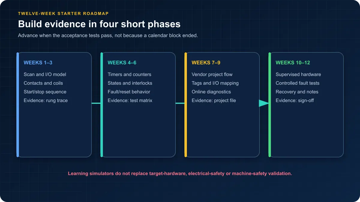
A calendar is not an acceptance test, so use the phases below as milestones rather than promises.
Weeks 1–3 — Concepts and first rung
- Understand the scan cycle.
- Learn the current IEC language suite and recognise legacy Instruction List.
- Read about ladder logic contacts, coils, and rungs.
- Build a mental model of PLC memory (inputs, outputs, internal bits, timers, counters).
Weeks 4–6 — Timers, counters and state
- Master contacts, coils, and branch logic (parallel rungs).
- Understand the seal-in pattern for motor control.
- Learn the standard timers (TON on-delay, TOF off-delay, TP pulse).
- Learn counters (CTU, CTD, CTUD).
Weeks 7–9 — Vendor project workflow
- Write a traffic-light sequence.
- Write a conveyor-with-photoeye sort.
- Understand set/reset coils.
- Learn how to track fault states and alarms.
Weeks 10–12 — Supervised transfer
- Build a batch-mixer or bottling-line scenario end to end.
- Add HMI-style status bits.
- Add fault handling.
- Review your code like an instructor would.
Use evidence gates instead of hours watched
| Gate | Deliverable | Minimum abnormal cases | Pass evidence |
|---|---|---|---|
| Boolean and scan model | start/stop truth table and scan trace | simultaneous start/stop; input transition between observations | prediction matches an observed trace |
| timer and counter state | timed motor-feedback fault and counted-parts exercise | timer reset; sensor stuck; counter reset; restart | expected/observed timing and count table |
| sequence | traffic light or conveyor state model | invalid transition; stopped sensor; timeout; reset | state diagram, transition table and trend/screenshot |
| project structure | exact vendor or IEC project manifest | uncalled routine; duplicate writer; wrong task assignment | cross-reference and execution-path review |
| diagnostics | one injected input, logic and output fault | stale input; lost feedback; inhibited output | fault found from evidence without random edits |
| supervised transfer | controlled bench procedure | power cycle; communications loss; safe stop; recovery | approved checklist, backup and as-left record |
Do not use the final row as a self-authorization to work on energized equipment. Employer procedures, competence requirements, arc-flash and electrical controls, machine risk assessment, safety validation and local law govern real work.
Practise logic in a simulator, then move into the approved vendor environment and supervised hardware when the project requires it. For guided practice, browse the ladder logic tutorial.
Choose tools by the next learning objective
You can learn the scan cycle, Boolean logic, timers and sequences without committing to an expensive vendor licence. Do not, however, treat a learning simulator as proof that native project files, firmware behavior, safety instructions, wiring or real I/O will behave identically.
| Objective | Appropriate starting tool |
|---|---|
| Learn Ladder, timers, counters and state | A browser or desktop learning simulator with observable I/O |
| Learn IEC POUs and task configuration | CODESYS Development System or OpenPLC, within their documented limits |
| Commission a named controller | The manufacturer-supported engineering tool and version for that controller |
| Learn physical I/O and diagnostics | A supervised, documented hardware bench with suitable protection |
| Validate a safety function | The approved safety lifecycle, hardware, toolchain and verification procedure |
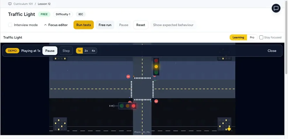
Disclosed browser practice option
PLC Simulation Software is operated by the same publisher as plcprogramming.io. It provides a non-expiring free account, 9 listed learning dialects and 170 source-catalogued practice records in the versioned product catalogue. Use it for repeatable logic exercises and simulated I/O—not as a production PLC or exact emulator of every vendor runtime.
How to troubleshoot your first PLC program
Do not begin by changing the rung that looks suspicious. First preserve the symptom: exact time, controller mode, active step, input/output indications, alarms and the action immediately before the failure. Then move through the signal path in one direction. Each observation should eliminate a layer.
- Confirm identity. Record controller family/catalogue, firmware, engineering-tool version, project name/revision and whether the online project matches the saved file.
- Confirm execution. Check controller mode, task state, scheduled program, main routine and calls. Logic that exists but is never invoked cannot control anything.
- Observe the raw input. Compare the physical device, module/channel diagnostics and raw tag. Do not force or jumper around a missing field signal.
- Observe normalization and permissives. Trace polarity, mode selection, interlocks and ordinary stop conditions.
- Cross-reference the command. Find every writer to the run request and output. A later assignment, HMI write, sequence routine or fault handler can overwrite the value you watched.
- Separate command from feedback. If the output command is true but feedback is false, move to module, network, starter/drive, field-circuit and mechanical evidence under the approved work procedure.
- Reproduce one controlled case. Record expected and observed states, fix only the supported cause, repeat the original case and run regression tests.
| Symptom | First software observation | Next boundary | Avoid this shortcut |
|---|---|---|---|
| input LED changes but application tag does not | raw channel, I/O mapping, normalization and update status | module configuration, wiring drawing and field device | changing addresses until one toggles |
| start is true but request stays false | stop/permissive chain, mode, task/call path and writer cross-reference | requirement and arbitration policy | bypassing the false permissive |
| request turns true then false in one cycle | duplicate writers, reset rung, sequence state and evaluation order | architecture/ownership review | adding a Set coil to “make it stick” |
| output command is true but module point is off | output mapping, inhibit/force state, controller mode and module diagnostics | rack/network/module configuration | assuming the final coil is the physical output |
| module point is on but motor does not run | independent feedback and drive/starter status available to the PLC | authorized electrical/mechanical diagnosis | forcing the output or defeating protection |
| motor runs but sequence does not advance | feedback qualification, sensor state, timer and current step | process/mechanical condition | manually writing the next state |
| timer never completes | instance invocation, enable continuity, preset/time base and reset path | task execution and platform timer semantics | increasing the preset without evidence |
| program works in simulation only | unsupported device/instruction behavior, startup state and I/O assumptions | version-matched vendor project and supervised bench | calling simulation a commissioning test |
A beginner's fault record
For every exercise, keep a short record with: requirement ID; project and tool version; initial state; injected condition; expected result; observed result; timestamp or scan trace; pass/fail; corrective action; and regression result. That record turns practice into evidence and makes an instructor's review much more useful than a screenshot of an energized coil.
Moving from generic basics to a vendor project
The scan, state and test concepts transfer; native projects do not. A CODESYS task calls Program POUs and CODESYS Function Block instances carry state. A Rockwell Logix task schedules programs containing routines and scoped tags. Siemens STEP 7 organizes OBs, FBs, FCs and DBs. Omron Sysmac uses Programs, Functions, Function Blocks, named variables, I/O Map assignments and tasks. Their similar IEC concepts do not guarantee identical file formats, instruction behavior, timer members, startup, retention, I/O refresh, online changes or safety support.
Before choosing a training path, write a platform manifest:
| Manifest field | Why a beginner needs it |
|---|---|
| controller family and exact catalogue | selects supported hardware, instructions and project type |
| firmware/runtime revision | constrains compatible engineering software and behavior |
| engineering tool and build | makes the project reproducible and identifies licence needs |
| language and task/routine/POU location | proves where and when the logic is intended to execute |
| I/O/module/network list | connects generic tags to real channels and update behavior |
| simulator or emulator boundary | states what was represented and what remained untested |
| startup, retention and power-cycle policy | prevents hidden assumptions about remembered state |
| backup, change and rollback record | supports controlled recovery if a transfer fails |
Choose the vendor environment that matches the controller you expect to encounter. Do not buy a course or licence merely because it says “IEC compliant.” Ask for the named tool release, supported target, executable labs, abnormal-case assessment, instructor feedback and evidence that the curriculum is still maintained.
Common Beginner Mistakes
- Watching tutorials without writing code. Video tutorials are passive. You learn by building, not by watching.
- Skipping the scan cycle. If you do not internalise how the scan works, you will write code that "works" in a tutorial and fails mysteriously on real hardware.
- Treating a program bit as a safety function. A simulated E-stop bit is useful for sequence testing but does not replace safety-rated devices, wiring, logic or validation.
- Hiding command priority. Test start and stop together and make the required dominant condition explicit.
- Confusing logical symbols with physical contacts. An examine-if-open instruction is not proof that the field contact is physically normally closed; document polarity and fail state separately.
- Not commenting code. Your future self in six months will thank you.
- Programming without paper. Sketch the logic on paper first. Draw the state machine. Draw the sequence. Then open the editor.
- Using output command as feedback. A true output tag says what software requested, not that the contactor, drive, motor or process responded.
- Leaving routine execution implicit. A routine can verify successfully while no scheduled task or call path invokes it.
- Editing before capturing evidence. An early write, force, power cycle or reset can destroy the condition that would have identified the actual cause.
Where to Go Next
After the first month, pick a direction:
- Want to ship real-world projects? Pick a vendor (Siemens, Rockwell, or Codesys), get certified, and start with maintenance or commissioning roles.
- Want depth on programming patterns? Work through all the standard scenarios (motor, traffic light, conveyor, elevator, batch mixer, PID temperature). Then add structured text.
- Want real-hardware experience? Set up a Raspberry Pi with OpenPLC. Connect some switches and LEDs. Write code that flashes them in real sequences.
- Want to understand industrial context? Read about the industries that use PLCs and the protocols that connect everything.
For certification and career paths, see our PLC career guide. For vendor-specific tutorials, browse the PLC guides section.
Conclusion
PLC programming can be entered through technician, electrician, engineering, software and apprenticeship routes. The qualification and supervised-experience requirements depend on the role, employer and jurisdiction. You do not need to buy a commercial licence before writing your first rung; you do need disciplined practice, clear test evidence and respect for the project’s safety and commissioning procedures.
Start with ladder logic. Build the motor-control seal-in rung, test the simultaneous-command and fault cases, then add a traffic-light sequence and conveyor photoeye. Progress when you can explain and reproduce the result—not when an arbitrary study period has elapsed.
Sources and scope
- IEC 61131-3:2025 Edition 4 publication record — current programmable-controller language-suite boundary and publication date.
- PLCopen IEC 61131-3 overview — industry context for the standard and programming model.
- PLCopen software-construction guidelines — naming, structure, coding and lifecycle guidance.
- CODESYS Development System — IEC application-development environment and editor context.
- CODESYS Task Configuration — task types, calls, interval, priority and watchdog configuration.
- Siemens STEP 7 V21: Programming a PLC — current Siemens block, tag and project workflow.
- Siemens S7-200 SMART system manual — one documented vendor example of process-image input, program and output-cycle behavior.
- Rockwell Logix 5000 Tasks, Programs, and Routines manual — task scheduling, program and routine execution.
- Rockwell Logix 5000 I/O and Tag Data manual — tags, I/O data and mapping context.
- Rockwell Logix 5000 programming-language guidance — current Logix language documentation.
- Omron Sysmac Studio Operation Manual W504 — I/O Map, POUs, tasks, simulation and online workflow for supported NJ/NX projects.
- Mitsubishi MELSEC iQ-R Programming Manual (Program Design) — another vendor-specific program, task and language implementation.
- OSHA control of hazardous energy — US workplace boundary for hazardous-energy control; use the applicable local law and site procedure.
Sources and product surfaces were checked on 30 August 2026. Examples on this page are original, vendor-neutral teaching patterns. Recreate and verify them in the engineering software, controller, firmware, I/O and safety architecture selected for the real project. The standards and vendor manuals define their own products and scopes; they do not validate this independent tutorial or the same-owner simulator offer.
Continue Learning
Start Here
Free Learning Resources
Frequently Asked Questions
How long does it take to learn PLC programming?
There is no reliable universal duration. Measure progress by tasks: explain the scan and I/O path, implement and test stop-dominant logic, use timers and counters correctly, diagnose a forced fault, archive a project, and transfer the result into a supported vendor environment. Professional commissioning competence also requires supervised field experience.
Do I need to buy a real PLC to learn?
Not for the first logic exercises. A simulator can teach state, timers, counters and testing without hardware. Use real hardware when you need to learn wiring, electrical diagnostics, communications, module configuration and commissioning, ideally on a supervised bench selected for the vendor ecosystem you intend to use.
What mathematics do I need to know?
For ladder logic: basic arithmetic and Boolean algebra. For PID loops: intuitive understanding of proportional/integral/derivative behaviour (the algebra is not complex). For advanced analog work: some linear systems and control theory helps but is not essential for most day-to-day work. Calculus is rarely required.
Can I learn PLC programming part-time while working another job?
Yes. Use a repeatable schedule built around completed exercises rather than hours watched: one requirement, one implementation, one abnormal-case table and one captured result per study block. Seek review from an instructor, experienced controls professional or technically focused community before treating a project as portfolio evidence.
What is the scan cycle and why does it matter?
The scan cycle is the useful model of reading inputs, executing scheduled logic, updating outputs and performing system work. Modern controllers may also use periodic and event tasks, asynchronous communications, remote-I/O intervals and immediate-I/O instructions. It matters because task and signal timing determine whether a transition is seen and when an output can respond.
What is the first project I should build after learning the basics?
Build a motor start/stop request with a seal-in path, stop-dominant behavior, overload permissive and feedback timeout. Treat any E-stop input as a simulated status only, not a real safety function. Test simultaneous start/stop, loss of permissive, missing feedback, reset and restart before moving to a traffic-light or conveyor sequence.
What is the best PLC programming language for a beginner?
Ladder Diagram is a practical first language for discrete machine logic because contacts, branches and coils make Boolean decisions visible to many maintenance teams. Then learn Structured Text for calculations, arrays, loops and data handling. The current IEC 61131-3:2025 suite also includes Function Block Diagram and SFC structuring elements, but exact language support depends on the controller and tool.
What is the difference between a PLC input and output?
An input is a controller value obtained from a switch, sensor, drive, network device or other source. An output is a command sent toward an actuator, lamp, valve, contactor or drive. A true output command does not prove the device responded, so real programs keep command and independent feedback separate.
Is PLC programming hard to learn?
The first Boolean and ladder exercises are approachable, but professional competence includes electrical drawings, controller scheduling, data, networks, diagnostics, safety boundaries, version control and controlled commissioning. Treat learning as a sequence of observable tasks and abnormal-case tests rather than a promise based on hours watched.
Can I learn PLC programming without an electrical or engineering degree?
You can learn the programming model and build tested simulated exercises without a degree. Job eligibility and authority to work on industrial equipment depend on the role, employer, jurisdiction, qualifications and supervised experience. Programming knowledge does not replace electrical competence, machinery-risk controls or authorization for hazardous work.