Water Treatment PLC Programming: Pumps & Dosing
Build safer water-treatment PLC logic for pump sequencing and chemical dosing with permissives, manual/auto states, failure tests and EPA guidance.
Water-treatment PLC logic should make every pump and chemical-feed command traceable to a valid mode, approved setpoint, healthy instrument, confirmed process flow and defined fault response. The examples on this page are training templates; none of their doses, alarm limits, timers or equipment selections is approved for a real utility.
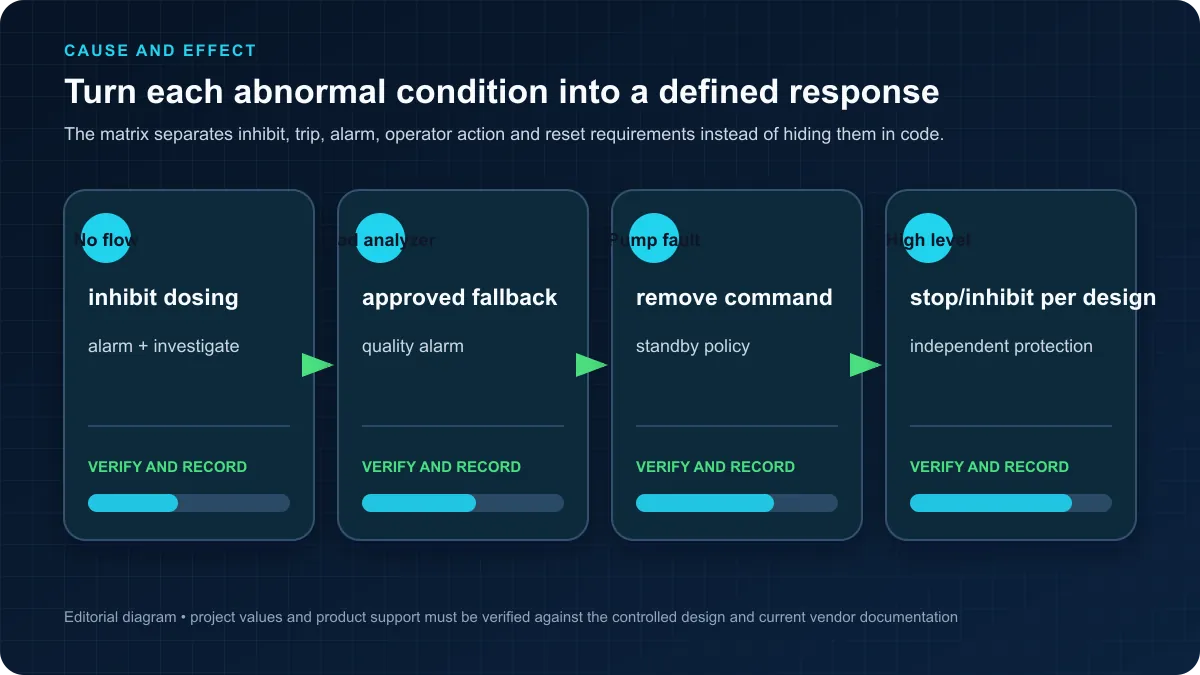
For a pump, prove stop dominance, dry-run/low-suction protection, feedback timeout, duty/standby behavior and restart after power or communications loss. For chemical feed, prove no-flow shutdown, instrument bad-quality handling, bounded operator setpoints, independent high-limit protection where required, and a safe recovery sequence.
Minimum pump and dosing test matrix
| Test | Deliberate condition | Expected control response |
|---|---|---|
| Valid pump start | Auto demand, suction/process permissives valid | Selected available pump starts; feedback arrives before timeout |
| Failed start | Command on, no running feedback | Command removed or fallback applied per design; fault identifies the failed unit |
| Low suction/dry run | Protective condition becomes false | Pump response follows approved equipment/process protection |
| No-flow dosing | Water flow below validated minimum | Chemical command off; no stale PID output retained as an active command |
| Analyzer bad quality | Residual/pH signal invalid or stale | Feedback trim disabled or process moved to the approved fallback state |
| Excess command | Operator/HMI requests above approved maximum | Request rejected or clamped with alarm and audit event |
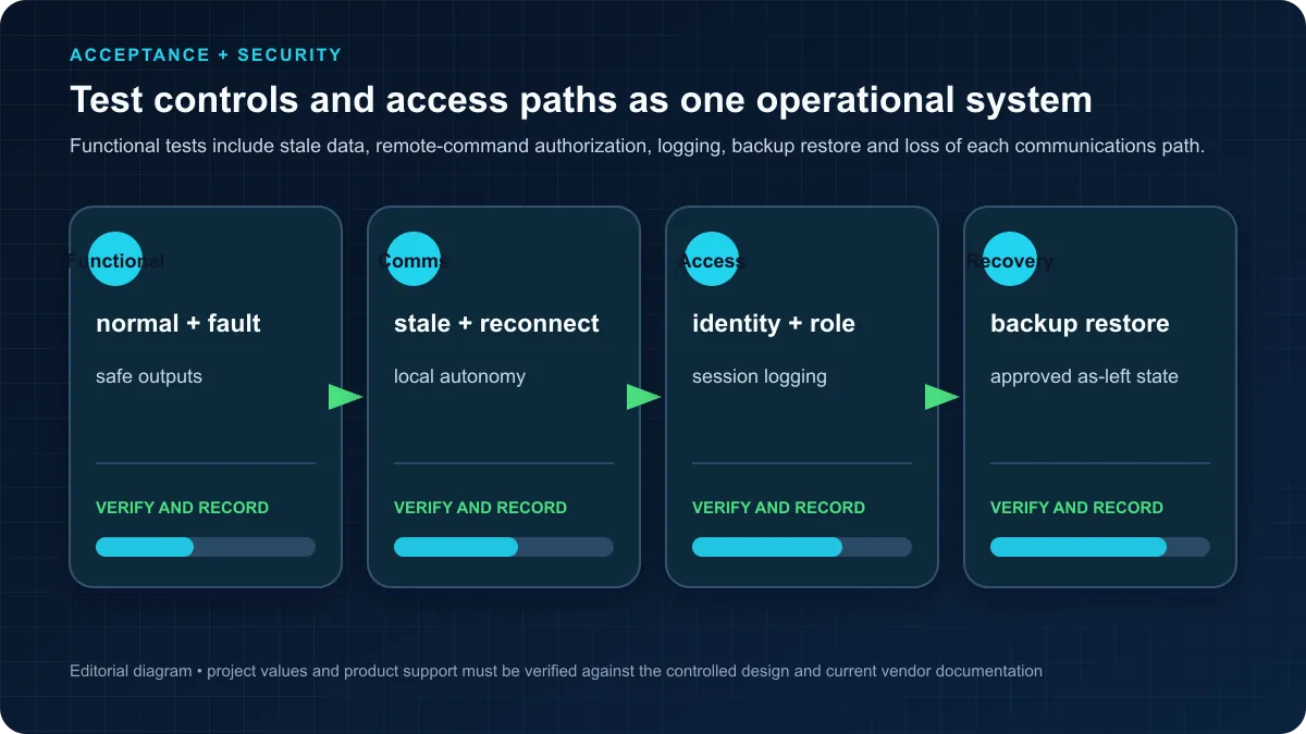
| Communications loss | SCADA or remote-link failure | Local control holds or moves to the documented state; remote writes rejected |
| Power recovery | PLC and I/O restart | No unintended pump or feeder restart; operator recovery state is explicit |
Practice the pump/dosing state logic in the browser before mapping it to site I/O. The simulator cannot establish treatment efficacy, regulatory compliance, chemical safety or real equipment protection.
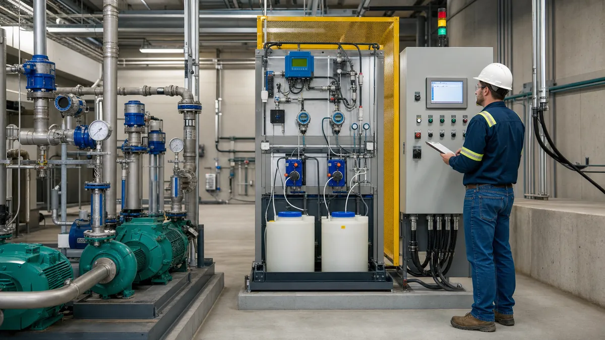
Table of Contents
- Water Treatment Process Overview
- PLC Hardware Selection for Water Treatment
- Control System Architecture
- Programming Water Level Control
- Chemical Dosing Control Systems
- Pump Control and VFD Integration
- Complete Water Treatment Plant Example
- Best Practices for Water Treatment PLCs
- Frequently Asked Questions
Water Treatment Process Overview
The descriptions below are control-system context, not a treatment-design specification. Permits, approved treatment studies, process calculations, equipment manuals and operator authority define chemical selection, dose, contact time, sampling and protective actions.
Raw Water Intake and Screening Systems
The water treatment process begins with raw water intake from surface water sources (rivers, lakes, reservoirs) or groundwater wells. Intake systems require PLC control for intake gate positioning, screen cleaning cycles, and low water level protection to prevent damage to downstream equipment while ensuring continuous water supply during varying source water conditions.
Screen cleaning automation prevents debris accumulation that can restrict flow and damage pumps. PLC programming coordinates automatic cleaning cycles based on differential pressure measurements, timer intervals, or operator commands while interlocking screen operation with intake pumps to prevent system damage during cleaning operations.
Intake pump control must maintain consistent flow to downstream processes while responding to changing source water levels, treatment plant demand, and equipment availability. Programming typically includes multiple pump sequencing with lead/lag rotation, variable frequency drive control for flow regulation, and protection interlocks for low suction pressure or high discharge pressure conditions.
Pre-treatment processes such as pre-chlorination or pre-oxidation may occur at the intake to control biological growth, improve downstream treatment effectiveness, and reduce taste and odor compounds. These systems require coordinated control between chemical feed systems and intake flow rates to maintain proper dosing ratios.
Coagulation and Flocculation Processes
Coagulation may use an approved chemical and process design to destabilize suspended particles before separation. PLC logic can implement the approved flow-paced demand, limits, permissives, analyzer-validity handling and operator modes; it cannot determine treatment chemistry or prove treatment effectiveness.
Rapid mixing immediately follows coagulant addition to ensure uniform chemical distribution throughout the water flow. Control programming manages mixer motor operation, speed control for variable speed mixers, and power monitoring to detect mixer problems that could compromise treatment effectiveness.
Flocculation provides gentle mixing to promote particle aggregation into larger floc particles that settle more effectively. Multi-stage flocculation systems require coordinated control of multiple mixers operating at progressively slower speeds, with programming that adjusts mixing intensity based on water quality, temperature, and coagulant type.
Jar tests and online instruments may inform operator or control decisions where the utility has validated that method. Any automated trim must define analyzer quality, allowable range, rate limits, fallback, independent protections and operator authority in the approved process design.
Sedimentation and Clarification
Sedimentation basins allow flocculated particles to settle under gravity, removing the majority of suspended solids before filtration. PLC control manages sludge removal systems, basin water level control, and flow distribution to multiple basins to optimize settling efficiency and prevent solids carryover to filters.
Automated sludge collection and removal prevents solids accumulation that reduces basin effectiveness. Programming coordinates collector drive operation, sludge pumping cycles, and waste discharge based on settled solids depth measurements, timer schedules, or operator inputs while monitoring equipment for mechanical problems.
Plate settlers and tube settlers increase effective settling area within existing basin volumes. Control systems manage hydraulic loading rates and cleaning cycles to maintain settler effectiveness while preventing solids accumulation and short-circuiting flow patterns that reduce treatment efficiency.
Dissolved air flotation (DAF) systems provide alternative clarification for water with low-density particles or algae. PLC programming coordinates air saturation, recycle pump operation, chemical addition, and float skimming systems to optimize particle removal while managing the increased complexity compared to conventional sedimentation.
Filtration Systems
Filtration removes remaining suspended particles after sedimentation, typically using rapid sand filters, dual-media filters, or membrane filtration systems. PLC control manages filter operation, backwashing cycles, and performance monitoring to maintain consistent filtered water quality while optimizing filter run times and backwash water consumption.
Filter influent valve control regulates flow to individual filters, ensuring equal loading across multiple filters while preventing excessive flow rates that compromise filtration effectiveness. Programming includes flow pacing algorithms, level control strategies, and filter availability logic that distributes flow only to operational filters.
Backwash automation determines when filters require cleaning based on head loss development, runtime duration, or water quality measurements. Automated backwash sequences control multiple valves, pumps, and air scour systems following precise timing sequences that ensure effective cleaning while preventing filter media loss or equipment damage.
Membrane filtration systems (microfiltration, ultrafiltration) require sophisticated control programming for filtration cycles, backwash sequences, chemical cleaning cycles, and integrity testing. These systems demand precise control timing, flow measurement, pressure monitoring, and automated recovery from membrane fouling or system upsets.
Disinfection and pH Adjustment
Chlorination systems provide primary disinfection and maintain residual chlorine throughout the distribution system to prevent bacterial regrowth. PLC programming controls chemical feed pumps, monitors residual chlorine levels, and implements compound loop control that adjusts dosing based on both flow rate and residual chlorine measurements to maintain target residual levels.
Ultraviolet (UV) disinfection systems provide chemical-free disinfection for systems requiring higher treatment standards or avoiding disinfection byproducts. Control programming monitors UV intensity, lamp status, flow rate, and UV transmittance to ensure adequate disinfection dose while managing lamp operation and cleaning cycles.
pH adjustment systems add caustic soda, lime, or carbon dioxide to adjust treated water pH for corrosion control and regulatory compliance. PID control algorithms maintain target pH setpoints while compensating for alkalinity variations, temperature effects, and system residence time delays that complicate pH control.
Fluoridation systems add fluoride compounds to prevent dental decay in communities with water fluoridation programs. Precision dosing control with flow pacing, residual monitoring, and safety interlocks ensures proper fluoride levels while preventing over-feeding that could violate maximum contaminant levels.
Distribution System Control and Monitoring
High service pumps deliver treated water to the distribution system, maintaining pressure and flow to meet customer demands. Control systems manage multiple pump combinations with variable frequency drives, optimizing energy consumption while maintaining pressure setpoints and providing adequate fire flow capacity during emergencies.
Storage tank level control balances water production with system demand, using tank levels to modulate treatment plant production rates. Programming coordinates treatment processes with storage levels, providing stable operation while maintaining adequate reserves for peak demands and emergency situations.
Pressure zone control manages pump operation and pressure reducing valves to maintain appropriate pressures in systems with varying elevations or pressure requirements. Automated control prevents excessive pressures that waste energy and stress piping while ensuring adequate pressure for all system customers.
SCADA telemetry systems monitor remote facilities including booster stations, storage tanks, and distribution system pressure/flow points. Programming integrates remote data acquisition with central control algorithms, providing operators with comprehensive system visibility while enabling automated responses to distribution system conditions.
PLC Hardware Selection for Water Treatment
Environmental Protection Requirements
Water facilities can expose equipment to humidity, washdown, flooding, corrosive chemicals and temperature extremes. Select enclosure material, ingress/corrosion rating, ventilation and hazardous-location classification from the actual area assessment and chemical compatibility data; “NEMA 4X” alone does not specify stainless steel or solve every chemical exposure.
Select the exact PLC and I/O part numbers from the required environmental ratings, lifecycle, communications, redundancy, cybersecurity support, memory, task load and local service capability. A controller family name is not evidence that a specific model suits the installation.
Temperature extremancy in outdoor installations or unheated buildings may require heated enclosures or PLCs rated for extended temperature ranges. Chemical feed buildings and chlorine rooms require special attention to corrosion protection and adequate ventilation to prevent equipment damage from chemical vapors.
Proper enclosure design with appropriate environmental ratings, ventilation, heating/cooling, and humidity control protects PLC hardware while extending equipment life and reducing maintenance requirements. Following NEMA and IP rating standards ensures adequate protection for specific installation conditions.
I/O Requirements and Expansion
Build the I/O count from approved P&IDs, motor/valve lists, analyzer packages and cause-and-effect requirements. Add documented spare capacity based on the project's expansion plan, enclosure space, power and network budget rather than a universal percentage.
Analog inputs monitor critical process variables including flow rates (4-20mA from magnetic flowmeters), pressures (4-20mA from pressure transmitters), levels (4-20mA from ultrasonic or pressure level transmitters), water quality parameters (pH, turbidity, chlorine residual, dissolved oxygen), and equipment performance indicators (motor current, valve position, VFD feedback).
Digital inputs detect equipment status (pump running, valve positions, motor overloads, alarm contacts), process conditions (high/low level switches, flow switches, pressure switches), and operator interface devices (pushbuttons, selector switches, emergency stops). Proper input filtering and isolation prevents false triggering from electrical noise common in treatment plants.
Digital outputs control process equipment including pumps, valves, chemical feeders, and indication lights. Relay outputs provide isolation for motor starters and high-voltage devices, while transistor outputs suit pilot duty applications such as solenoid valves and indicator lights. Proper output sizing and protection prevents overload and ensures reliable operation.
Communication Capabilities
Modern water treatment control systems require robust networking capabilities for SCADA integration, remote access, equipment integration, and regulatory reporting. Industrial Ethernet protocols including Modbus TCP/IP, EtherNet/IP, and PROFINET provide standard communication platforms supported across equipment manufacturers.
SCADA may use OPC UA, Modbus TCP or another supported interface. Define read/write ownership, update requirements, stale-data detection, time synchronisation, authentication and loss-of-communications behavior for each data class.
Variable frequency drive integration usually employs manufacturer-specific networks (DeviceNet, PROFIBUS, EtherNet/IP) or Modbus RTU/TCP for parameter access, speed control, and status monitoring. Proper network configuration and programming provides seamless VFD integration with automatic fault detection and coordinated control.
Remote access is a high-risk capability, not a default feature. Require asset-owner approval, strong identity controls, least privilege, managed access paths, logging, session limits and an incident-response/offboarding process consistent with current EPA/CISA guidance.
Redundancy for Critical Processes
Critical processes may justify redundant controllers, networks, power or instruments, but redundancy introduces common-cause, maintenance and switchover risks. Specify the tolerated interruption and state transfer, then fault-test the exact redundant architecture.
Cost-benefit analysis must consider process criticality, consequences of control system failure, alternative backup strategies, and budget constraints when evaluating redundancy requirements. Many water systems implement partial redundancy for most critical controls (disinfection, high service pumping) while accepting brief outages for less critical processes.
Redundant communication networks prevent single-point failures in SCADA systems serving multiple remote facilities. Ring or star network topologies with automatic failover ensure continued communication even during network cable damage or switch failures that could otherwise isolate remote sites.
Size UPS capacity from measured load, required ride-through or shutdown time, battery ageing, environment and generator transfer behavior. Include alarm, bypass, maintenance and periodic load-test requirements; do not copy a generic runtime.
Control System Architecture
Distributed vs Centralized Control Strategies
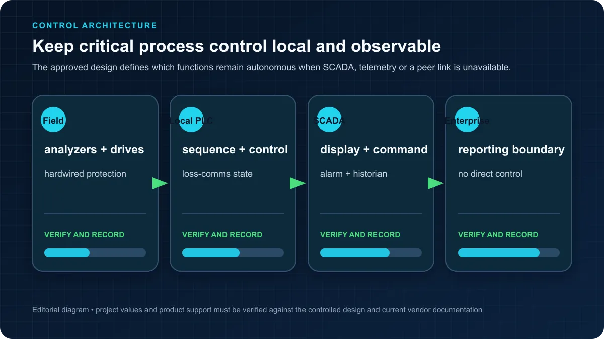
Water utilities use centralized, distributed and hybrid architectures. Select the topology from process criticality, tolerated interruption, environmental conditions, cable/network constraints, cybersecurity zones, maintenance capability and tested loss-of-communications behavior; no topology is universally more reliable or cheaper.
Process-level PLCs (treatment plant, pump stations, storage facilities) implement all automatic control sequences locally, continuing operation during SCADA communication failures while logging alarms and trend data for upload when communication restores. This architecture ensures critical processes continue operating even during central system problems.
Central SCADA systems provide operator interface, data logging, reporting, and coordination between multiple facilities. Operators monitor and control distributed processes from central locations while SCADA systems aggregate data for performance analysis, regulatory reporting, and management dashboards.
Peer-to-peer communication between process PLCs enables direct coordination without SCADA involvement. For example, treatment plant production rates can directly respond to distribution system storage levels, providing stable control without central system dependencies that could compromise reliability.
SCADA System Integration Architecture
SCADA integration requires careful attention to data organization, communication efficiency, and alarm management to prevent operator information overload while ensuring critical information visibility. Tag naming conventions, screen hierarchies, and alarm priorities must follow consistent standards that operators understand and trust.
Real-time data exchange focuses on current process values, equipment status, and active alarms requiring operator attention. Historical data collection captures trend information, production totals, and alarm archives for analysis and reporting without overwhelming real-time communication networks.
Operator control capabilities through SCADA must include appropriate permissive logic and safety interlocks preventing dangerous operations. Programming should verify that remote commands are safe for current process conditions before execution, providing feedback when commands cannot be executed safely.
Automatic event logging documents all operator commands, alarm occurrences, equipment starts/stops, and process excursions creating audit trails for regulatory compliance and incident investigation. Log design must balance comprehensive documentation with database size management and query performance requirements.
HMI Requirements for Plant Operators
Operator interface design critically impacts plant performance, with well-designed HMI screens improving operator effectiveness while poor designs increase errors and slow response to problems. Following HMI design best practices and ISA-101 standards creates intuitive interfaces that operators trust and use effectively.
Overview screens provide at-a-glance process status with clear indication of normal operation, active alarms, and equipment out of service. Operators should immediately recognize abnormal conditions without reading text or interpreting complex graphics that slow recognition and response.
Detail screens for process areas provide access to setpoints, control modes, equipment commands, and detailed status information. Clear organization with consistent layouts across similar processes reduces operator learning curves while improving navigation and reducing errors.
Trend displays show process performance over time, helping operators understand process dynamics, troubleshoot problems, and optimize performance. Multiple time ranges (current shift, past 24 hours, week, month) serve different operational needs from immediate troubleshooting to longer-term performance analysis.
Remote Monitoring and Telemetry Systems
Remote site monitoring enables small water systems to operate multiple facilities without operators at each location. Telemetry systems using cellular, radio, or fiber communications connect remote sites to central SCADA systems, providing continuous monitoring and control with automated alarm notification to on-call personnel.
Alarm delivery to operator phones via text messages or automated calls ensures rapid response to critical alarms during off-hours. Programming must implement alarm acknowledgment tracking, escalation procedures for unacknowledged alarms, and suppression of nuisance alarms that erode operator confidence in alarm systems.
Data logging at remote sites preserves information during communication outages, uploading stored data when communication restores. Local control programming continues automatic operation during communication failures, preventing process upsets and maintaining treatment quality without continuous SCADA connectivity.
Cybersecurity for remote access demands careful implementation following water sector cybersecurity guidelines and EPA recommendations. Firewalls, VPNs, authentication, and access logging protect systems from cyber threats while enabling necessary remote operational support and emergency response capabilities.
Programming Water Level Control
Tank Level Measurement Technologies
Ultrasonic level transmitters provide non-contact level measurement suitable for most water applications, mounting above maximum liquid level and measuring distance to the water surface using ultrasonic pulses. PLC programming must account for measurement delays, occasional signal loss during foam or turbulence, and temperature compensation requirements.
Submersible pressure transmitters measure level based on hydrostatic pressure, providing reliable measurement immune to foam, turbulence, or surface conditions affecting ultrasonic sensors. Programming converts pressure readings to level using specific gravity compensation and transmitter mounting elevation, with proper zero adjustment during installation.
Float switches provide simple high/low level indication for backup protection and critical alarms. Programming typically uses float switches as independent safety interlocks separate from primary level control, preventing overflow or pump damage during transmitter failures or control system problems.
Radar, ultrasonic, hydrostatic and other level technologies have different installation and failure modes. Select from the actual vessel geometry, foam/turbulence, vapor, dielectric properties, mounting, maintenance, environmental rating and vendor application data, then test the signal under representative conditions.
PID Control for Level Regulation
PID (Proportional-Integral-Derivative) control provides stable tank level regulation by modulating inlet flow, outlet flow, or pump speed to maintain target setpoints. Proper PID tuning balances responsive control with stability, avoiding oscillations that waste energy and stress equipment while maintaining levels within acceptable ranges.
Level-loop dynamics depend on tank geometry, inflow/outflow relationship, pump curves and disturbances. Identify the controller algorithm and units, measure the response, and tune within approved output/rate limits; do not copy generic gains or integral times.
Anti-reset windup protection prevents integral term accumulation when control output reaches limits (0% or 100%), avoiding excessive overshoot when conditions change. Programming should freeze integral accumulation or implement conditional integration that only accumulates when control output is not saturated.
Cascade control strategies use level controller output as setpoint for flow controllers, improving disturbance rejection and response speed. The outer level loop provides slow, stable control while inner flow loops provide fast, accurate flow control to achieve level controller demands.
Complete Ladder Logic Example: Clearwell Level Control
// Platform-neutral clearwell control skeleton.
// All scale, tuning, level and speed values come from ApprovedConfig.

LevelValid := LevelQualityGood AND NOT LevelStale;
Pump1Available := Pump1Ready AND NOT Pump1Fault AND NOT Pump1Maintenance;
Pump2Available := Pump2Ready AND NOT Pump2Fault AND NOT Pump2Maintenance;

IF NOT LevelValid THEN
    CALL ApplyApprovedLevelSignalFailureResponse();
    LevelControlFaultLatched := TRUE;
ELSE
    Demand := BoundedLevelController(
        Setpoint := ApprovedConfig.LevelSetpoint,
        PV := MeasuredLevel,
        Limits := ApprovedConfig.ControllerLimits
    );

    LeadPump := SelectAvailableLead(
        Pump1Available,
        Pump2Available,
        RuntimeAndStartData
    );

    CALL StagePumps(
        Demand := Demand,
        Lead := LeadPump,
        Config := ApprovedConfig.PumpStaging,
        StartCommands => PumpStartCommands,
        SpeedCommands => PumpSpeedCommands
    );
END_IF;

// Independent protection/status inputs override ordinary commands
// only according to the approved cause-and-effect matrix.
CALL ApplyCauseAndEffect(
    HighLevelProtection,
    LowLevelProtection,
    SuctionProtection,
    DischargeProtection,
    Commands := PumpStartCommands
);

CALL VerifyPumpFeedback(
    Commands := PumpStartCommands,
    RunningFeedback := PumpRunningFeedback,
    Timeouts := ApprovedConfig.FeedbackTimeouts
);
Lead/Lag Pump Sequencing Logic
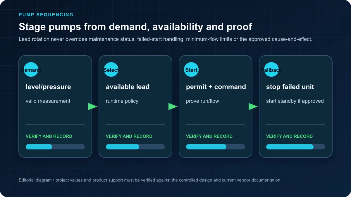
Pump alternation strategies distribute operating hours evenly across multiple pumps, preventing premature wear on a single unit while maintaining backup capacity. Programming tracks runtime hours for each pump, automatically rotating lead pump assignment daily, weekly, or after specified runtime thresholds.
Automatic lead/lag logic should enforce the approved start spacing, minimum run/off times and available electrical/hydraulic capacity. The values come from the pump, drive, process and power-system design.
Equal wear algorithms compare cumulative runtime hours, automatically selecting the pump with lowest total hours as lead pump. This strategy works well for systems with uniform pump sizing where equal runtime distribution is the primary objective regardless of efficiency considerations.
Efficiency-based sequencing uses pump performance curves and system operating points to select the most efficient pump combination for current demand. More sophisticated than simple runtime equalization, this approach reduces energy consumption while maintaining adequate runtime distribution to prevent equipment deterioration from extended idle periods.
Overflow and Low Level Protection
Independent level switches may provide a separate protection layer when required by the hazard/operability analysis. Their wiring, voting, proof-test interval and response must be defined in the cause-and-effect specification.
Do not universally start every pump at maximum speed on high level; that can exceed downstream capacity, dead-head equipment or worsen a release. Execute the approved cause-and-effect action for the specific tank and hydraulic system, and alarm with the site-defined escalation.
For low level, apply the equipment/process protection defined for the exact pump and suction arrangement. Whether it stops immediately, transfers duty or requires manual reset is project-specific.
Redundant protection using both analog transmitter levels and independent float switches provides defense-in-depth against single-point failures. Programming should alarm when transmitter and float switch readings disagree significantly, indicating likely measurement problem requiring investigation before failure causes process upset.
Chemical Dosing Control Systems
Chlorine Dosing Proportional to Flow
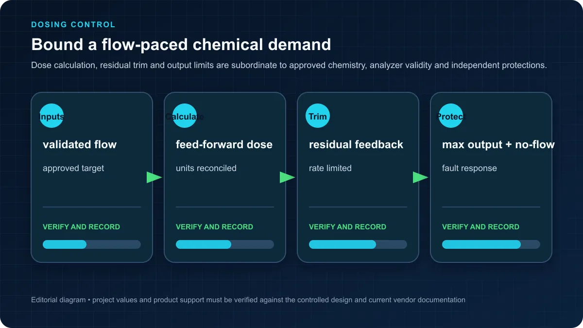
Flow-paced chlorine dosing maintains consistent chlorine residual by adjusting chemical feed rate proportional to water flow, compensating for varying treatment rates throughout the day. Basic flow pacing calculates chemical demand as simple ratio of flow rate multiplied by target dose (mg/L), providing predictable dosing without residual feedback.
Compound loop control improves on simple flow pacing by incorporating residual chlorine measurements, adjusting base dosing calculation to maintain target residual despite variations in chlorine demand from changing water quality or temperature. This "trim" adjustment prevents under-dosing during high demand periods while avoiding over-dosing waste during low demand conditions.
Feed-forward control uses raw water quality measurements (TOC, ammonia, turbidity) to anticipate chlorine demand changes before they affect residual, providing proactive adjustment that maintains more stable residual control than reactive-only feedback systems.
Dosing pump control interfaces vary by chemical feeder type - diaphragm metering pumps typically use 4-20mA stroke length adjustment signals, peristaltic pumps use 4-20mA speed control, and gas chlorinators use vacuum control signals. Programming must scale PID controller outputs to appropriate signal ranges for specific feeder equipment.
pH Control with Acid/Base Dosing
pH control presents significant challenges due to highly nonlinear titration curves, process deadtime, and strong disturbance effects from water chemistry variations. Successful pH control programming requires understanding these characteristics and implementing appropriate compensation strategies beyond simple PID control.
Gain scheduling adjusts PID parameters based on current pH value, applying higher gain when operating on flat portions of the titration curve (far from target pH) and lower gain near setpoint where small chemical additions cause large pH changes. This adaptation prevents oscillations while maintaining reasonable response speed.
Deadtime compensation accounts for delays between chemical injection points and pH measurement locations. Feed-forward trim based on flow rate changes helps compensate for residence time variations, while adaptive deadtime estimation can improve controller performance across varying operating conditions.
Cascade control with chemical flow loops inside pH control loops provides improved disturbance rejection and more predictable control. The outer pH loop outputs chemical flow demand to inner flow controllers that precisely meter chemical addition, isolating pH control from chemical pump nonlinearities and pressure variations affecting chemical delivery.
Coagulant Dosing Systems
Coagulant dosing control must respond to raw water quality variations while maintaining proper coagulant-to-water ratios across varying treatment rates. Streaming current detectors (SCD) provide real-time measurement of coagulant effectiveness, enabling automated dose optimization that adjusts for changing raw water characteristics.
Jar testing results establish baseline coagulant doses for typical water conditions. Programming stores seasonal dose profiles or water quality correlation equations that estimate required doses based on turbidity, color, alkalinity, or other readily measured parameters when streaming current monitoring is not available.
Multiple coagulant feed points in large plants require coordinated control ensuring proportional distribution to all injection points. Programming should monitor individual feeder operation, automatically redistributing flow if feeders fail while alarming operators to equipment problems requiring attention.
Chemical inventory management tracks consumption rates, calculates days of supply remaining, and alerts operators when reordering is needed. Integration with chemical tank level monitoring provides accurate inventory information while trending consumption patterns helps optimize chemical purchasing and storage requirements.
PID Tuning for Chemical Control Loops
Chemical control loops generally require conservative tuning with emphasis on stability over fast response. Excessive aggressiveness causes oscillations that waste chemicals, vary residual levels, and frustrate operators who may switch to manual mode rather than trust unstable automatic control.
Choose a tuning method from the approved process-control design, using a bounded test with operators and treatment/process specialists present. Record process dead time, analyzer sample/transport delay, output limits, anti-windup behavior and response across expected flow and water-quality conditions.
Do not copy generic gain or integral-time ranges. Chemical concentration, mixing, injection location, analyzer dynamics and process residence time can make superficially similar loops behave very differently. Decide whether PI, PID, feed-forward plus trim, model-based control or manual/operator-supervised control is appropriate from the validated process study.
Safety Interlocks and Alarms
Chemical safety interlocks prevent hazardous conditions including excessive doses that could violate water quality standards, equipment failures that could cause uncontrolled chemical releases, and unsafe conditions for operators or downstream processes.
Approved high/low bounds should be configured from process-design and regulatory requirements, protected by role-based access and checked at every command path. The required shutdown, hold-last, fallback or operator action depends on the chemical and treatment process.
Low-supply alarms should use validated level/consumption calculations and a site-defined response time. Redundant feed systems require proof that changeover cannot cross-connect incompatible chemicals, introduce air or create an unverified dose.
Containment monitoring for chemical storage and feed areas detects leaks or spills, triggering alarms and potentially shutting down chemical feed equipment to minimize release quantities. Gas chlorine installations require additional safety systems including leak detection, ventilation control, and emergency scrubber activation.
Safe training skeleton for a chemical-feed command
The skeleton below deliberately omits real dose calculations and limits. Those values must come from an approved process specification and independently reviewed unit conversion. ApprovedDemand represents the reviewed calculation, not an HMI field.
// Platform-neutral structured-text pseudocode.
// No real chemical, setpoint, unit conversion or safety limit is supplied.

FlowValid       := FlowQualityGood AND NOT FlowStale;
AnalyzerValid   := AnalyzerQualityGood AND NOT AnalyzerStale;
EquipmentReady  := FeedPumpReady AND SupplyAvailable AND ContainmentHealthy;
ModePermitsFeed := AutoMode AND PlantTreatmentEnabled AND ApprovedRecipeLoaded;

NoFlowTrip      := NOT FlowValid OR (MeasuredFlow < ApprovedConfig.MinimumFeedFlow);
HighLimitTrip   := IndependentHighLimitActive;
FeedPermissive  := ModePermitsFeed AND EquipmentReady
                   AND NOT NoFlowTrip AND NOT HighLimitTrip;

IF AnalyzerValid AND FeedbackTrimEnabled THEN
    BoundedTrim := LIMIT(
        ApprovedConfig.TrimLow,
        ReviewedFeedbackController.Output,
        ApprovedConfig.TrimHigh
    );
ELSE
    BoundedTrim := ApprovedConfig.AnalyzerFaultTrim;
END_IF;

RequestedCommand := ReviewedDoseCalculation(
    Flow := MeasuredFlow,
    ApprovedRecipe := ApprovedConfig,
    Trim := BoundedTrim
);

CommandInRange := (RequestedCommand >= ApprovedConfig.CommandLow)
                  AND (RequestedCommand <= ApprovedConfig.CommandHigh);

FeedPumpStart := FeedPermissive AND CommandInRange;
FeedCommand   := SEL(FeedPumpStart, ApprovedConfig.SafeOutput, RequestedCommand);

IF NOT FeedPermissive OR NOT CommandInRange THEN
    FeedPumpStart := FALSE;
    FeedCommand := ApprovedConfig.SafeOutput;
    FeedFaultLatched := TRUE;
END_IF;

// Separate logic verifies running feedback, actual chemical flow,
// command-versus-delivery deviation, reset authority and audit logging.
Pump Control and VFD Integration
Variable Frequency Drive Control Fundamentals
Variable frequency drives (VFDs) provide energy-efficient pump control by varying motor speed to match system demands rather than throttling discharge valves or cycling pumps on/off. PLC integration with VFDs requires understanding communication protocols, control modes, parameter access, and fault handling to create reliable integrated systems.
Communication methods include hardwired analog signals (4-20mA, 0-10VDC), digital I/O for basic control, or network communications (Modbus RTU, EtherNet/IP, PROFIBUS, PROFINET) for comprehensive parameter access and monitoring. Network integration provides superior functionality but requires more complex programming and network configuration.
An analog reference plus discrete run/ready/running/fault signals can provide a simple VFD interface. Scale frequency or speed from the exact drive and motor configuration and validate loss-of-signal behavior.
Network-based control enables accessing VFD parameters, fault codes, operating hours, energy consumption, and advanced features through PLC programming. This comprehensive integration supports predictive maintenance, energy monitoring, and sophisticated control strategies impossible with simple analog control interfaces.
Pump Soft Start/Stop Sequences
Controlled acceleration can reduce hydraulic and electrical transients when designed for the pump and system. Determine the ramp from a hydraulic transient study, pump curve, minimum-flow constraints and drive/motor limits.
Acceleration rate limiting prevents excessive current draw, motor overheating, and mechanical stress. VFD parameters typically include maximum acceleration time settings, but additional PLC logic may modify ramps based on system conditions such as discharge pressure or flow rate to optimize start performance.
Controlled deceleration can reduce some transients, but an unsuitable ramp can also worsen check-valve or low-flow behavior. Validate the stop profile and power-loss case with the hydraulic design and measured pressure traces.
Pressure monitoring during starts and stops provides feedback for sequence optimization and fault detection. Abnormal pressure responses during starts may indicate check valve problems, system air binding, or piping issues requiring investigation before equipment damage occurs.
Pump Alternation and Runtime Equalization
Lead pump selection algorithms balance multiple objectives including runtime equalization, efficiency optimization, maintenance scheduling, and equipment availability. Simple runtime hour comparison provides basic equalization, selecting the pump with lowest accumulated hours as lead pump position.
Automatic lead selection can consider availability, runtime, starts, efficiency and maintenance status. Choose the changeover trigger and permitted operating window from the asset-management and process requirements.
Maintenance mode programming removes pumps from automatic rotation when undergoing maintenance or experiencing problems, redistributing load to available equipment while preventing nuisance alarms about non-operating equipment intentionally out of service.
Manual lead pump selection allows operators to override automatic rotation for testing, maintenance preparation, or operational preferences. Programming should clearly indicate manual mode status on HMI displays while logging mode changes and operator identifications for audit trail purposes.
Wet Well Pump Control Systems
Wet well pump stations present unique control challenges with varying inflow rates, multiple pump combinations, and requirements to minimize pump cycling while preventing overflows. Level-based control with multiple setpoints provides standard control strategy suitable for most applications.
Multiple-pump staging uses approved level or demand thresholds with hysteresis, minimum run/off times and capacity checks. Setpoints must come from wet-well volume, inflow, pump curves, starts-per-hour and overflow/low-level analysis—not a generic percentage.
Time-based pump alternation at wet wells ensures even runtime distribution regardless of demand patterns. Programming tracks runtime, rotating lead pump position to distribute wear evenly while maintaining sufficient lag pump capacity for peak flows.
Pump-down sequences during low-flow periods completely empty wet wells to prevent septicity and odor development in wastewater systems or stagnation in clean water applications. Programming must carefully sequence pump operation to evacuate wells completely without pump damage from low suction levels.
Motor Protection and Fault Handling
Comprehensive motor protection combines internal VFD protections with PLC monitoring logic detecting abnormal operating conditions indicating mechanical or electrical problems. VFD protections typically include overcurrent, overvoltage, undervoltage, overtemperature, and ground fault detection with automatic trip and fault logging.
Current monitoring identifies performance degradation, bearing wear, impeller damage, or system problems affecting pump loading. Programming should alarm when operating current deviates significantly from expected values for current speed and system conditions, indicating problems requiring investigation.
Runtime hours tracking supports preventive maintenance scheduling, automatically notifying operators when pumps approach maintenance intervals. Integration with maintenance management systems automates work order generation and parts ordering based on equipment runtime and performance trends.
Fault response programming determines appropriate actions when equipment faults occur - some faults require immediate shutdown with alarms, while others may allow continued operation with warnings. Proper fault classification and response prevents minor issues from escalating while ensuring critical problems receive appropriate urgency.
Complete Water Treatment Plant Example
Fictional treatment-plant test fixture
This example is a software-organisation fixture, not a complete municipal plant design. Capacity, process train, treatment chemistry, setpoints, alarms, equipment and regulatory logic must be supplied by the approved facility design.
This worked example uses one illustrative PLC namespace and distributed I/O for readability; it is not an architecture recommendation. A real utility must approve controller boundaries, local autonomy, remote access, cybersecurity zones, redundancy and failure behavior before implementation.
Treatment process sequence coordinates intake pumps, chemical feed systems, filter operation, and high service pumps to maintain consistent water quality while responding to demand variations. Automatic control maintains operations during normal conditions while providing manual overrides for troubleshooting, maintenance, and unusual situations.
Regulatory compliance programming implements EPA Safe Drinking Water Act requirements including residual disinfectant monitoring, turbidity measurement, and compliance reporting. Data logging captures all required parameters with automated report generation simplifying regulatory submission requirements.
System Architecture and Equipment List
PLC System:
- Siemens S7-1500 CPU 1515-2 PN (main controller)
- 4x ET200SP distributed I/O stations (intake, treatment, filters, high service)
- Industrial Ethernet network (PROFINET)
- HMI: 15" industrial touch panel for local control
- SCADA: Ignition platform with SQL database
Intake System:
- 2x Raw water pumps (50 HP, VFD controlled)
- Raw water flow meter (magnetic, 4-20mA)
- Intake wet well level transmitter (ultrasonic, 4-20mA)
- Bar screen with automatic cleaning
Chemical Feed Systems:
- Coagulant feed: Alum dosing pump (0-15 GPH, 4-20mA control)
- Chlorine feed: Gas chlorinator (0-200 PPD capacity, vacuum control)
- pH adjustment: Caustic soda pump (0-5 GPH, 4-20mA control)
Treatment Process:
- Flash mix basin (5 HP mixer, VFD)
- Flocculation basin (3 HP mixer, VFD)
- Sedimentation basin with sludge collector
- 4x Dual-media filters with automatic backwash
Monitoring Instrumentation:
- Raw water turbidity analyzer (4-20mA)
- Settled water turbidity analyzer (4-20mA)
- Filtered water turbidity analyzer (4-20mA)
- Chlorine residual analyzer (4-20mA)
- pH analyzer (4-20mA)
- Clearwell level transmitter (pressure, 4-20mA)
Distribution Pumping:
- 3x High service pumps (75 HP, VFD controlled)
- Distribution pressure transmitter (4-20mA)
- Flow meter (magnetic, 4-20mA)
I/O List and Tag Addressing
Analog Inputs (4-20mA):
AI_100  Raw_Water_Flow         0-500 GPM
AI_101  Raw_Water_Turbidity    0-100 NTU
AI_102  Intake_Level           0-15 feet
AI_103  Settled_Turbidity      0-10 NTU
AI_104  Filter_1_Turbidity     0-2 NTU
AI_105  Filter_2_Turbidity     0-2 NTU
AI_106  Filter_3_Turbidity     0-2 NTU
AI_107  Filter_4_Turbidity     0-2 NTU
AI_108  Chlorine_Residual      0-5 mg/L
AI_109  pH_Measurement         0-14 pH
AI_110  Clearwell_Level        0-25 feet
AI_111  Distribution_Pressure  0-150 PSI
AI_112  Distribution_Flow      0-3000 GPM
AI_113  Filter_1_Headloss      0-10 feet
AI_114  Filter_2_Headloss      0-10 feet
AI_115  Filter_3_Headloss      0-10 feet
AI_116  Filter_4_Headloss      0-10 feet
Analog Outputs (4-20mA):
AO_100  Raw_Water_Pump1_Speed    0-100%
AO_101  Raw_Water_Pump2_Speed    0-100%
AO_102  Coagulant_Pump_Stroke    0-100%
AO_103  Chlorine_Feed_Demand     0-100%
AO_104  pH_Adjustment_Stroke     0-100%
AO_105  HSP_Pump1_Speed          0-100%
AO_106  HSP_Pump2_Speed          0-100%
AO_107  HSP_Pump3_Speed          0-100%
Digital Inputs:
DI_100  Raw_Pump1_Running       DI_120  Filter1_Backwashing
DI_101  Raw_Pump1_Fault         DI_121  Filter2_Backwashing
DI_102  Raw_Pump2_Running       DI_122  Filter3_Backwashing
DI_103  Raw_Pump2_Fault         DI_123  Filter4_Backwashing
DI_104  Clearwell_High_Level    DI_124  HSP1_Running
DI_105  Clearwell_Low_Level     DI_125  HSP1_Fault
DI_106  Chlorine_Leak_Alarm     DI_126  HSP2_Running
DI_107  Emergency_Stop          DI_127  HSP2_Fault
                                DI_128  HSP3_Running
                                DI_129  HSP3_Fault
Digital Outputs:
DO_100  Raw_Pump1_Start         DO_116  Filter3_Backwash_Start
DO_101  Raw_Pump2_Start         DO_117  Filter4_Backwash_Start
DO_102  Coagulant_Pump_Start    DO_118  HSP1_Start
DO_103  Chlorine_Feed_Enable    DO_119  HSP2_Start
DO_104  pH_Pump_Start           DO_120  HSP3_Start
DO_105  Filter1_In_Service      DO_121  Alarm_Horn
DO_106  Filter2_In_Service      DO_122  Alarm_Beacon
DO_107  Filter3_In_Service
DO_108  Filter4_In_Service
Main Program Structure and Control Sequences
// Main Water Treatment Plant Control Program
// Organized into function blocks for each major process

PROGRAM Main_Control
VAR
    // Process status flags
    Plant_Running : BOOL;
    Raw_Pumps_Enabled : BOOL;
    Treatment_Enabled : BOOL;
    Filters_Available : INT;  // Number of filters in service

    // Validated values loaded from a controlled, approved configuration
    ApprovedConfig : WaterTreatmentConfig;
END_VAR

// Read-only safety/protective-system status used by standard sequence logic.
// The safety/protective function is engineered and validated separately.
IF NOT ProtectiveSystemsHealthy THEN
    CALL RemoveStandardProcessCommands();
    Plant_Running := FALSE;
    SequenceResetRequired := TRUE;
    RETURN;
END_IF;

// Sequence Control - Only run if plant is enabled
IF Plant_Running THEN

    // Step 1: Intake and Raw Water Control
    CALL Raw_Water_Control(
        Flow_Setpoint := ApprovedConfig.RawFlowSetpoint,
        Intake_Level := AI_Intake_Level,
        Clearwell_Level := AI_Clearwell_Level
    );

    // Step 2: Chemical Feed Control
    IF FlowQualityGood
       AND (AI_Raw_Water_Flow >= ApprovedConfig.MinimumChemicalFeedFlow) THEN
        CALL Coagulant_Control(
            Flow_GPM := AI_Raw_Water_Flow,
            Raw_Turbidity := AI_Raw_Water_Turbidity
        );

        CALL Chlorine_Control(
            Flow_GPM := AI_Distribution_Flow,
            Residual_SP := ApprovedConfig.ResidualSetpoint,
            Residual_PV := AI_Chlorine_Residual
        );

        CALL pH_Control(
            pH_Setpoint := ApprovedConfig.pHSetpoint,
            pH_PV := AI_pH_Measurement
        );
    END_IF;

    // Step 3: Filter Management
    CALL Filter_Management(
        Filters_Required := CALC_Filters_Needed(),
        Filters_Available => Filters_Available
    );

    // Step 4: High Service Pumping
    CALL Distribution_Pumping(
        Clearwell_Level := AI_Clearwell_Level,
        Pressure_Setpoint := ApprovedConfig.DistributionPressureSetpoint,
        Pressure_PV := AI_Distribution_Pressure
    );

    // Step 5: Data Logging and Compliance Monitoring
    CALL Compliance_Monitoring();

END_IF;

// Alarm Management - Always active
CALL Alarm_Processing();

// SCADA Communication - Always active
CALL SCADA_Interface();

END_PROGRAM

// Raw Water Control Function Block
FUNCTION_BLOCK Raw_Water_Control
VAR_INPUT
    Flow_Setpoint : REAL;
    Intake_Level : REAL;
    Clearwell_Level : REAL;
END_VAR
VAR
    Lead_Pump : INT := 1;
    Flow_PID_Out : REAL;
END_VAR

// Switch lead pump daily based on runtime
IF (Current_Time.Hour = 0) AND (Current_Time.Minute = 0) THEN
    IF Lead_Pump = 1 THEN Lead_Pump := 2;
    ELSE Lead_Pump := 1;
    END_IF;
END_IF;

// Flow control PID
CALL PID_Flow(
    SP := Flow_Setpoint,
    PV := AI_Raw_Water_Flow,
    Out => Flow_PID_Out
);

// Control lead pump speed
IF Lead_Pump = 1 THEN
    AO_Raw_Water_Pump1_Speed := Flow_PID_Out;
    DO_Raw_Pump1_Start := (Flow_PID_Out > 10.0);
ELSE
    AO_Raw_Water_Pump2_Speed := Flow_PID_Out;
    DO_Raw_Pump2_Start := (Flow_PID_Out > 10.0);
END_IF;

// Safety: Stop if clearwell full or intake level low
IF (Clearwell_Level > 23.0) OR (Intake_Level < 3.0) THEN
    DO_Raw_Pump1_Start := FALSE;
    DO_Raw_Pump2_Start := FALSE;
    AO_Raw_Water_Pump1_Speed := 0.0;
    AO_Raw_Water_Pump2_Speed := 0.0;
END_IF;

END_FUNCTION_BLOCK
Filter Control and Backwash Automation
// Filter Management and Automatic Backwash Control
FUNCTION_BLOCK Filter_Management
VAR_INPUT
    Filters_Required : INT;  // Number of filters needed for current flow
END_VAR
VAR_OUTPUT
    Filters_Available : INT;  // Number of filters currently in service
END_VAR
VAR
    Filter_Status : ARRAY[1..4] OF INT;  // 0=offline, 1=filtering, 2=backwash
    Filter_Runtime : ARRAY[1..4] OF REAL;  // Hours in service
    Filter_Headloss : ARRAY[1..4] OF REAL;  // Current headloss
    Backwash_Required : ARRAY[1..4] OF BOOL;
    Backwash_In_Progress : BOOL := FALSE;
    Next_Filter_To_Wash : INT;
END_VAR

// Update filter headloss measurements
Filter_Headloss[1] := AI_Filter_1_Headloss;
Filter_Headloss[2] := AI_Filter_2_Headloss;
Filter_Headloss[3] := AI_Filter_3_Headloss;
Filter_Headloss[4] := AI_Filter_4_Headloss;

// Determine which filters need backwashing
FOR i := 1 TO 4 DO
    // Backwash criteria are loaded from the approved filter configuration.

    IF (Filter_Status[i] = 1) THEN  // Filter is in service
        Backwash_Required[i] :=
            (Filter_Headloss[i] > ApprovedConfig.HeadlossLimit[i]) OR
            (Filter_Runtime[i] > ApprovedConfig.RuntimeLimit[i]) OR
            (Filter_Turbidity[i] > ApprovedConfig.TurbidityLimit[i]);
    END_IF;
END_FOR;

// Only backwash one filter at a time
IF NOT Backwash_In_Progress THEN
    // Find highest priority filter needing backwash
    FOR i := 1 TO 4 DO
        IF Backwash_Required[i] AND (Filters_Available > Filters_Required) THEN
            // Sufficient spare capacity - start backwash
            CALL Start_Filter_Backwash(Filter_Number := i);
            Backwash_In_Progress := TRUE;
            Filter_Status[i] := 2;  // Backwashing
            EXIT;  // Only backwash one filter
        END_IF;
    END_FOR;
END_IF;

// Count available filters
Filters_Available := 0;
FOR i := 1 TO 4 DO
    IF Filter_Status[i] = 1 THEN
        Filters_Available := Filters_Available + 1;
    END_IF;
END_FOR;

END_FUNCTION_BLOCK

// Individual Filter Backwash Sequence
FUNCTION Start_Filter_Backwash
VAR_INPUT
    Filter_Number : INT;
END_VAR
VAR
    Backwash_Step : INT := 0;
    Step_Timer : TON;
END_VAR

CASE Backwash_Step OF

    0:  // Remove filter from service
        Filter_Influent_Valve[Filter_Number] := FALSE;
        Filter_Effluent_Valve[Filter_Number] := FALSE;
        Step_Timer(IN := TRUE, PT := ApprovedConfig.DrainTime);
        IF Step_Timer.Q THEN
            Backwash_Step := 1;
            Step_Timer(IN := FALSE);
        END_IF;

    1:  // Air scour phase
        Backwash_Air_Valve[Filter_Number] := TRUE;
        Step_Timer(IN := TRUE, PT := ApprovedConfig.AirScourTime);
        IF Step_Timer.Q THEN
            Backwash_Step := 2;
            Backwash_Air_Valve[Filter_Number] := FALSE;
            Step_Timer(IN := FALSE);
        END_IF;

    2:  // Low rate backwash
        Backwash_Water_Valve[Filter_Number] := TRUE;
        Backwash_Flow_Setpoint := ApprovedConfig.LowRateBackwashFlow;
        Step_Timer(IN := TRUE, PT := ApprovedConfig.LowRateTime);
        IF Step_Timer.Q THEN
            Backwash_Step := 3;
            Step_Timer(IN := FALSE);
        END_IF;

    3:  // High rate backwash
        Backwash_Flow_Setpoint := ApprovedConfig.HighRateBackwashFlow;
        Step_Timer(IN := TRUE, PT := ApprovedConfig.HighRateTime);
        IF Step_Timer.Q THEN
            Backwash_Step := 4;
            Step_Timer(IN := FALSE);
        END_IF;

    4:  // Final rinse
        Backwash_Water_Valve[Filter_Number] := FALSE;
        Filter_Influent_Valve[Filter_Number] := TRUE;
        Filter_Waste_Valve[Filter_Number] := TRUE;  // To waste initially
        Step_Timer(IN := TRUE, PT := ApprovedConfig.FinalRinseTime);
        IF Step_Timer.Q THEN
            Backwash_Step := 5;
            Step_Timer(IN := FALSE);
        END_IF;

    5:  // Return to service
        Filter_Waste_Valve[Filter_Number] := FALSE;
        Filter_Effluent_Valve[Filter_Number] := TRUE;
        Filter_Runtime[Filter_Number] := 0.0;  // Reset runtime
        Filter_Status[Filter_Number] := 1;  // Back in service
        Backwash_In_Progress := FALSE;
        Backwash_Step := 0;  // Reset for next backwash

END_CASE;

END_FUNCTION
Best Practices for Water Treatment PLCs
Fail-Safe Design Principles
Define the required state for each credible loss of power, communications, instrument quality and controller mode. A single global “fail safe” state may not be safe for every water process; document cause and effect by subsystem.
Chemical-feed outputs commonly need a defined de-energised state, but the complete response must consider loss of treatment, residual material, siphoning and downstream storage. Add independent protection where the hazard analysis requires it and test the full input–logic–output path.
Pump protection may use drive functions, motor-protection devices, switches, transmitters or separate logic. Select independence and final-element wiring from the equipment and process protection study rather than assuming every protection belongs directly in a starter circuit.
For each critical alarm, define detection, annunciation, communications-loss behavior, escalation and backup notification from the alarm philosophy and hazard analysis.
Manual Override Capabilities
Provide manual/auto modes only where the operating and maintenance philosophy requires them. Manual mode must retain all non-bypassable protective conditions, use authorised access and make command ownership unambiguous.
Clearly indicate command owner, mode, permissives and active overrides. Use the site's HMI style guide rather than assigning universal colours that may conflict with alarm conventions.
Manual speed/position control for VFDs, valves, and chemical feeders enables precise control during startup, testing, or troubleshooting. Programming should provide smooth transitions between manual and automatic control, avoiding sudden speed or position changes that could upset processes or damage equipment.
Operator command logging documents all manual overrides, mode changes, and setpoint adjustments for regulatory compliance and troubleshooting purposes. Logs should include operator identification, timestamp, previous value, new value, and optional text comments explaining reasons for changes.
Alarm Management and Prioritization
Effective alarm management follows ISA-18.2 standards, implementing alarm rationalization, priority classification, and flooding suppression to ensure operators can effectively respond to abnormal conditions. Too many alarms overwhelm operators while too few alarms delay response to critical problems.
Priority classification (critical, high, medium, low) helps operators focus on most important alarms first. Critical alarms indicate immediate threats to safety or regulatory compliance requiring immediate response, while low priority alarms provide information about minor equipment issues that can wait for scheduled maintenance.
Alarm deadbands and time delays prevent nuisance alarms from process noise or brief excursions that don't require operator action. Proper deadband sizing balances sensitivity to problems with immunity to normal process variations and measurement noise.
Alarm shelving allows temporary suppression of known alarms during maintenance or troubleshooting, preventing alarm flooding while documenting suppression start time, reason, and automatic expiration to ensure temporary shelving doesn't become permanent masking of problems.
Data Logging and Regulatory Compliance
Compliance monitoring can automate parts of the facility's approved sampling, calculation and reporting workflow. Build the tag list, frequency, validation rules, time basis, calculations, review/approval and report format from the current permit and primacy-agency requirements.
Turbidity, disinfectant residual and other monitoring requirements differ by treatment technology, system classification, location and rule. Store those limits and intervals in a reviewed requirements document—not as tutorial constants—and test missing, bad-quality, late and manually substituted data.
Retention periods also vary by record type and authority. The historian/archive design should implement the approved schedule, immutable audit history where required, backup verification and retrieval tests.
Backup Power and UPS Protection
Size UPS protection from the documented ride-through or orderly-shutdown requirement, measured load, generator transfer, battery ageing and environment. Monitor bypass and battery health and prove runtime with periodic load tests.
Automatic start/stop sequencing coordinates with backup generators, starting critical equipment in proper sequence after generator startup while preventing overload from simultaneous starting of multiple large motors. Programming should implement time delays between equipment starts and verify generator stability before loading.
Battery monitoring systems for UPS and backup power track battery health, runtime capacity, and replacement needs. Automated alerts notify maintenance personnel when batteries require replacement before failures occur during actual power outages.
Orderly shutdown programming triggers when UPS runtime becomes critically low, safely shutting down processes before control power loss. Procedures should close valves, stop chemical feeds, and log alarm conditions for operator review when power restores.
Cybersecurity for Water Treatment Systems
Water treatment cybersecurity follows EPA guidance and AWWA best practices, protecting systems from cyber attacks that could compromise water safety or service availability. Defense-in-depth strategies implement multiple security layers rather than relying on single protection measures.
Segment control assets from enterprise and untrusted networks using an architecture based on asset inventory, permitted data flows and consequence. A firewall or VPN alone does not make direct exposure acceptable; minimise exposed services and use managed, monitored access paths.
Access control implements authentication for all system access, role-based permissions limiting operators to authorized functions, and logging all access attempts and configuration changes. Default passwords should be changed immediately and complex password policies enforced for all accounts.
Regular security updates and patch management keep systems protected from known vulnerabilities, but patches should be tested in non-production environments before deployment to critical systems. Coordination with vendors ensures compatibility between updates and specialized industrial control system software.
Frequently Asked Questions
What PLC is best for water treatment applications?
There is no universal best PLC for water treatment. Create a scored requirements matrix for environmental ratings, exact I/O and analyzer interfaces, redundancy, local autonomy, communications-loss behavior, cybersecurity maintenance, lifecycle, task/memory headroom, integrator competence, local support and tested backup/restore. Compare exact CPU, firmware, licenses and modules—not product-family reputations.
How do I control chemical dosing with a PLC?
Chemical dosing control typically implements flow-paced dosing with feedback trim from residual measurements. The PLC calculates base chemical demand by multiplying water flow rate (GPM or MGD) by target dose (mg/L), converting to chemical feed rate (lb/day or GPH) based on chemical solution strength and specific gravity.
Feedback control may trim a reviewed flow-paced calculation when the analyzer is valid and the process study supports it. Determine tuning from measured process and analyzer dynamics; do not copy gains from this or another plant.
Safety limits prevent excessive dosing that could violate regulations or create unsafe conditions. Programming should implement both rate limits (maximum mg/L dose) and absolute limits (maximum pump stroke or speed) with automatic shutdown if limits are exceeded.
Chemical inventory tracking monitors consumption rates and storage levels, alerting operators when supplies require reordering. Integration with tank level sensors provides accurate inventory information while trending identifies unusual consumption patterns indicating equipment problems or water quality changes.
What communication protocols are used in water treatment?
Water systems use Modbus TCP/RTU, DNP3, EtherNet/IP, PROFINET, OPC UA and vendor protocols depending on installed assets. Choose from exact device support, data ownership, diagnostics, authentication/security controls, bandwidth and maintainability; no protocol is universally dominant or automatically interoperable.
EtherNet/IP provides native protocol for Allen-Bradley systems, offering advantages for facilities standardizing on Rockwell Automation equipment. PROFINET serves similar role for Siemens installations, providing high-performance networking between Siemens controllers, drives, and distributed I/O.
OPC UA (OPC Unified Architecture) increasingly appears in new installations for enterprise integration, providing secure, standardized communication between control systems and IT systems for compliance reporting, energy monitoring, and performance analytics.
Serial protocols including Modbus RTU and DNP3 remain common for integrating legacy equipment and communicating with remote sites over radio or cellular networks where bandwidth limitations favor efficient serial protocols over Ethernet alternatives.
How do I implement pump lead/lag control?
Pump lead/lag control distributes operating hours evenly across multiple pumps while maintaining adequate capacity for varying demand. Programming tracks runtime hours for each pump, selecting the unit with lowest total hours as lead pump in automatic mode.
Lead pump receives primary control signal (speed command or on/off), operating first when demand exists. Lag pumps activate only when lead pump reaches maximum capacity and additional flow is needed, typically determined by comparing process variable (level, pressure, flow) to setpoints with hysteresis deadbands preventing excessive cycling.
Automatic rotation changes lead pump designation daily or after specified runtime to ensure even wear distribution. Programming should rotate during stable operating periods rather than peak demands to avoid process upsets.
Manual lead selection allows operators to override automatic rotation for testing, maintenance preparation, or operational preferences. HMI displays should clearly indicate current lead pump, control mode (auto/manual), and accumulated runtime for each unit.
What sensors are used in water treatment?
Flow measurement typically uses magnetic flowmeters providing accurate, reliable measurement for water applications with 4-20mA output signals. Installation requires full pipe conditions and proper grounding, with regular verification against bucket testing or portable ultrasonic meters.
Level measurement employs ultrasonic transmitters for non-contact measurement in open tanks, pressure transmitters for accurate measurement immune to surface conditions, or radar transmitters for difficult applications with foam or turbulence.
Water quality analyzers measure critical parameters including turbidity (nephelometric measurement), chlorine residual (amperometric or colorimetric), pH (combination electrodes), and dissolved oxygen (optical or polarographic). Regular calibration and maintenance ensures measurement accuracy required for regulatory compliance and process control.
Pressure transmitters monitor pump discharge pressures, filter headloss, and distribution system pressures using piezoresistive or capacitive sensing elements with 4-20mA outputs. Proper installation with isolation valves, snubbers, and drain/vent ports facilitates calibration and maintenance.
How do I integrate SCADA with PLCs?
SCADA integration may use polling, subscription or event paths. Define update and stale-data thresholds per signal class, then measure the loaded system; do not use one generic polling interval for control, alarms and history.
Tag database configuration in SCADA defines connections to PLC memory addresses, scaling parameters converting raw values to engineering units, and alarming parameters triggering operator notifications. Consistent tag naming conventions matching PLC variable names simplifies configuration and troubleshooting.
Write operations from SCADA to PLCs enable operator control of setpoints, equipment starts/stops, and control modes. Programming should validate commands before execution, checking permissive conditions and safety interlocks to prevent dangerous operations.
Historical collection should follow the approved process, alarm and compliance requirements. Record source quality, timestamp origin and substitutions, and test gaps, clock drift, buffering and store-and-forward recovery.
What are the cybersecurity requirements for water systems?
EPA and AWWA cybersecurity guidance recommends defense-in-depth strategies with network segmentation, access control, and monitoring. Water treatment control networks should be isolated from enterprise networks and the internet through industrial firewalls, requiring VPN authentication for remote access.
Access control includes strong passwords, role-based permissions, and logging all system access and configuration changes. Default passwords must be changed, inactive accounts disabled, and password complexity policies enforced across all system components.
Set assessment cadence and methods from the current regulatory obligations, EPA/CISA guidance, asset risk and change events. Active scanning or penetration testing can disrupt control assets, so use asset-owner approval, safe methods, backups and vendor constraints.
Incident response planning prepares organizations for cyber attacks, defining detection methods, response procedures, recovery plans, and notification requirements. Regular tabletop exercises and simulations validate plans while training personnel in appropriate response actions.
How do I program PID loops for water treatment?
PID programming for water treatment typically requires conservative tuning emphasizing stability over fast response due to slow process dynamics, measurement delays, and nonlinear characteristics common in chemical dosing and level control applications.
Select controller structure and initial parameters from a process test or model approved for the loop. Record units and algorithm form because Kp, integral and derivative definitions differ by PLC. Apply output bounds, anti-windup, mode transfer and bad-PV handling before a controlled tuning trial.
Tune from a controlled test and an approved method suited to the process dynamics. Record controller form, units, sample time, limits, deadband, filtering, anti-windup, initial conditions and acceptance criteria; do not apply a generic quarter-decay recipe to a treatment loop.
Anti-reset windup prevents integral accumulation when output saturates at limits (0% or 100%), avoiding excessive overshoot when conditions change. Implementation should freeze or reduce integral accumulation when output is saturated, allowing normal integration only when output operates within normal range.
What safety interlocks are required?
Chemical feed interlocks prevent over-dosing by stopping feeders when flow is too low (prevents excessive concentration), residual measurements exceed limits (actual over-dose detected), or chemical supply is exhausted. Multiple independent interlocks provide defense-in-depth against single-point failures.
Pump protection interlocks prevent operation when suction level is too low (prevents cavitation and damage), discharge pressure is excessive (prevents piping damage), or flow is blocked (prevents dead-heading). Independent hardware protection supplements PLC logic for critical equipment.
Overflow protection follows the tank-specific hydraulic and cause-and-effect analysis. An independent high-level device may stop inlet flow, start suitable discharge capacity or trigger another response, but majority voting or “start all pumps” is not universally safe.
Protective and emergency systems respond according to the facility hazard analysis. Use safety-rated or independent layers where required, document their relationship with the standard PLC and validate loss-of-power and loss-of-communications cases.
How do I comply with water treatment regulations?
Compliance depends on the facility, treatment process, contaminants, permits and current primacy-agency rules. Translate the approved requirements into a traceability matrix for source instrument, quality validation, interval, calculation, alarm, operator review, retention and report format. Automation can support the workflow but does not by itself make the data compliant.
Operational monitoring provides early warning of problems before regulatory violations occur. Programming should alarm when parameters approach limits, giving operators time to respond before excursions trigger reportable violations.
Documentation requirements include maintaining logs of operational decisions, maintenance activities, and alarm responses demonstrating due diligence in facility operation. Electronic logs from SCADA systems supplement traditional written logs, providing comprehensive records supporting regulatory compliance demonstrations.
Related Articles:
- SCADA Best Practices Complete Guide
- PLC Programming Best Practices
- Modbus Protocol Tutorial
- Siemens PLC Programming Tutorial
- HVAC PLC Programming Guide
Additional Resources:
- EPA Safe Drinking Water Act Information
- AWWA Water Treatment Plant Automation Standards
- ISA-18.2 Alarm Management Standards
- Water Sector Cybersecurity Guidelines


