PLC Program Debugging: Online Monitoring, Forcing and Traces
Debug PLC logic with expected-versus-observed evidence, task and scan-order reasoning, governed forces, triggered traces and controlled online changes.
Review status: Editorially reviewed against current Siemens S7-1500, Rockwell Studio 5000 and CODESYS documentation plus OSHA hazardous-energy and electrical work-practice requirements and NIST OT security guidance; online-command semantics, task scheduling, force behavior, trace capability, edit lifecycle and safety restrictions remain controller-, firmware-, project- and site-specific
Direct answer
Debug a PLC program by defining the expected behavior for one controlled test, preserving the online project and machine state, and finding the first point where observed evidence differs. Trace the same event through process condition, raw input or producer, mapped tag, logic conditions, state or sequence, output command, I/O channel and independent feedback. Stop at the first divergence; downstream symptoms are consequences until proven otherwise.
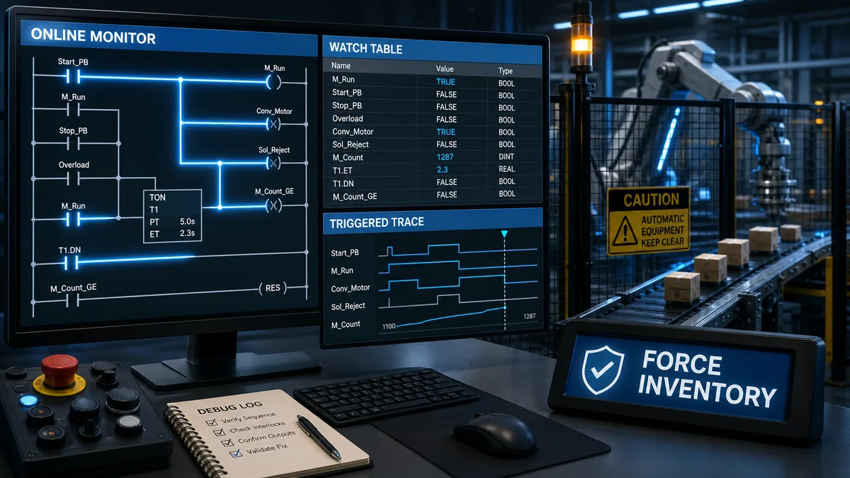
Use online monitoring to observe, not to assume. A highlighted contact, displayed tag value or green rung can be delayed, forced, aliased, overwritten later, sampled from a different task or disconnected from physical I/O. Confirm controller identity, project equality, operating mode, task schedule, communication freshness, forces, online edits and the exact meaning of the editor display before drawing a conclusion.
Prefer non-intrusive tools in this order: diagnostic/event logs, online/offline comparison, cross-reference, watch table, task-performance view and a triggered trace with a defined sample task, interval, trigger and pre/post buffer. A one-time write, a persistent force, an instruction override, simulation and a safety bypass are not interchangeable. Use the installed platform's exact terminology and an authorized test plan.
If a controlled change is necessary, give it an owner, scope, expiry, expected result, abort condition and rollback. Verify the baseline first, change one thing, repeat the same test, compare before and after, then either accept through change control or restore. Handover is incomplete until pending/test edits are closed, temporary code and breakpoints are removed, the force/override inventory is explicitly zero or approved, the final project is backed up, and the process owner accepts the restored state.
Establish authority, safety and test scope
Treat online access as control access
An engineering workstation can change tags, modes, outputs, parameters, tasks and logic while connected to equipment. A seemingly harmless force, write, breakpoint, download or test edit can start motion, suppress an interlock, make data stale, stop a task or change the recovery state after a fault. Remote access does not remove physical consequences.
Follow the facility's risk assessment, hazardous-energy, electrical safe-work, functional-safety, cybersecurity, management-of-change and operating procedures. OSHA 1910.147 covers unexpected energization, startup and stored-energy release during covered servicing; control-circuit devices such as push buttons and interlocks are not energy-isolating devices. OSHA 1910.333 requires appropriate electrical work practices and generally requires exposed live parts to be de-energized unless the stated exceptions and protections apply. This page does not determine whether a particular task falls within either rule.
| Authorization question | Minimum evidence before connection or test | Unsafe assumption prevented |
|---|---|---|
| what equipment can move, heat, pressurize or release material? | current process state, affected area, energy sources and responsible operator | “I am only watching software” |
| what may this account change? | named identity, role, approved access path and audit/log availability | read-only-looking screen means read-only access |
| what is the test envelope? | exact inputs, modes, setpoints, outputs, duration and exclusion zone | an unbounded production experiment |
| which protective functions are independent? | approved safety design, signatures and validation constraints | standard logic monitoring proves safety behavior |
| who can abort and restore? | named owner, communication channel, stop criteria and restoration sequence | engineer remains the only person who knows the temporary state |
| what must be preserved? | project, diagnostics, recipes/setpoints, retentive state, forces, edits and timestamps | the test destroys the evidence or rollback |
Define an observable test without commanding the hazard
Choose a repeatable event that the approved procedure already permits: a simulation stimulus, bench input, existing operator action, captured production occurrence or isolated dry-cycle condition. State the starting mode and sequence state, the action, the expected transition, maximum allowed time, permitted outputs, independent observations and abort rule. Do not create the condition by bypassing a guard, defeating a safety function or forcing a dangerous output.
For an intermittent production fault, observation may be the only approved first step. Configure logs or a trace in advance, let the normal event trigger the capture, and preserve the data. “Make it fail again” is not a sufficient plan when the consequence is equipment damage, product loss, environmental release or injury.
Prove that the online context is the right one
Verify controller, project and operating state
Before reading logic, identify the controller by asset, network path, catalog/type, serial or other trusted identity, firmware, application name/revision and time. Compare the online application with the controlled offline project. Record whether differences, pending edits, accepted/test edits, temporary routines, forces, overrides or changed parameters exist. An upload from an unknown controller is evidence of the current online image, not automatically the validated engineering master.
| Context item | Evidence to capture | Why debugging fails without it |
|---|---|---|
| controller identity | asset, path, hardware identity, firmware and timestamp | engineer monitors or changes the wrong target |
| project identity | repository revision, checksum/signature where available, online/offline comparison | displayed logic differs from the approved source |
| execution state | Run/Stop/Test mode, enabled tasks/programs/routines and inhibits | logic is visible but not executing as assumed |
| temporary state | all forces, writes, overrides, bypasses, edits and breakpoints | an earlier test manufactures the symptom |
| I/O and data freshness | module/connection quality, producer age, timestamps and update status | a plausible stale value is treated as current truth |
| time basis | controller, HMI, historian and capture-clock offset | events are placed in the wrong order |
Preserve a baseline before touching values
Export or screenshot the smallest evidence set that can reproduce the current conclusion: online/offline comparison, relevant logic, tag values with units and quality, cross-reference results, task statistics, event/fault log, trace configuration and samples, force/edit inventory, current sequence state and independent process observations. Record the test ID and clock source.
A screenshot of one green rung is weak evidence because it omits what wrote the tags, what executed afterward, whether a force was installed and when the screen refreshed. A stronger baseline relates a controlled stimulus and timestamp to the producer, logic evaluation, command, output and feedback while preserving the task and project context.
Locate the first expected-versus-observed divergence
Trace one event through every ownership boundary
Write the expected state at each boundary before examining the online values. For a conveyor start, that might be: StartRequest true, ModeAuto true, SafetyPermissive true from the validated interface, SequenceState Ready, MotorCommand true, output channel commanded, contactor feedback true and motion proven before the timeout. The actual names and safety architecture come from the project and approved design.
Then capture observed state for the same event and time window. If StartRequest never becomes true, do not rewrite the motor rung. If MotorCommand becomes true but module command remains false, investigate mapping, ownership, force and I/O status. If the module commands but independent feedback stays false, program logic may have done exactly what it was designed to do; the field/output path has another owner.
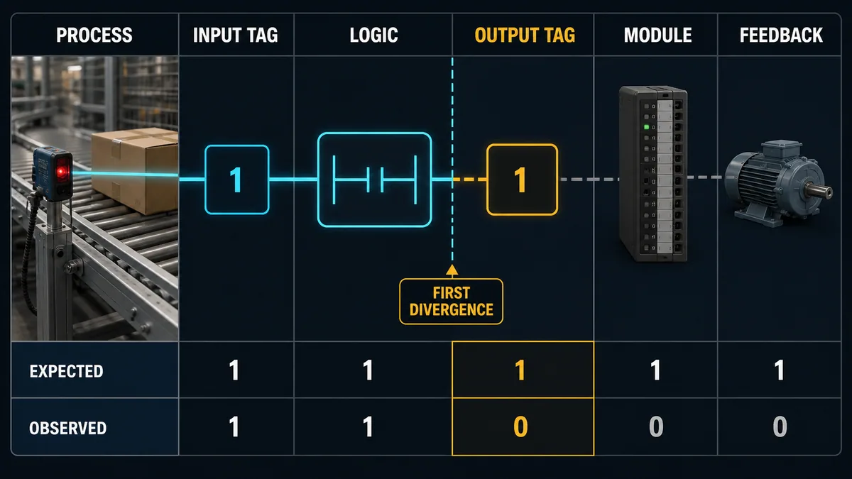
| Boundary | Expected evidence | Observed evidence to record | If this is the first divergence |
|---|---|---|---|
| process/stimulus | defined physical or simulated condition | independent sensor/process observation and time | test setup or process condition |
| producer/raw input | fresh, good-quality state from the intended source | raw value, quality, module/connection and source timestamp | field/I/O/communications owner |
| mapped/application tag | exact conversion or alias from producer | mapping, scale, alias and all writes | data ownership/mapping |
| logic condition/state | permitted transition in the executing task | rung/expression, state, call path and evaluated operands | program condition or state model |
| output command | one intentional writer produces expected command | every write, force, owner and final task value | write order/ownership/override |
| module/channel | connection accepts the intended command | module status, channel command and configured behavior | I/O configuration or channel path |
| independent feedback | equipment reaches defined result in time | auxiliary feedback, speed/position/process response and alarm | actuator/process, not necessarily program |
Separate absence of evidence from evidence of absence
A contact that is not highlighted on one screen refresh does not prove it was never true. A Boolean pulse may be shorter than the communications refresh, a routine may not be scheduled, a task may pre-empt another, or the editor may show a value at a different point in the execution cycle. Likewise, a displayed true value may be forced or stale. If timing affects the conclusion, move from visual monitoring to a target-resident trace, event log or application-owned diagnostic counter whose semantics are documented.
The PLC input/output troubleshooting guide owns electrical and module-to-field diagnosis. The PLC communication troubleshooting guide owns network and freshness failures. This guide owns the program-execution boundary after those producers are shown to be correct.
Read online monitoring without overclaiming
Know what the editor actually displays
Online ladder highlighting is a visualization built from controller data and tool semantics. It may indicate rung-condition flow, instruction state or operand value rather than actual current, voltage, motion or process truth. With aliases, mapped tags, produced/consumed data and I/O forcing, the value the program sees can differ from the raw source or physical result.
Rockwell's current glossary gives a particularly important product-specific example: with forces applied, Logix Designer displays input tag values as seen by program logic, while output tag displays are described without forces applied. That does not define other platforms, and it means “the screen says true” must be paired with the force state and the exact surface being viewed. Siemens documentation separately distinguishes transient modifying from forcing that can be retained on the memory card for the described S7-1500 family. Treat names such as modify, write, set, force and override as vendor terms, not synonyms.
| Display evidence | What it may establish | What it cannot establish alone |
|---|---|---|
| highlighted contact/rung | editor reports a logic state at its observation point | physical input, uninterrupted truth or final output state |
| watch-table value | selected symbol/address had a displayed value at refresh | source ownership, freshness, task phase or absence of another write |
| output tag true | application command or viewed output member is true under tool semantics | voltage at terminal, actuator movement or unforced physical command |
| input tag true | program-visible input is true under tool semantics | sensor correctness, no force, correct mapping or physical continuity |
| sequence step active | selected state bit/number is active | transition code is executing once, exclusively or correctly |
| timer done/status | stored instruction state is displayed | call continuity, correct time base, no state overwrite or process timing |
Use cross-reference to find every producer and consumer
For each divergent tag, find declarations, aliases, external access, HMI/SCADA writes, communications mappings, message instructions, input/output mappings and every read or write in every scheduled program. Include structured-text assignments, function-block outputs, sequencers, array/indexed access, copy/move instructions, indirect references and generated library code. Some tools cannot resolve every dynamic reference; document that limitation.
Classify each occurrence as producer, transformation, consumer or diagnostic-only reference. A shared command tag with writers in manual mode, automatic sequence, fault handling and initialization is not understood until order and mutual exclusion are proven. Rename or refactor later under change control; first preserve evidence of the existing behavior.
Build a watch table with meaning, not a tag dump
Group a small set of signals by causal role and include units, quality and age where available. For a missed motor start, useful groups are request/mode, permissives/interlocks, sequence state/transition, command/owner, output/channel status and feedback/timeout. Watching hundreds of unrelated tags increases refresh load and hides the ordering question.
Record the watch-table configuration with the evidence. A value without its symbol scope, datatype, representation, controller time and force/write state can be misread later. Decimal 16 may be a count, bit mask, enumerated state or raw word; a displayed 1 may be Boolean, integer or a bit within a mapped structure.
Reason about tasks, scan order and state
Replace the universal scan myth with the target schedule
The teaching model “read inputs, execute logic top-to-bottom, write outputs” is useful for some simple cyclic controllers, but it is not a universal timing specification. Modern controllers may use continuous, periodic and event tasks; task priorities and pre-emption; program/routine schedules; asynchronous I/O updates; immediate instructions; communications producers; and motion or safety execution domains. Use the exact controller documentation and project schedule.
Rockwell documents that Logix tasks schedule programs in organizer order, higher-priority tasks can pre-empt lower-priority tasks, and watchdog behavior applies when execution exceeds the configured limit. Its task monitor exposes scan times, trigger intervals and overlap counts. CODESYS trace documentation explains that a trace is assigned to a task and, for the described runtime mechanism, sampling occurs after statements in that task cycle. Those facts are useful examples of why the observation phase matters; they do not define Siemens, Mitsubishi, Schneider or every CODESYS target.
| Scheduling question | Evidence | Common false conclusion |
|---|---|---|
| is this routine called? | task/program/routine schedule and call path | visible routine must execute |
| when is the producer updated? | I/O/communications update model and timestamps | input is frozen for the entire controller cycle |
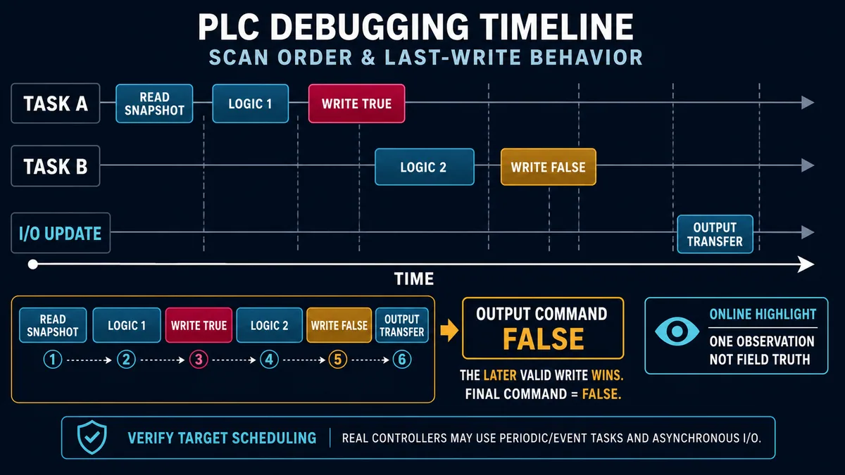
| can another task pre-empt this one? | task type, priority, trigger, execution and overlap statistics | source order equals wall-clock order |
| where is the tag last written? | all writers plus actual execution order | first true coil owns final state |
| did a pulse occur between screen refreshes? | target-resident trace/event counter at suitable sampling | no highlight means no pulse |
| is task timing degraded? | last/max scan, jitter/interval, overlaps and watchdog/event history | logic fault when CPU load is the cause |
Diagnose multiple writers and last-write behavior
Search every writer of the final command and its underlying members. Record which writer executed, with what condition, in which task and at what phase. In a simple sequential execution path, a later assignment can supersede an earlier one before the output update. In multi-task or asynchronous systems, priority, pre-emption and I/O update semantics matter as well.
Do not “fix” a last-write problem by forcing the command true. That only masks ownership. Define a single command owner or an explicit arbitration block, with named requests, priority, mode and reason diagnostics. The permanent design should make it possible to answer why the final command is on or off without watching every rung.
Inspect stateful instructions and restart paths
Timers, counters, latches, edge detectors, function blocks, sequencers and state machines carry history. Their current outputs may depend on previous calls, enable continuity, reset order, retentive configuration, first-scan/startup logic, mode changes and instance identity. Reusing one edge instance for two signals or conditionally skipping a stateful block can couple behavior that looks random in a snapshot.
Capture both the current state and the transition evidence. For a sequence, record current step, previous step, transition request, each guard, command ownership, time in state, timeout and reset/recovery reason. A one-hot step array with zero active steps, two active steps or an invalid numeric state should produce a defined diagnostic path rather than silently continue.
Live mini-lab
Try it: press START, then STOP
A stop-dominant seal-in rung: START latches the motor output through its own contact, and STOP breaks the circuit.
Watch the output lamp: it stays on after START until you press STOP.
Free to start · runs in your browserOpens plcsimulationsoftware.com — same team
Choose the least intrusive debugging tool
Escalate from observation to intervention
Use the lowest-impact surface that can resolve the hypothesis. An event log may answer when a task stopped. Cross-reference may reveal a second writer. A watch table may confirm a stable wrong state. A trace may capture a short ordering fault. Only then consider a controlled write, simulator experiment, temporary instrumentation, online edit or force.
| Tool | Best question | Main limitation or risk | Evidence to retain |
|---|---|---|---|
| diagnostics/event log | what fault, mode or configuration event happened first? | rollover and unsynchronized clocks | original export, clock offset and controller identity |
| online/offline compare | does running code/config match the approved project? | uploaded values and generated objects may need interpretation | comparison report and both revision identities |
| cross-reference | who reads and writes this symbol/address? | indirect/external references may be incomplete | search scope, unresolved references and writer map |
| watch/data table | what are selected values now? | refresh can miss pulses and omit force/source context | table definition, snapshot and timestamp |
| task monitor | is execution time, interval or overlap abnormal? | reset statistics can erase history | before/after last/max/overlap and reset time |
| triggered trace | what happened around a short or intermittent event? | sampling/trigger/buffer can misrepresent it | configuration, raw samples and clock basis |
| simulator/offline test | does the program produce expected behavior in its model? | plant, I/O, firmware and timing fidelity are limited | model assumptions, test vectors and result |
| controlled online change | does one authorized code change correct the cause? | changes running behavior and project state | approval, diff, test, rollback and final backup |
| force/override | can an approved isolated test substitute one boundary? | persistent/unexpected actuation and masked logic | owner, point, value, enable state, expiry and removal proof |
Add temporary instrumentation only with removal criteria
Sometimes the best evidence is a diagnostic counter, first-out latch, transition-reason code or event record added to the application. Design it so it does not command equipment, change timing beyond the evaluated tolerance, expose sensitive data or persist without ownership. Give it a stable test identifier and defined removal or production-hardening decision.
Instrumentation overhead can change the failure being observed. Compare task performance before and after, especially for high-rate tasks, motion, communications and heavily loaded controllers. If the added trace or logic changes the symptom, that is evidence about timing sensitivity—not permission to ignore the effect.
Govern writes, forcing and overrides
Distinguish monitor, write, force and application override
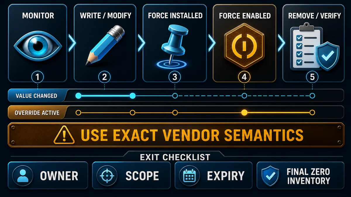
A monitor reads a value under the tool's observation model. A write or modify operation usually changes a value at a defined instant or under a temporary control job. A force can replace or override program-visible I/O behavior and may have separate installed and enabled states. An application override is logic deliberately designed to select a test/manual source. Vendor behavior varies by target, data type, I/O direction, operating mode, safety context and project configuration.
Siemens' S7-1500 system documentation describes modifying as an online function not stored in the CPU and ended through the relevant table or online connection, while the documented force job is written to the memory card and retained after power off. Rockwell distinguishes forces installed from forces enabled; its current controller documentation warns that enabling can make all existing force values active immediately. CODESYS provides a Watch All Forces view and separate unforce actions. These differences are exactly why a generic “right-click and force” recipe is unsafe.
| Intervention | Define before use | Verify during test | Required exit evidence |
|---|---|---|---|
| one-time write/modify | exact symbol, datatype, timing and program overwrite behavior | value and process consequence at the intended observation point | control job ended; expected owner restored |
| I/O force | physical/process consequence, direction semantics, installed/enabled lifecycle | visible force status, affected point and independent equipment state | force removed or approved; global and local inventories checked |
| internal tag force | all consumers, task behavior and persistence | program-visible value and any hidden writers | unforced value returns to designed ownership |
| application test/manual override | engineered interlocks, permissions, indication and timeout | selected source, mode and alarms remain correct | override off, mode restored and audit recorded |
| temporary bypass | explicit risk review and compensating protection | owner present, expiry active and bypass indication visible | bypass removed and protective function revalidated |
Make every temporary state expire visibly
The test record should name the exact point, requested value, reason, approving owner, installer, start time, expiry, affected equipment, preconditions, abort condition and removal verifier. Display forces or bypasses to the responsible operator where the platform and procedure require it. Never leave a force because “the program will overwrite it”; a force exists precisely to alter ordinary ownership under platform-specific rules.
Before enabling a force set, inspect the complete installed-force list, not only the point being added. A dormant force installed during an earlier job may become active with the new enable action. After the test, remove or transition each force according to the exact vendor procedure, then prove the global status and every relevant point. Power cycling is not a universal force-removal method.
Keep safety and standard logic separate
Do not use standard PLC forcing guidance to test a safety application. Safety controllers can restrict edits and forces, use signatures and locked states, require special modes, and demand validation under the product safety manual and the facility's functional-safety lifecycle. A standard output command or HMI permissive is not proof of a safety output or final element.
Design a trace that can answer the timing question
Choose signals from the hypothesis
A useful trace is a test instrument, not a colorful trend. Start with one timing question: “Did feedback fall before the command, or did the command fall first?” Select the smallest set that distinguishes hypotheses: request, decisive permissive, sequence state, command, output status, feedback and fault/timeout. Include quality or age when the producer can become stale.
Assign the sample task or time base that observes the relevant writes. Choose a sample interval short enough for the shortest meaningful event, subject to target limits and acceptable overhead. Define the trigger edge/condition, trigger level, pre-trigger history, post-trigger samples, buffer size, timestamp resolution and stop/rearm behavior. Save the configuration with the data so another reviewer can interpret the plot.
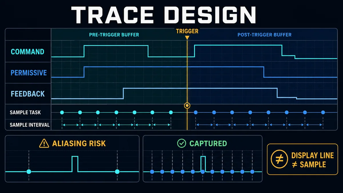
| Trace parameter | Design question | Failure mode if wrong |
|---|---|---|
| variables | which signals distinguish the competing causes? | too many unrelated tags or missing decisive boundary |
| sample task/time base | when relative to the writes are values captured? | correct event appears in a misleading order |
| sample interval | what is the shortest pulse or delay that matters? | aliasing or a missed transient |
| trigger | what exact edge/condition identifies the event? | buffer fills on irrelevant activity or never captures |
| pre-trigger depth | how much causal history is needed? | only consequence is visible |
| post-trigger depth | how long does response/recovery take? | timeout or feedback result falls outside capture |
| timestamp/clock | how will PLC trace align with HMI, drive or historian? | cross-system order is guessed |
| resource load | what CPU/memory/communications cost is acceptable? | instrumentation changes task performance or plant behavior |
Detect aliasing and display interpolation
Sampling a 5 ms pulse every 10 ms can miss it completely depending on phase. Even if a trend draws a smooth line between two samples, the controller did not measure every point on that line. For a conclusion such as “the permissive dropped before the output,” verify that sample resolution and observation phase can distinguish the edges with adequate margin.
Do not infer electrical waveform integrity from a PLC variable trace. Input filters, module conversion, network updates and task sampling already transform the physical event. Use appropriately rated measurement equipment and qualified procedures when the physical signal shape matters, then align that evidence with the controller trace.
Preserve raw samples and configuration
Export the raw trace or supported native file, not only a cropped screenshot. Retain variable paths, datatypes, task, interval, trigger, buffer, timestamp basis, controller/project identity and any dropped-sample or resource warning. Mark annotations as analyst interpretations rather than altering the original data.
Control online edits and breakpoints
Treat the edit lifecycle as explicit machine state
Platforms distinguish pending, accepted, tested, assembled/finalized, canceled and untested edits in different ways. Rockwell's documented ladder workflow, for example, separates creating and accepting a pending rung edit from testing it; accepted insert logic does not execute until the edit is tested, and assembling commits the tested selection. A production handover with accepted-but-untested or test edits is an ambiguous controller state.
Before an online change, create a reviewed diff, identify affected tasks and outputs, verify backup/rollback, establish the test vector and acceptance criteria, and record who controls the test. During the test, observe both the intended result and unrelated critical functions. Afterward, either assemble/finalize under the approved workflow or cancel/restore, then compare online and offline projects again and archive the final master.
| Edit stage | Question to answer | Evidence required before advancing |
|---|---|---|
| proposed | what diagnosed cause does this exact diff address? | hypothesis, review and affected-function analysis |
| transferred/accepted | what is resident but not yet executing? | platform edit state and controller/program scope |
| test active | which old/new logic executes and what else is affected? | explicit test-state indicator and operator authorization |
| acceptance | did repeatable before/after evidence meet every criterion? | identical test vector, results and regression checks |
| finalize or rollback | which code is now authoritative? | closed edit state, comparison and saved controlled project |
| handover | are temporary states gone? | zero/approved forces, no breakpoints, instrumentation disposition and operator acceptance |
Use breakpoints only where halting is proven safe
A breakpoint can stop a task or application and prevent its I/O updates while other tasks or devices continue. CODESYS documentation notes target- and multi-task-specific behavior: a debug task can halt while other tasks continue, and an online change or download while stopped at a breakpoint can cause all tasks to halt. Conditional breakpoints can also slow execution. Other platforms differ.
Do not put a live production controller at a breakpoint because it resembles desktop software debugging. Use simulation, an isolated bench or a vendor-approved test mode when possible. If a breakpoint is authorized, define output/fallback behavior, task interactions, watchdog consequence, communications, motion/safety restrictions and recovery before enabling it. Remove and verify all breakpoints afterward.
Reproduce the fault in a simulator or controlled test
Build a minimal fault case
Use a simulator to isolate program logic from the field system and create repeatable test vectors. A useful case for “motor command flashes then turns off” contains two writers: an automatic sequence sets MotorCommand, and a later manual-mode arbitration path clears it because the mode-owner state is invalid. The test observes request, mode, permissive, state, both writer reasons, final command and feedback model over several scans.
| Test case | Starting state | Stimulus | Expected evidence | Diagnostic value |
|---|---|---|---|---|
| normal automatic start | Ready, Auto owner, all modeled permissives true | one StartRequest edge | state advances; auto writer true; final command remains true | proves intended baseline |
| invalid owner | Ready, owner neither Auto nor Manual | same StartRequest | auto request appears, arbitration clears command with reason | reproduces last-write symptom |
| permissive drops before start | Ready, Auto owner, one permissive false | same StartRequest | transition blocked; no command pulse | separates transition guard from overwrite |
| feedback never arrives | Run command maintained, modeled feedback false | allow timeout window | command remains per design; feedback timer produces defined fault | separates output command from process result |
| restart in active state | selected retentive/nonretentive setup | controlled simulated restart | state initializes or resumes exactly as specification | tests startup ownership |
The interactive lab should grade the reasoning, not reward indiscriminate toggling. Require the learner to identify the first divergence, select the relevant cross-reference result, configure a sufficient trace and explain why a force would mask the cause. Then repeat after changing only the arbitration logic or state initialization and compare the traces.
State what simulation does not prove
Simulation can prove behavior within its modeled instruction semantics, task schedule, I/O model and test data. It does not automatically prove target firmware behavior, real module updates, network timing, sensor physics, actuator response, drive state, electromagnetic effects, resource load, redundancy, safety execution or startup retention. Record the simulator version, model assumptions and unsupported instructions.
Promote a fix through offline tests, peer review, hardware-in-the-loop or FAT where required, then the approved site test and production observation. A passing browser or desktop simulation is evidence for logic intent, not authorization to download to an installed machine.
Commission the fix and close the evidence loop
Repeat the same test before and after
Use the same starting state, stimulus, load, observation points, sample configuration and acceptance window. Compare the first divergence and downstream behavior. A fix that makes the output turn on but breaks stop, fault, restart, manual mode or timeout behavior has not passed.
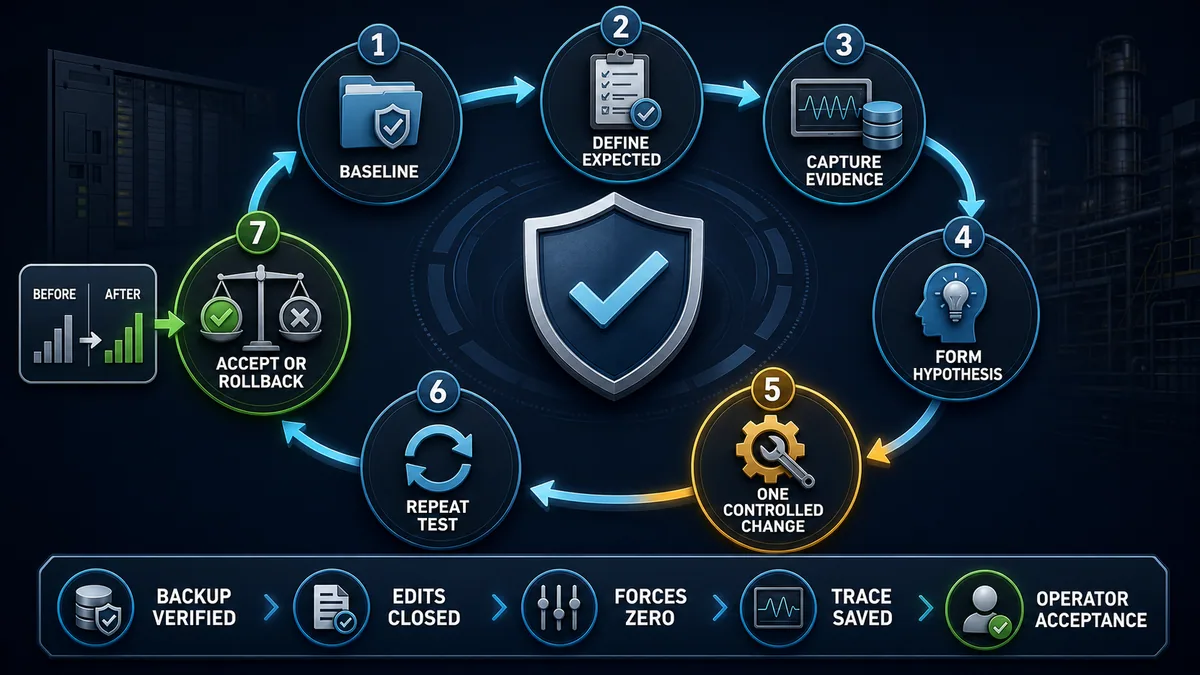
| Acceptance case | Evidence | Pass question |
|---|---|---|
| original failing condition | before/after trace and first-divergence matrix | is the diagnosed divergence removed for the stated reason? |
| normal start/stop | command, feedback, timing and operator result | do normal transitions remain deterministic? |
| permissive/interlock loss | cause, command removal and state transition | does the application take the specified response without hidden force? |
| mode transfer | owner, request arbitration and outputs | can manual/automatic ownership change without two writers fighting? |
| timeout/fault/reset | first-out cause, latch, acknowledgment, reset and recovery | are fault and reset separate and correctly sequenced? |
| restart/power recovery | retained state, initialization and safe resumption | does restart behavior match the approved specification? |
| task performance | last/max scan, interval/overlap and watchdog evidence | did the change avoid unacceptable timing impact? |
| final configuration | online/offline comparison, backup and audit | is the tested application the controlled master? |
Finish with a zero-surprise handover
List and close pending, accepted, test and temporary edits. Remove or formally approve every force, override, bypass, breakpoint and temporary instrument. Verify the platform's global indicators and the relevant point-level lists; do not rely on memory. Save the final project and trace evidence, record the deployed revision, restore authorized access and network paths, and obtain operator/owner acceptance.
Monitor for a defined duration or operation count that covers the original trigger. If the fault was weekly, five minutes of clean operation is weak evidence. Use an exposure metric such as cycles, batches, changeovers, starts or hours in the relevant operating state and state the residual uncertainty.
Write a falsifiable cause statement
“PLC glitch” is not a cause. A defensible record identifies the first divergence, mechanism and proof: “MotorCommand became true in the automatic sequence, then the later arbitration routine cleared it because ModeOwner initialized to None after a warm restart. A task-aligned trace and cross-reference showed the write order; initializing ownership through the approved recovery state removed the divergence across 200 simulated cycles, FAT restart cases and the authorized site test.”
Separate confirmed cause from contributing conditions and unknowns. Attach the project diff, before/after trace, test matrix, review, force/edit exit inventory and preventive action. Prevention may be single-writer arbitration, explicit transition-reason diagnostics, invalid-state handling, task-overlap monitoring, improved change control or a repeatable regression test.
Troubleshooting sequence by symptom
Follow the shortest decisive evidence path
| Symptom | First decisive check | Next evidence | Avoid |
|---|---|---|---|
| rung looks true but output is off | cross-reference every output writer and force state | task order, final command, module/channel and feedback | forcing output to “prove” the rung |
| input LED changes but contact does not | raw module/channel, mapped tag, quality and task update | alias/mapping, force and input filter/update timing | rewriting application logic first |
| contact flashes too quickly to see | target trace or event counter in relevant task | sample interval, trigger and pre/post buffer | concluding it never occurred from screen refresh |
| timer never completes | confirm instance is called continuously as designed | enable/reset order, time base, preset and task timing | modifying accumulated value as the fix |
| sequence stuck on one step | current/previous state and every transition guard | transition-reason code, mode and fault/reset path | setting the next state without finding the guard |
| output pulses then drops | all writers and task order | arbitration, fault logic, state transition and trace | extending pulse blindly |
| fault only after online change | edit state and exact diff | task performance, initialized data and before/after comparison | assembling edits before evidence capture |
| behavior changes after restart | retentive state and startup/first-scan logic | loaded project/data image, modes, clocks and communications readiness | forcing old values back without design proof |
| simulator passes but machine fails | list model boundaries and compare target evidence | I/O/network timing, module behavior, process feedback and firmware | calling the field system “random” |
| force indicator remains after test | inspect global and point-level installed/enabled inventory | exact vendor removal workflow and process restoration | power cycling as a generic cleanup |
Diagnostic answer map for PLC program debugging
| Question a technician or AI assistant may ask | Short, extractable answer | Evidence that decides it |
|---|---|---|
| How do you debug a PLC program? | Define one expected event, preserve the online context, then locate the first expected-versus-observed divergence from producer through logic, command and feedback. | project comparison, writer map, watch/trace and independent process evidence |
| Why is a PLC rung true but the output off? | Another writer, force semantics, task order, output mapping, I/O status or field feedback may differ from the viewed rung. | cross-reference, force inventory, task-aligned trace and channel status |
| What is PLC online monitoring? | It is an engineering view of controller values and logic state under product-specific refresh and force semantics, not direct proof of physical state. | tool manual, observation point, timestamps and independent evidence |
| What is the difference between writing and forcing a PLC tag? | A write changes a value under a defined write/control operation; a force overrides ordinary ownership under platform-specific lifecycle rules. | installed product documentation and global/point force status |
| How do I find what changes a PLC tag? | Cross-reference all direct, alias, mapped, indirect and external writers, then order the executing producers by task and call path. | complete writer map and target schedule |
| How do I capture an intermittent PLC fault? | Configure a target-resident trace or event record with decisive signals, suitable sample interval, trigger and pre/post buffer before the normal event occurs. | saved trace configuration and raw timestamped samples |
| Can a PLC breakpoint stop the machine? | It can halt a task or application and affect I/O updates while other execution may continue, so exact target behavior and safe outputs must be proven first. | controller/runtime documentation and isolated test plan |
| When is a PLC debug complete? | When the cause passes repeatable tests and the final project, edits, forces, overrides, breakpoints, evidence and operator handover are reconciled. | acceptance matrix, final comparison, backup and exit inventory |
Frequently asked questions
What should I capture before debugging a PLC online?
Capture controller and project identity, firmware, operating mode, online/offline differences, scheduled tasks, I/O/data quality, event logs, clocks, all forces and overrides, every edit state, current machine/sequence state and the approved test boundary. Preserve a baseline watch table or trace before changing values.
Why does PLC ladder logic show green when the machine is not running?
The highlight can represent program-visible logic state, not physical voltage or motion. The command may be overwritten later, forced under special display semantics, mapped to another channel, blocked by an I/O/drive owner, or waiting for feedback. Trace the final command through module state and independent equipment feedback.
How do I find multiple writers of a PLC output?
Cross-reference the output tag, aliases, mapped members and underlying address across every task, program and routine. Include structured-text assignments, copy/move/sequence instructions, indirect references, external/HMI writes and force state. Then order only the writers that actually execute during the failing event.
Is writing a PLC value the same as forcing it?
No. A write or modify action changes a value according to the platform's write lifecycle and may be overwritten by normal execution. A force overrides ordinary program or I/O ownership under different rules and may have separate installed/enabled or persistent states. Use the exact product manual.
Can I safely force a PLC input for troubleshooting?
Only within an authorized test whose process consequence, force semantics, owner, duration, abort and removal are defined. A forced input can make logic believe a field condition exists even when the device disagrees. Prefer simulation or isolated testing, never use generic forcing guidance for a safety application, and verify complete removal.
Why does a PLC Boolean pulse not appear in the watch table?
The pulse may occur between engineering-screen refreshes, in another task phase or before a later writer changes it. Use a controller-resident trace, event counter or first-out latch with suitable timing semantics. A missing highlight is not proof the pulse never occurred.
How fast should a PLC trace sample?
Fast enough to distinguish the shortest event and edge order relevant to the hypothesis, with margin, while staying within target resource limits. Choose the sampled task, interval, trigger and buffer together. A display line between samples does not create intermediate measurements.
Why does PLC behavior change after an online edit?
The edit may be pending, accepted, in test, finalized or interacting with initialized data, task timing and old/new logic zones under platform-specific rules. Record the exact edit state and diff, repeat the same test, check task performance and either finalize the proven change or roll back.
Should I use breakpoints on a running PLC?
Not unless the exact target's halt, I/O, multi-task, watchdog and recovery behavior is proven safe and authorized. A breakpoint can stop updates in one task while other tasks or physical equipment continue. Prefer simulation, traces, event logs or non-halting instrumentation for live production diagnosis.
How do I prove all PLC forces are removed?
Use the platform's global force status plus the complete point-level installed/enabled force inventory, then verify normal producer ownership and process state for every affected point. Record who checked it and when. Do not assume disconnecting, downloading or power cycling universally removes forces.
Sources, review scope, and limitations
This guide synthesizes primary regulator, cybersecurity and vendor documentation into a vendor-neutral diagnostic method. It deliberately omits universal force clicks, breakpoint steps, safety-logic tests and live output commands because their meaning and consequence vary by controller, firmware, project, machine and site procedure. The figures are conceptual and do not define program code, task schedules, I/O architecture, safety functions or authorization for installed-equipment tests.
- OSHA 29 CFR 1910.147: The Control of Hazardous Energy — scope, energy-control procedures and limits of control-circuit devices as isolation.
- OSHA 29 CFR 1910.333: Selection and Use of Work Practices — electrical de-energization, qualified-person and safe-work requirements.
- NIST SP 800-82 Rev. 3: Guide to Operational Technology Security — OT safety, reliability, access, change and security context.
- Rockwell Automation Studio 5000 Logix Designer Online Help, v38.01 — online monitoring, cross-reference, trends, force and security capability context.
- Rockwell Automation Logix Designer Glossary: Force — input/output display semantics and installed/enabled force definitions.
- Rockwell Automation ControlLogix 5590 Status Indicators — force-enabled and force-installed indicator behavior and cautions.
- Rockwell Automation: Edit Ladder Logic in Run Mode — pending, accepted, test and assembled rung-edit lifecycle.
- Rockwell Automation: Tasks — task scheduling, priority, pre-emption and watchdog context.
- Rockwell Automation: View Task Performance Details — scan time, trigger interval and task-overlap monitoring.
- Siemens S7-1500 / ET 200MP System Manual, 11/2024 — watch/force tables and the documented distinction between modifying and forcing.
- Siemens Trace and Logic Analyzer Function Manual, 11/2025 — trace recording, cycles, triggers and analyzer behavior.
- Siemens Diagnostics Overview for S7-1200 and S7-1500 — watch/force tables, online/offline comparison and diagnostic tools.
- CODESYS: Forcing and Writing of Variables — write/force workflow and Watch All Forces inventory.
- CODESYS: Data Sampling with Trace — task-cycle sampling, timestamps, buffers, triggers and exports.
- CODESYS: Trace Configuration — sampled task, variables, trigger and buffer configuration.
- CODESYS: Using Breakpoints — multi-task, I/O-update and online-change behavior at breakpoints.
Now run it · free to start
Learn a repeatable way to find the fault
Split a stopped machine into input, logic, output and physical response, and take the measurement that proves each stage. Practised on simulated machines. Free to start.
Ownership disclosure: PLC Programming IO and PLC Simulation Software are operated by the same publisher.
PLC Programming IO Editorial Team
Industrial automation education, references, and software testing
The PLC Programming IO Editorial Team publishes sourced industrial-automation education and documents how material is reviewed, tested, and corrected. A team byline means the publisher is responsible for the page; it does not represent a fictional person or imply an engineering licence.
Coverage:
- • PLC programming concepts and examples
- • Vendor software tutorials and comparisons
- • SCADA, HMI, protocols, and instrumentation
- • Training, careers, and reference material
Review standard:
- • Prefer primary and official sources
- • Record software versions when material
- • Separate tested facts from estimates
- • Publish material corrections
Important scope note
This site provides education, not project-specific engineering approval. Safety, code, and compliance decisions require a qualified person with access to the actual machine and jurisdiction.