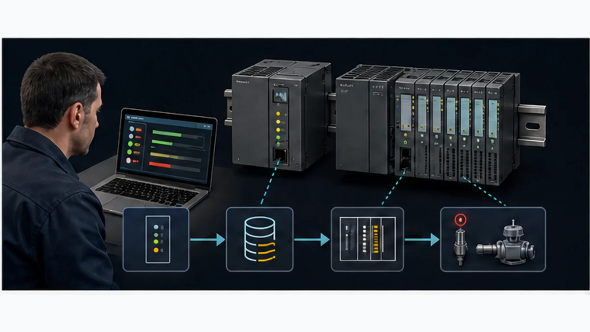
Siemens S7-1200 PLC: Selection, Programming and Commissioning
Identify, select and program a Siemens S7-1200 or S7-1200 G2 with a version-scoped TIA Portal workflow, tested block architecture, simulation limits and commissioning evidence.
The Siemens S7-1200 is a compact SIMATIC controller family engineered with STEP 7 in TIA Portal. A reliable first project follows nine evidence gates: identify the exact generation, article number, hardware and firmware; define the application; select compatible CPU/modules/accessories; configure the matching TIA device; map symbolic I/O; structure OBs, FBs, FCs and DBs; compile and simulate the supported scope; download through an authorized change; then commission each channel, mode, sequence, diagnostic and recovery case against an approved test.
This guide covers both the established S7-1200 family and S7-1200 G2. Treat them as separate compatibility rows. Siemens states that S7-1200 G2 modules are not hardware-compatible with the earlier generation, and capability also varies by CPU, firmware and engineering release. A label such as “Siemens 1200 PLC” is not enough for design, replacement, software or troubleshooting.
What this S7-1200 guide owns
| Task | Correct owner | Boundary |
|---|---|---|
| select and program an S7-1200 first project | this page | CPU identity, architecture, TIA setup, I/O, blocks, test, download and commissioning |
| choose across LOGO!, S7-1200, S7-1200 G2, S7-1500 and software controllers | Siemens S7 family guide | family/application selection |
| learn general Siemens PLC programming | Siemens programming tutorial | broader TIA, LAD/SCL and cross-family workflow |
| learn the engineering environment | TIA Portal tutorial | software navigation and shared engineering workflow |
| implement an S7-1200 network/protocol | PROFINET, OPC UA, IO-Link, CANopen or EtherCAT gateway | protocol-specific compatibility, mapping and diagnostics |
| diagnose an installed Siemens system | Siemens PLC error codes and diagnostics | online/offline compare, buffer, I/O and recovery evidence |
The proposed /guides/siemens-1200-plc alias should redirect here rather than compete with an established, already-linked model-specific owner.
Download the S7-1200 project and commissioning checklist (CSV)
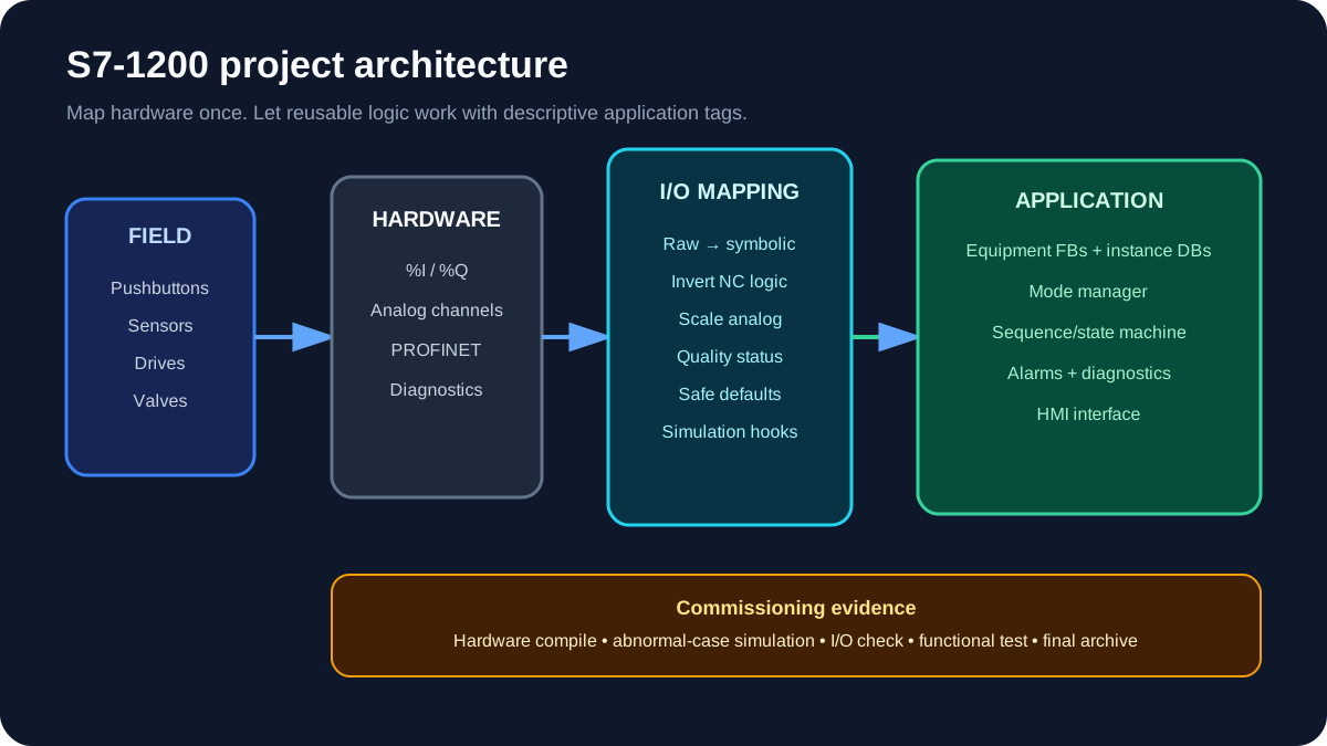
S7-1200 project roadmap
| Stage | Deliverable | Proof before continuing |
|---|---|---|
| Select | CPU, signal modules, communication and power plan | Order numbers checked against current manuals |
| Configure | TIA Portal device and network configuration | No unresolved module or compatibility warnings |
| Map | Symbolic I/O and safe default states | Every field point reconciled to the I/O list |
| Structure | OBs, FBs, FCs and DBs | Clear ownership of state and commands |
| Program | Sequence, modes, alarms and diagnostics | Normal and abnormal cases reviewed |
| Simulate | Repeatable test cases | Test record for permissives, trips and recovery |
| Commission | Controlled download and field checks | Signed I/O and functional test results |
1. Identify the exact controller
Record the full article number, hardware generation, firmware revision, supply voltage and onboard I/O variant. “S7-1200” is not a complete hardware specification.
Siemens describes S7-1200 G2 as the second generation of the family, with integrated PROFINET, onboard I/O, high-speed counting and motion capabilities in a narrower footprint. The official S7-1200 G2 system manual also documents compatibility differences from the first generation. Check its associated product-information updates before wiring: Siemens issued an August 2025 terminal-block safety update for specific relay-related connectors and modules.
For an existing machine:
- Photograph the CPU and module order numbers.
- Upload or archive the current project before making changes.
- Record firmware and the TIA Portal version used by the validated project.
- Confirm replacement compatibility in Siemens Industry Online Support.
- Treat generation changes as migrations, not drop-in substitutions.
2. Size the CPU and I/O
Count more than digital points. The controller decision should include:
- digital inputs and outputs, including voltage and output technology;
- analog ranges, resolution and isolation needs;
- high-speed counters, pulse outputs and motion axes;
- PROFINET devices and other communications;
- work memory and retained data;
- expansion-module limits and physical width;
- safety requirements, which may require a fail-safe CPU and approved design process;
- future spare capacity.
Define growth allowance from the approved machine lifecycle, physical panel, power, thermal, slot, memory, performance and network requirements. Do not copy a universal spare percentage into every project or hide undefined scope inside “spares.” Reserve and label the channels, terminals, addresses and capacity that the project actually approves.
3. Create the TIA Portal device
Create a project, add the exact CPU from Devices & networks, and select the order number and firmware that match the hardware. Then:
- Add signal and communication modules in physical order.
- Set the device name and IP parameters from the approved network schedule.
- Configure channel properties and diagnostics.
- compile the hardware configuration;
- save a baseline archive before application logic begins.
If the installed device is absent from the catalog, stop and resolve the TIA Portal, hardware-support-package or firmware compatibility issue. Choosing a “close enough” CPU creates unreliable diagnostics and download risk.
4. Build a symbolic I/O map
Direct physical addresses scattered through the program make migrations and troubleshooting harder. Create one mapping routine that transfers physical I/O to descriptive application tags.
| Physical point | Raw tag | Application tag | Meaning |
|---|---|---|---|
%I0.0 |
DI_StartPB |
Cmd.StartPB |
Start pushbutton input |
%I0.1 |
DI_StopHealthy |
Perm.StopCircuitOK |
Healthy stop circuit |
%I0.2 |
DI_OverloadHealthy |
Perm.MotorOL_OK |
Motor overload healthy |
%Q0.0 |
DO_MotorContactor |
Out.MotorRun |
Contactor command |
Name a signal by what it means when TRUE. OverloadHealthy is clearer than Overload because it tells the reader how the normally-closed field circuit is interpreted.
5. Structure OBs, FBs, FCs and DBs
- Organization blocks (OBs) define execution entry points. Keep the main cyclic OB readable.
- Function blocks (FBs) own reusable behaviour and persistent instance data—for example a motor, valve or pump.
- Functions (FCs) suit stateless calculations or conversions.
- Data blocks (DBs) hold instance data, configuration, recipes and shared process values.
A useful rule is: the main OB should coordinate, not contain the entire machine.
OB1
 ├─ FC_MapInputs
 ├─ FB_ModeManager
 ├─ FB_Conveyor_01
 ├─ FB_Pump_01
 ├─ FC_AlarmSummary
 └─ FC_MapOutputs
For each equipment FB, separate:
- requests: auto start, manual start, stop, reset;
- permissives: conditions required before starting;
- interlocks/trips: conditions that stop or prevent operation;
- outputs: run command and status;
- diagnostics: cause, timestamp or state useful to the HMI.
6. Program a motor as a state, not only a seal-in rung
A training motor can be reduced to a start/stop latch. A production motor normally needs mode, permissive, feedback, timeout and trip handling.
StartRequest := AutoStart OR (ManualMode AND StartPB);
ReadyToStart := StopCircuitOK AND OverloadHealthy AND ProcessPermissive;

IF ResetPB AND OverloadHealthy THEN
    TripLatched := FALSE;
END_IF;

IF RunCommand AND NOT RunFeedback AND StartFeedbackTimer.Q THEN
    TripLatched := TRUE;
END_IF;

IF StopRequest OR NOT ReadyToStart OR TripLatched THEN
    RunCommand := FALSE;
ELSIF StartRequest THEN
    RunCommand := TRUE;
END_IF;
Run Structured Text in the simulator
This is an illustrative pattern, not safety logic. Emergency-stop and other safety functions belong in a risk-assessed safety system using approved components and validated safety software.
7. Simulate the abnormal cases
PLCSIM can verify application behaviour that does not depend on unavailable hardware or exact device timing. Build a test sheet before opening the simulator.
Minimum motor tests:
- Start with all permissives healthy.
- Start with one permissive missing.
- Remove a permissive while running.
- Apply overload while stopped and while running.
- Fail to receive running feedback.
- Restore feedback after timeout.
- Switch Auto/Manual during operation.
- Cycle power or restart the CPU and verify retained state intentionally.
Record expected output, observed output and pass/fail. Watching a green rung once is not a test record.
8. Download without creating an uncontrolled start
Before download:
- use an approved maintenance window;
- identify who controls the machine;
- place outputs and drives in a safe condition;
- compare the accessible device by order number, MAC/IP details and station name;
- review what changes on download or restart;
- know how to return to the validated version.
After download, prove inputs first. Then force or command outputs only under the site's commissioning procedure. Remove every force, verify the force table is empty and archive the commissioned project.
S7-1200 troubleshooting map
| Symptom | First checks | Frequent cause |
|---|---|---|
| CPU not found | PG/PC adapter, subnet, cable, accessible devices | Wrong interface or network mismatch |
| Hardware compile error | Order number, firmware, module position | Catalog selection does not match hardware |
| Input LED on, tag false | Address/channel configuration and mapping | Wrong address or mapped tag |
| Output tag true, device off | Output LED, supply/common, interposing relay | Field power or wiring issue |
| Unexpected startup after download | retained state, startup OB, mode logic | State not initialised intentionally |
| HMI value stale | connection, DB access, tag path | HMI connection or optimised-access mismatch |
| Intermittent PROFINET fault | device name, duplicate IP, cable, topology | Identity or physical-layer problem |
Project quality checklist
- Exact CPU, firmware and module order numbers are documented.
- Hardware, network and safety requirements are separated.
- All physical I/O is mapped to descriptive tags.
- Outputs have intentional safe/startup states.
- Equipment logic has permissive, trip and feedback behaviour.
- HMI commands cannot bypass PLC interlocks.
- Simulation covers abnormal and restart cases.
- Download and rollback plans are approved.
- Field I/O checks and functional tests are recorded.
- The final project archive matches the running controller.
Live mini-lab
Try it: press START, then STOP
A stop-dominant seal-in rung: START latches the motor output through its own contact, and STOP breaks the circuit.
Watch the output lamp: it stays on after START until you press STOP.
Free to start · runs in your browserOpens plcsimulationsoftware.com — same team
Build an S7-1200 compatibility manifest before opening TIA Portal
The manifest is the highest-value artifact for a new design, retrofit or support call. It prevents the family name from hiding incompatible assumptions.
| Field | Example format | Why it controls the work |
|---|---|---|
| controller generation | established S7-1200 or S7-1200 G2 | separates hardware/accessory architecture |
| CPU article number | exact 6ES7... order number from label/project |
selects the real device, I/O and capabilities |
| hardware/firmware | recorded from device and project | controls supported functions and engineering compatibility |
| TIA Portal/STEP 7 | exact edition, version and update | controls catalog, compilation and project opening |
| modules/accessories | article number, slot and firmware | prevents “same-looking” substitution |
| network identity | approved PROFINET name, IP/subnet and topology | prevents connecting to or renaming the wrong asset |
| application roles | controller, I-device/device, OPC UA server, motion, safety | turns feature claims into explicit requirements |
| validated archive | file hash/name, date, owner and backup location | establishes rollback and running-project provenance |
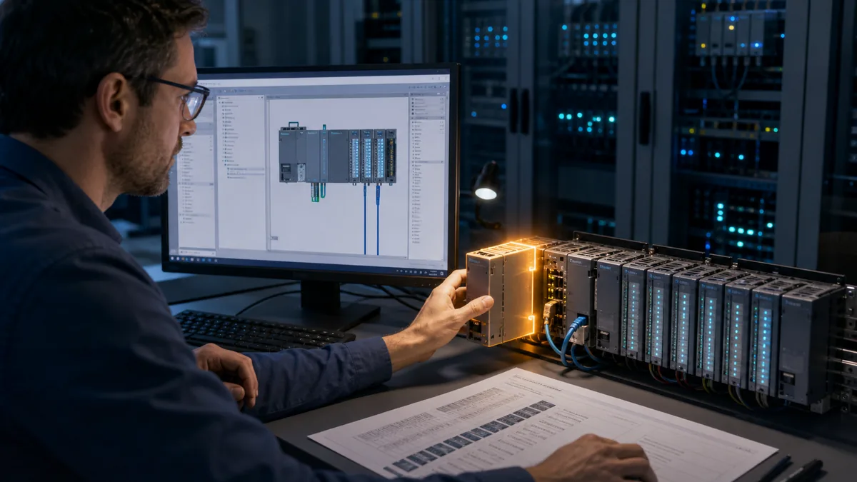
For replacement, compare more than supply and point count. Verify terminal/block compatibility, output technology and current, analog signal type/representation, high-speed channels, communication roles, memory, task/performance requirements, panel fit, environmental approvals, engineering version and downstream devices. For G2, consult both the current system manual and product-information/manual updates; a product update can change a wiring or connector decision after the base manual was published.
Download the S7-1200 compatibility manifest and preserve source URLs and review dates for every decisive row.
Convert requirements into a testable S7-1200 design
Do not start CPU selection with a guessed part number. Start with a requirement ledger.
| Requirement group | Questions | Acceptance evidence |
|---|---|---|
| I/O | point type, voltage/range, isolation, update and diagnostic need? | approved I/O list and module/channel match |
| execution | cyclic/event workload, response, interrupts, high-speed functions? | task/OB design and measured trace under load |
| program/data | reusable equipment, recipes, retained state, trace/history? | memory/data design plus compile and restart tests |
| motion | axes, technology objects, pulse/train or networked drives? | exact supported CPU/firmware/device and motion tests |
| communications | PROFINET devices, S7 connections, web/OPC UA or gateways? | connection budget, security boundary and failure/recovery tests |
| safety | required risk reduction and validation lifecycle? | separate approved fail-safe architecture and validation plan |
| lifecycle | spares, migration, firmware, archive and support horizon? | documented compatibility and recovery strategy |
This page cannot provide a universal CPU recommendation because CPU catalogs and capability tables change. Use the current Siemens selection/configuration tools and the exact system manual. Keep assumptions visible: “two future drives” is a requirement; “select the next CPU up” is an undocumented response.
Structure the project so hardware and behavior can change independently
Keep physical I/O at a narrow boundary, convert raw data to application meaning, then execute equipment/sequence logic on symbolic data. Map final commands back through one output boundary. This makes an address, module or generation change easier to review and prevents physical addresses from becoming a hidden API across the project.
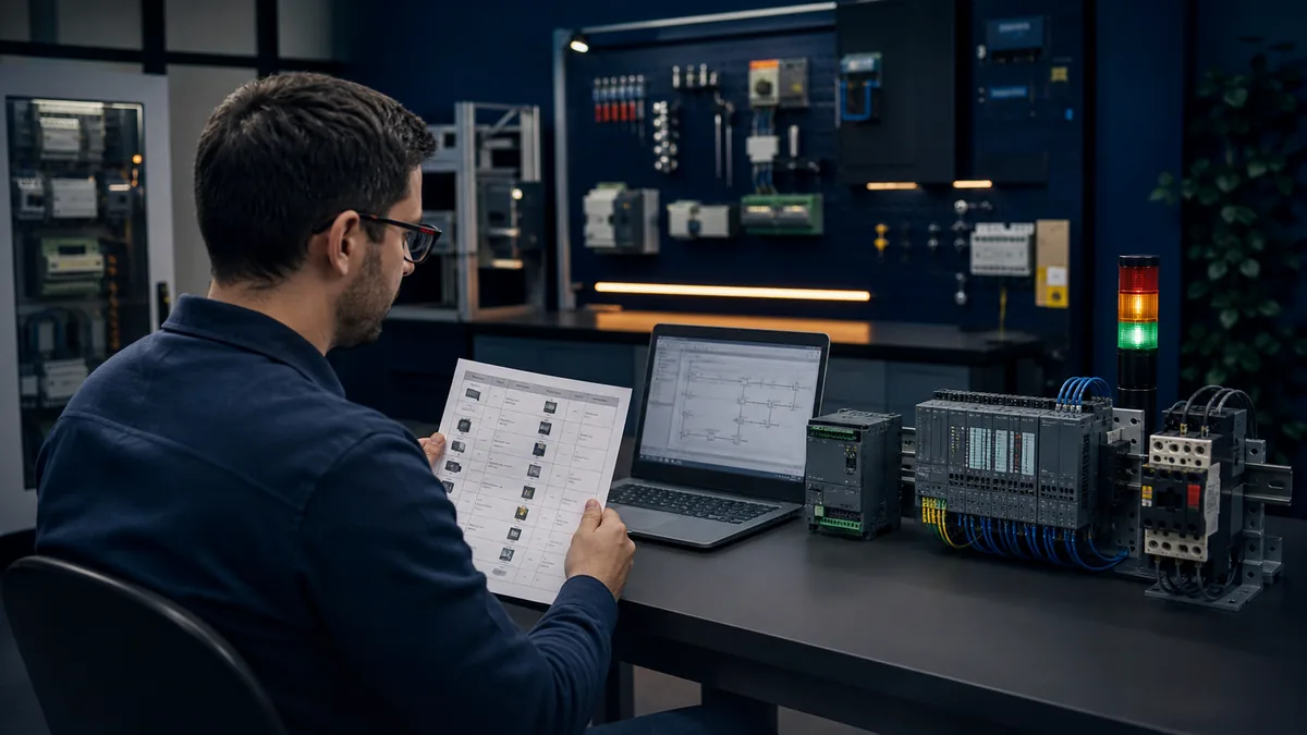
| Layer | Owns | Must not silently own |
|---|---|---|
| input mapping | address, raw state, inversion, scaling, range/quality | sequence state or HMI command authority |
| equipment FB | request, permit, command, feedback, state and diagnostics for one equipment type | raw address scattered inside each instance |
| sequence | step/state and transitions between equipment actions | direct physical output writes |
| mode/command arbitration | local/remote, manual/auto and command ownership | bypasses around equipment permits |
| alarm/diagnostics | first-failed condition, timeout, status and acknowledged lifecycle | control state used only for display convenience |
| output mapping | final application command to approved physical output | additional hidden sequence logic |
Siemens' programming guideline for S7-1200/S7-1500 discusses structured, reusable programming, symbolic access and optimized blocks. Apply recommendations in the context of the exact controller, TIA release, connected systems and migration constraints; an existing non-optimized interface may be a deliberate compatibility contract.
Test one motor or valve object as a behavior contract
The earlier SCL fragment illustrates command state, but a complete test contract should distinguish request, start eligibility, command, feedback, timeout, trip, reset and restart. Use a generic learning object first, then implement it using the exact supported instructions and project structure.
| Case | Initial state | Event | Expected command | Expected diagnostic/state |
|---|---|---|---|---|
| normal start | stopped, permits healthy | accepted start | on | starting, then running on feedback |
| denied start | stopped, one permit false | start | off | named first failed permit |
| feedback timeout | command on, feedback false | timeout expires | project-defined safe result | start-failed trip with elapsed evidence |
| running trip | running | overload/process trip | off | latched or active cause per requirement |
| reset denied | trip cause still active | reset | off | reset rejected with cause |
| restart | declared retained/nonretained state | CPU restart | matches approved restart policy | no accidental automatic action |
Do not use a generic motor FB as safety logic. A fail-safe application requires the correct F-CPU/F-I/O where selected, approved instructions/devices, risk-based architecture, access control, verification and validation. Standard logic may expose status and coordinate operation without replacing the protective function.
Use PLCSIM for supported behavior, then hand off the missing layers
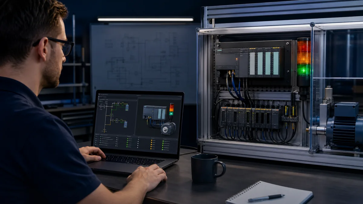
PLCSIM can test supported CPU/application behavior, but exact scope depends on the selected CPU, TIA Portal and simulator edition/version. Confirm current Siemens documentation rather than assuming every module, network peer, technology object or timing path is simulated.
| PLCSIM test | Record | Later handoff |
|---|---|---|
| normal/abnormal sequence | initial state, event timeline, states, commands and result | actual device/process response |
| timer/counter/edge | task context, inputs and observed instruction state | physical event rate and I/O timing |
| restart/retention | simulated restart type and stored state | exact powered-controller cold/warm/restart behavior |
| diagnostic branches | injected conditions and first-cause result | real module/device diagnostic records |
| HMI/tag contract where supported | tag, type, units, access and state change | deployed HMI connection and user/authority tests |
| communications stub | simulated interface data and stale/bad cases | actual partner identity, mapping, load and reconnect |
Practice the same state and fault reasoning in a browser simulator when you need a fast learning loop before a TIA project. It is a disclosed learning environment, not Siemens STEP 7, TIA Portal or PLCSIM. It does not validate an S7-1200/G2 project, instruction implementation, CPU, firmware, I/O, network, machine, process or safety function.
Download the S7-1200 simulation-to-commissioning handoff so every simulated pass has a named remaining field test.
Download and commission as a controlled change
Before connecting, verify authorization, maintenance window, asset identity, current operating state, project provenance, accessible-device identity and rollback. Comparing the target and offline configuration is evidence; discovering “a PLC at this IP” is not enough.
Commission in evidence order:
- confirm CPU/module/network identity and diagnostics;
- verify the running project/version and expected operating mode;
- reconcile each input from known field condition to channel and application tag;
- test output channels under the approved commissioning method with final elements controlled;
- prove mode and command ownership;
- run normal sequence cases;
- inject permitted abnormal, timeout and communication-loss cases;
- verify restart and retained-state behavior;
- remove every force/test override and independently review the force table;
- archive the commissioned project, manifest, comparisons, test results and open issues.
Cybersecurity and production constraints matter. NIST SP 800-82 Rev. 3 frames OT security around performance, reliability and safety. Engineering access, accounts, remote paths, software/media sources, backups and changes should follow the asset owner's controls. Do not normalize connecting an unmanaged learning laptop to an operational PROFINET network.
Diagnose S7-1200 faults by the first failed boundary
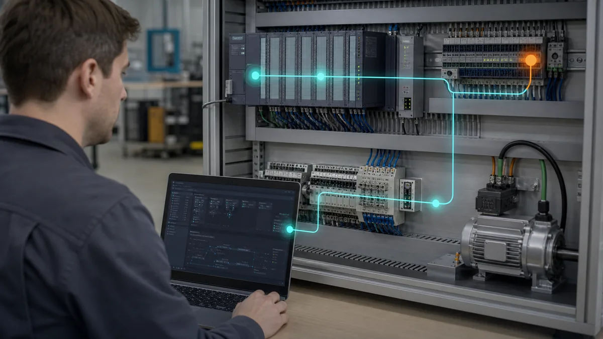
Use CPU LEDs and device overview to orient, then preserve the diagnostic buffer/event detail, timestamp and affected component. Compare online/offline hardware and blocks before assuming logic changed. Trace the failing requirement through field condition, module/channel, application tag, program condition, output command, output electronics/device and independent feedback.
| Boundary | Evidence | Do not jump to |
|---|---|---|
| power/CPU | supply, LEDs, operating state and diagnostic buffer | project download |
| identity/configuration | article/firmware, online/offline compare and module status | swapping a similar module |
| input | known condition, channel LED/status, raw tag and mapped tag | forcing internal logic |
| program | current state, first false condition, task/block execution | rewriting the sequence |
| command/output | command owner, output tag, channel and field supply | assuming output true means actuator moved |
| device/process | drive/contactor/valve status and independent feedback | clearing alarms without cause |
Download the S7-1200 first-fault evidence worksheet. Capture evidence before clearing, power cycling, downloading or replacing a component when the authorized recovery procedure permits.
Frequently asked questions
What is a Siemens S7-1200 PLC?
It is Siemens' compact SIMATIC controller family engineered with STEP 7 in TIA Portal. The name now spans the established S7-1200 and S7-1200 G2 generation, so the exact article number, firmware and generation must accompany any capability or compatibility claim.
Is S7-1200 G2 compatible with the earlier S7-1200 hardware?
Do not assume it is. Siemens explicitly states that S7-1200 G2 modules are not hardware-compatible with the previous generation. Treat a G2 migration as an engineered hardware, software and validation change.
Which software programs an S7-1200?
STEP 7 within Siemens TIA Portal is the engineering environment. The required version/edition and available features depend on the exact CPU, firmware and project. Verify current compatibility and licensing with Siemens before purchase or migration.
How do I choose an S7-1200 CPU?
Start with I/O, execution, memory/data, high-speed/motion, communication, safety, lifecycle and environmental requirements. Then match the current Siemens selection data and manuals. A point count alone is not a defensible CPU decision.
How should I structure an S7-1200 project?
Keep OB coordination readable, encapsulate stateful equipment in FBs with instance data, use FCs for suitable stateless transformations, define DB interfaces deliberately and isolate physical I/O mapping from application behavior.
Should I use optimized data blocks?
Use the option that fits the exact CPU, TIA release, access clients and migration contract. Optimized access is normal in modern S7-1200 design, but an existing absolute/non-optimized interface may be required by a documented consumer. Test the complete interface.
Can PLCSIM simulate an S7-1200?
Supported S7-1200 application behavior can be tested with the appropriate Siemens simulation product, but CPU, module, communication, technology and timing coverage varies. Record the exact versions and list every layer that still needs target or field proof.
Can a browser PLC simulator replace PLCSIM?
No. A browser lab can teach logic, state and troubleshooting in its disclosed dialect. It does not compile or validate an S7-1200 project and cannot prove Siemens instruction, CPU, firmware, I/O or network behavior.
How do I connect to an S7-1200 in TIA Portal?
Use the approved engineering interface and network plan, select the correct PG/PC adapter, find accessible devices, and verify MAC/IP, PROFINET name, order number and project identity before any change. Do not identify a production asset by IP alone.
Why does an input LED turn on while my program tag stays false?
Check the configured module/channel address, online module status, raw tag, mapping logic and any inversion or quality handling. The first disagreement between channel and application tag usually localizes the issue.
Why is an S7-1200 output tag true but the device remains off?
Trace the configured output channel, module LED/status, load supply/common, terminal, relay/contactor/drive and independent feedback under the authorized electrical procedure. A command bit does not prove field energy or motion.
What should I test after downloading an S7-1200 project?
Verify identity and diagnostics, I/O, mode/command ownership, normal sequence, denied starts, trips/timeouts, communication loss where applicable, restart/retention, removed forces/overrides and the final archived version.
Does an S7-1200 support OPC UA, PROFINET, IO-Link, CANopen or EtherCAT?
PROFINET is integral to the family, while other roles depend on the exact CPU/generation/firmware, licences, modules, masters or gateways. Use the protocol-specific guides and current Siemens/device documentation; do not transfer one model's claim to all S7-1200s.
Can standard S7-1200 logic implement a machine safety function?
Do not treat ordinary application logic as a universal safety solution. Required risk reduction needs the selected fail-safe architecture, approved hardware/software, competent engineering and lifecycle validation under applicable standards and local rules.
Primary references
- Siemens, S7-1200 G2 programmable controller system manual, V1.0.1, April 2025.
- Siemens, S7-1200 G2 system-manual product update, August 2025.
- Siemens, established S7-1200 system manual.
- Siemens, S7-1200 Easy Book.
- Siemens, programming guideline for S7-1200 and S7-1500.
- Siemens, SIMATIC controller configuration and selection.
- Siemens, S7-1200 G2 compared with S7-1200 and S7-1500 in TIA Portal V21.
- Siemens, TIA Portal documentation landing page.
- Siemens, SIMATIC S7-PLCSIM product information.
- Siemens, S7-1200 OPC UA server configuration in TIA Portal V21.
- Siemens, S7-1200 G2 PROFINET system description.
- Siemens, Industry Online Support.
- Siemens, SCE learning and training documents.
- Siemens, SITRAIN learning catalog.
- IEC 61131-3:2025 Edition 4 public scope.
- IEC 62443 series overview.
- NIST SP 800-82 Rev. 3—Guide to OT Security.
- OSHA 29 CFR 1910.147—Control of hazardous energy.
- PROFINET University: PROFINET system description.
Use Siemens Industry Online Support to recheck current manuals, firmware, TIA compatibility, product information and security advisories for the exact article number at the time of work.
Continue learning
Now run it · free to start
Practise Siemens-style PLC logic in your browser
Build and run Siemens-style ladder and SCL without a TIA Portal install. An independent learning tool — free to start.
Ownership disclosure: PLC Programming IO and PLC Simulation Software are operated by the same publisher.