S7-1200 PROFINET: TIA Portal Setup and Diagnostics
Configure S7-1200 PROFINET in TIA Portal: verify the CPU and role, plan identity, add IO devices, map data, commission safely and diagnose faults.
Review status: Editorially reviewed against current Siemens S7-1200 V20 and S7-1200 G2 V20 documentation, current PROFINET with STEP 7 guidance, PI design and commissioning guidance and NIST OT security guidance; exact CPU, hardware, firmware, TIA version, device, GSD, topology, timing and security design remain project-specific
Direct answer
To configure S7-1200 PROFINET, first record the exact CPU order number, hardware generation, firmware and TIA Portal version. Decide which communication relationship you actually need: the S7-1200 as a PROFINET IO Controller for remote I/O or drives, as a supported PROFINET I-Device below another controller, or merely as an Ethernet endpoint for HMI, S7 communication, PUT/GET or open TCP/UDP. Those services can use the same physical interface but they are not interchangeable.
For a normal IO Controller project, place the exact S7-1200 CPU and exact IO Device in TIA Portal, connect their PROFINET interfaces to the same configured IO system, use an integrated catalog object or a manufacturer-controlled compatible GSDML/GSDX, build the device's real slot/subslot layout, assign a unique project device name and IP plan, download the controller configuration, then assign the configured PROFINET name to the intended physical MAC address. Confirm that the controller reports cyclic data exchange before validating mapped inputs, outputs, diagnostics, loss behavior and recovery.
Do not begin with ping. A successful ping proves a limited IP path; it does not prove that the configured device name, vendor/device identity, module layout, application relationship, update behavior or PLC mapping matches. Conversely, PROFINET commissioning can use local discovery and name assignment before an ordinary routed IP test is useful. Preserve the native controller and device diagnostics instead of resetting or renaming equipment at random.
This page owns the S7-1200-specific PROFINET implementation task. Use the PROFINET PLC guide for vendor-neutral protocol roles, real-time classes, GSDML, topology and MRP. Use the ET 200 PROFINET guide for ET 200SP rack, BaseUnit and interface-module details. Use the S7 family guide to select an established S7-1200, S7-1200 G2 or S7-1500. No example here overrides the current manual for an exact CPU and connected device.
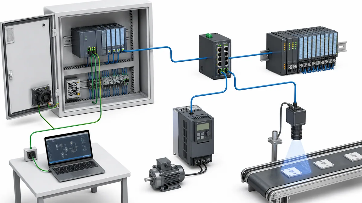
Choose the correct owner, role and communication service
| Engineering task | Correct relationship | Content boundary |
|---|---|---|
| Control ET 200SP, a PROFINET drive or third-party PROFINET device | S7-1200 as IO Controller; field unit as IO Device | this guide plus exact CPU/device manuals |
| Expose one S7-1200 as cyclic I/O below a higher controller | supported S7-1200 as I-Device with defined transfer areas | verify CPU/firmware/TIA support and loss behavior |
| Exchange application data between two PLCs | choose I-Device, S7 connection, OUC or another documented service from requirements | “both ports say PROFINET” does not select the application protocol |
| Connect an HMI | supported HMI-to-PLC connection over the CPU interface | HMI tags and security are not PROFINET IO slots |
| Send custom TCP or UDP messages | open user communication with documented instructions and connection parameters | non-cyclic messaging is not a substitute for IO Device configuration |
| Learn generic PROFINET timing, conformance or cabling | PROFINET PLC guide and PI documents | avoid duplicating the protocol owner |
| Configure ET 200SP modules and BaseUnits | ET 200 PROFINET guide | rack electrical construction belongs to the device owner |
Treat S7-1200 generations as separate compatibility rows
“S7-1200” does not identify one fixed communications platform. The established S7-1200 line and S7-1200 G2 have separate current manual collections. CPU variants, interface port counts, supported PROFINET functions, resource limits, timing capabilities, security features and minimum engineering versions can differ. A sample for one CPU 1215C, firmware and TIA release is not a specification for every CPU 1211C through 1217C or for G2.
Create a compatibility record before engineering:
| Field | Evidence to preserve | Why it changes the result |
|---|---|---|
| Full CPU order number and hardware generation | label, project catalog identity and online device identity | selects the correct manual and interface capabilities |
| Installed and configured firmware | online diagnostics and device configuration | features and diagnostics can change by firmware |
| TIA Portal/STEP 7 version and update | installed product evidence and project record | determines catalog, GSD and CPU support |
| Required role | IO Controller, I-Device, HMI/S7 endpoint or OUC endpoint | roles use different configuration and failure semantics |
| Connected device identity | manufacturer, order number, hardware/firmware and GSD source | prevents a visually similar device from inheriting the wrong layout |
| Required timing and availability | process requirement, update/watchdog design and recovery objective | rules out unsupported assumptions before commissioning |
| Security zone and access path | approved network design, users, certificates and change process | the engineering interface is part of the OT attack surface |
Plan identity and topology before opening TIA Portal
Give every object one unambiguous identity
PROFINET engineers work with several identities at once. Mixing them is a common reason that a device is reachable yet remains unavailable to the IO Controller.
| Identity | Where it comes from | What it proves | What it does not prove |
|---|---|---|---|
| Order number and device identity | label, electronic identity and GSD/catalog object | expected product and module model | that the physical unit has the configured name |
| MAC address | manufacturer-assigned interface identity | which local physical interface was discovered | the intended project role or slot layout |
| PROFINET device name | configured project and persistent device assignment | stable IO Device identity used during startup | that IP routing, modules or field wiring are correct |
| IP address/subnet | project/controller or documented device assignment method | applicable IP reachability and services | cyclic PROFINET configuration or application relationship |
| Station/PLC name in TIA | engineering-project object | human-readable project organization | the exact on-wire PROFINET name unless configured accordingly |
| Slot/subslot and I/O address | GSD/catalog configuration and project mapping | location of cyclic process and diagnostic data | electrical terminal behavior or safe state |
Use a controlled naming convention tied to plant area and function, but comply with PROFINET naming rules and the engineering tool's conversion behavior. Check for duplicates before assignment. When discovering devices, correlate MAC, label, switch port, physical flash/identify function where supported, and cabinet drawing. Writing a plausible name to the wrong unit can create a second outage.
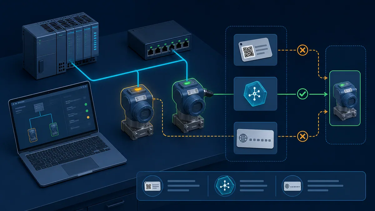
Design the physical network and access path
Record the controller interface and ports, every IO Device, switches, uplinks, trunks, rings, engineering connection, HMI/SCADA peers, security-zone boundary, cable route and power source. Use the current PI design/installation guidance plus each manufacturer's cable, connector, grounding, shielding, spacing and environmental instructions. An RJ45 connector does not by itself establish industrial suitability.
Separate availability claims. A dual-port device in a line does not create redundant control. MRP can recover a supported ring media path when every participant and role is correctly designed, but it does not duplicate the CPU, IO interface, field supply, output circuit, actuator or safety function. Treat controller redundancy, media redundancy, device redundancy, power redundancy and functional safety as different requirements.
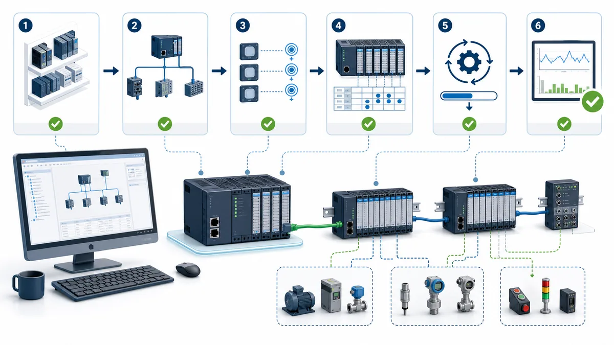
Configure S7-1200 PROFINET in TIA Portal
Build a version-controlled project baseline
- Back up and compare the running project under the site's approved change procedure.
- Add or verify the exact S7-1200 CPU order number, firmware and interface in Device view.
- Configure the CPU's PROFINET interface according to the approved IP, subnet, name, time and access design.
- Add the exact IO Device from the supported integrated catalog or import its manufacturer-controlled compatible GSDML/GSDX.
- Build the device's actual modules, slots, subslots and parameters in their real physical order.
- Connect the green PROFINET interfaces in Network view and assign the IO Device to the intended S7-1200 IO Controller.
- Review generated input/output addresses, process image, consistency, diagnostics, update time and watchdog behavior.
- Compile hardware and software; resolve identity, device-version, module, address and security warnings.
- Download only through the authorized change window and preserve the before/after online comparison.
- Assign the configured device name to the verified physical device, then confirm controller/device data exchange and run acceptance tests.
Do not force the physical rack to match an accidental project by moving modules or changing addresses without design review. The project is not authoritative merely because it compiles; the field assembly is not authoritative merely because it powers up. The acceptance baseline is the approved design reconciled to both.
Use the right device description
An integrated TIA Portal catalog object is appropriate when it exactly matches the device, modules and firmware behavior required by the project. Otherwise obtain the current supported GSDML/GSDX or prescribed hardware support package from the manufacturer. Preserve source URL, filename, version/date, checksum where available, import result and project compatibility.
GSDML describes identification, device structure, communication features, process data, parameters and diagnostics. It does not certify the field wiring, drive telegram choice, engineering units, substitute values or machine response. A newer file is not automatically safe for an older approved project, and a file from an unofficial download mirror is not a controlled dependency.
Map cyclic data as a contract
For each slot/subslot or telegram, record the physical signal, configured module, controller address/tag, data type, byte order where relevant, engineering unit, valid range, quality/diagnostic relationship, consumer logic, substitute behavior and acceptance result. Avoid treating an array of bytes as self-documenting.
| Contract field | Positive test | Negative or loss test |
|---|---|---|
| Device and module identity | configured and actual identities match | wrong or missing module produces the expected diagnostic |
| Input mapping | known field state reaches the intended tag | open circuit/device diagnostic does not masquerade as a valid value |
| Output mapping | approved command reaches the intended channel and load | controller/device/network loss produces the designed state |
| Analog/telegram scaling | several traceable test points meet tolerance | out-of-range and bad-quality behavior is handled explicitly |
| Update/watchdog behavior | measured response meets the process requirement | delayed/lost data is detected inside the required time |
| Recovery | controlled restore returns to the approved operating sequence | no unexpected restart, stale command or retained hazard appears |
Live mini-lab
Try it: press START, then STOP
A stop-dominant seal-in rung: START latches the motor output through its own contact, and STOP breaks the circuit.
Watch the output lamp: it stays on after START until you press STOP.
Free to start · runs in your browserOpens plcsimulationsoftware.com — same team
Separate PROFINET IO from other S7-1200 Ethernet communication
One interface can carry different services
Technicians often say two PLCs “communicate over PROFINET” because the cable is connected to the PROFINET-labeled interface. That description is incomplete. Cyclic PROFINET IO, S7 communication, HMI connections and open user communication have different engineering objects, data contracts, timing, access controls, diagnostics and failure behavior.
| Service | Typical use | Configuration evidence | Do not call it |
|---|---|---|---|
| PROFINET IO | cyclic controller-to-device process data and diagnostics | IO system, controller/device roles, slots/subslots and update behavior | generic TCP polling |
| PROFINET I-Device | one supported CPU exposes transfer areas as an IO Device | operating mode, assigned controller, transfer areas and GSD when crossing projects | an unrestricted “slave PLC” |
| S7 connection / PUT-GET where supported and enabled | controller-to-controller data access | connection resource, endpoints, DB/access settings and security decision | PROFINET IO mapping |
| HMI connection | operator interface tags, alarms and commands | HMI/PLC connection, users/access and tag contract | an IO Device slot model |
| Open user communication | application-defined TCP, ISO-on-TCP or UDP behavior | TSEND/TRCV family, connection parameters, framing, timeout and security design | deterministic cyclic IO |
The generated illustration below is an explanatory separation, not a timing guarantee. Controller-to-controller traffic is not inherently event-driven, and open messaging is not inherently safe for analytics; actual behavior comes from the configured service and application.
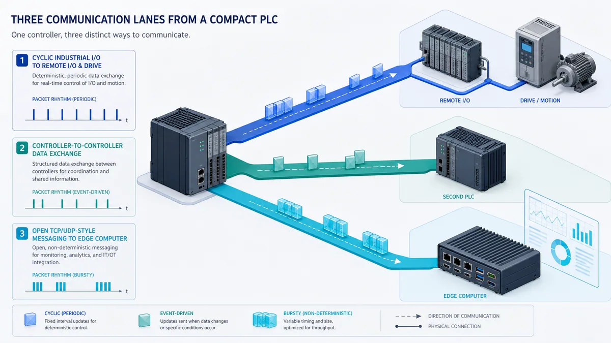
Configure an S7-1200 as an I-Device only from supported evidence
Current S7-1200 V20 documentation includes I-Device configuration and transfer areas for supported CPUs. Enable the IO-Device operating mode on the intended interface, assign the higher-level IO Controller, decide whether interface parameters are supplied locally or by that controller as documented, and define transfer areas with explicit direction, length, consistency and user-program ownership.
Test both sides of a network loss. Siemens documents that controller and I-Device transfer-area behavior can differ: for one documented input-transfer case the controller writes zero on loss while the I-Device retains its last value. The application must not infer “safe,” “fresh” or “invalid” from a value alone. Add status, heartbeat, sequence, timeout and state-machine handling appropriate to the process.
When the I-Device is engineered in another project/system, preserve the exported GSD and transfer-area contract as controlled interface artifacts. A changed transfer length or direction is an interface revision, not a harmless tag edit.
Diagnose S7-1200 PROFINET faults in evidence order
Capture before changing
Record incident time, machine symptom, CPU mode and LEDs, active/stored diagnostics, accessible-device identity, project online comparison, switch port/link counters, configured/actual module state, affected I/O quality, recent changes and control-power events. Synchronize clocks well enough to correlate evidence. Do not clear diagnostics, reassign names, factory-reset devices or download a project until the original state has been preserved and the action is authorized.
Use the first failed boundary:
| Symptom | First evidence | Likely boundary | Avoid as first action |
|---|---|---|---|
| CPU and every device absent | CPU/interface supply, LEDs, cable, switch port and engineering path | power, media or access path | changing all IP addresses |
| one device absent from accessible devices | device supply, port, cable and local discovery | physical device or segment | editing PLC logic |
| device discovered but not in data exchange | configured/actual name, identity and controller PNIO diagnostics | PROFINET identity/configuration | repeated ping tests |
| station online with module fault | slot/subslot comparison, GSD/catalog and module diagnostics | wrong/missing module or parameter | shifting I/O addresses blindly |
| inputs update but outputs do not act | command, permissives, output quality, channel LED, terminal measurement and load power | application, mapping, output circuit or field device | forcing a live-machine output |
| intermittent dropouts | timestamped diagnostics, port counter deltas, topology and control-power trace | media, connector, EMC, load or recovery timing | replacing random modules |
| second PLC receives stale data | exact service status, heartbeat/sequence, connection state and timeout logic | application communication contract | calling the link “PROFINET” and stopping there |
| replacement device will not start | article/firmware, name, supported device description and topology replacement settings | compatibility or identity | copying the old IP only |
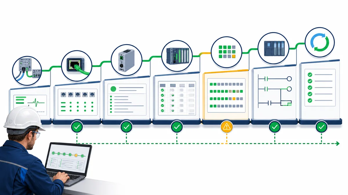
Interpret ping, LEDs and TIA diagnostics correctly
Ping is one IP-layer observation. Link LEDs prove a physical link indication, not cable margin or cyclic exchange. A green CPU does not prove every IO Device is healthy. A green IO Device does not prove every channel, field supply, telegram, scaling or machine response is correct. Read the exact LED table in the CPU/device manual and pair it with TIA Portal online diagnostics and switch evidence.
In TIA Portal, compare configured and accessible identities, inspect the CPU diagnostic buffer, PROFINET interface, distributed-I/O overview, module/channel status and topology where configured. Preserve event identifiers and detailed text with timestamps. If a GSD device reports a generic diagnostic, use its current manufacturer manual to decode the channel and extended information.
Commission with positive, negative and recovery tests
Use a handover-grade acceptance matrix
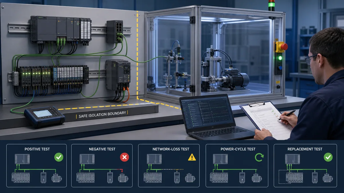
At minimum, test exact identity, online configuration, every required input and output, analog/telegram boundaries, bad quality, device loss, link restoration, power cycle, controller mode transition, approved replacement behavior, alarm visibility and application recovery. Add drive-safe-state, motion, process, functional-safety and cybersecurity tests from the machine risk assessment and validation plan; PROFINET communication alone never proves those claims.
| Test case | Controlled stimulus | Expected evidence | Acceptance record |
|---|---|---|---|
| Identity | discover and identify each node | project name maps to the intended MAC/order number | device list and physical correlation |
| Cyclic positive | apply known sensor/command cases | correct slot/tag/value/quality and physical result | measured values and timestamps |
| Negative mapping | disconnect or simulate approved missing/bad input | expected channel/device diagnostic and application response | diagnostic ID and state transition |
| Network loss | interrupt one approved path | watchdog/loss detected; outputs and logic follow design | measured detection and recovery times |
| Power cycle | cycle approved device/control power | deterministic startup with no unintended action | sequence, diagnostics and final state |
| Replacement | use approved spare/process | identity assignment and configuration recover correctly | article/firmware/name and regression result |
| Load/recovery | exercise representative traffic and restart | process deadlines and connection recovery meet requirements | max/observed times and deviations |
Secure engineering and maintenance access
Segment the control network according to the OT architecture, restrict engineering paths, use supported authenticated mechanisms, control project/GSD/firmware provenance, back up the recoverable configuration and log changes. Avoid exposing a PLC interface directly to untrusted networks. If legacy or convenience communication requires relaxed access, record the risk decision, compensating controls and retirement plan rather than treating a successful connection as approval.
The industrial communication training path can help technicians rehearse controller/device roles, identity, layered diagnosis and recovery reasoning. It does not emulate S7-1200 firmware, TIA Portal, Siemens security, PROFINET timing, GSD behavior, installed wiring, a drive telegram or a safety function. Validate the real project and plant separately.
Diagnostic answer map
| Natural-language query | Concise answer | Evidence to capture |
|---|---|---|
| How do I configure S7-1200 PROFINET? | Add exact CPU/device objects, connect one IO system, map real modules, assign the configured device name to the verified unit, download and test cyclic data. | order numbers, firmware, TIA/GSD, name/MAC, module comparison and acceptance matrix |
| Why can I ping a device but S7-1200 still reports an IO fault? | Ping does not prove PROFINET name, identity, module layout or application relationship. | controller PNIO diagnosis and configured-versus-actual identity |
| Is the S7-1200 a PROFINET controller or device? | It normally controls IO Devices; supported CPUs can also be configured as I-Devices for defined transfer areas. | exact CPU/firmware/TIA role support |
| How do two S7-1200 PLCs communicate? | Select I-Device, S7 communication or OUC from the required data, timing, security and loss semantics. | service, endpoints, data contract, status and recovery tests |
| Does an S7-1200 need a PROFINET name and IP address? | The CPU and IO Devices use documented identity/address configuration; IO Device startup relies on the configured device-name relationship, not IP alone. | project names/IP plan and read-back physical assignment |
| How do I add ET 200SP to S7-1200? | Add the exact ET 200SP interface/modules, assign it to the CPU's IO system, name the physical interface and validate rack/channel behavior. | ET 200 articles, BaseUnits, name/MAC and I/O tests |
| Why does S7-1200 show module difference? | The configured slot/subslot, article, version or parameters differ from the actual device. | online comparison, GSD/catalog version and physical order |
| Can I use PUT/GET and call it PROFINET communication? | It can traverse the CPU's Ethernet interface but is S7 communication, not cyclic PROFINET IO. | connection/access configuration and explicit security decision |
| Does MRP make an S7-1200 system redundant? | It can protect a supported media ring; it does not duplicate controller, device, power, field circuit or safety function. | supported roles/topology and measured recovery behavior |
| Can a browser simulator validate S7-1200 PROFINET? | It can train diagnostic reasoning, not certify hardware, firmware, GSD, timing, wiring or safety. | approved TIA project, official manuals and plant tests |
Frequently asked questions
Does the Siemens S7-1200 support PROFINET?
Yes, S7-1200 CPUs provide documented PROFINET/Ethernet communication capabilities, but functions and limits depend on the exact established or G2 CPU, firmware and TIA Portal version. Verify the required IO Controller, I-Device, topology, timing and security features in that CPU's current manual.
How do I configure PROFINET on an S7-1200 in TIA Portal?
Configure the exact CPU interface, add the exact IO Device, connect it to the CPU's PROFINET IO system, build its modules, review addresses/timing, compile and download, then assign the configured device name to the verified physical unit and run I/O and recovery tests.
Is a PROFINET device name the same as an IP address?
No. The name is the configured PROFINET IO Device identity used in controller startup and assignment; IP supports applicable IP communication. A correct IP or successful ping does not prove the name, device identity or cyclic configuration matches.
Can an S7-1200 operate as a PROFINET IO Device or slave?
Supported S7-1200 combinations can use I-Device functionality, which exposes defined transfer areas to a higher-level IO Controller. Do not rely on the generic word “slave”; verify CPU, firmware, TIA support, transfer direction and network-loss behavior.
How can two S7-1200 PLCs communicate over the same Ethernet network?
Choose a documented application service—such as I-Device, an S7 connection or open user communication—from the required cyclicity, data ownership, consistency, status, security and recovery behavior. The shared physical interface does not make those methods equivalent.
How do I connect ET 200SP remote IO to an S7-1200?
Add the exact ET 200SP PROFINET interface and module order, assign the station to the S7-1200 IO Controller, configure name/IP and modules, then validate interface power, device identity, cyclic status, every required channel and loss/recovery behavior.
Do I need a GSDML file for an S7-1200 PROFINET device?
Use an integrated TIA Portal catalog entry when it exactly supports the device. Otherwise obtain the current compatible GSDML/GSDX or prescribed support package from the device manufacturer and preserve its source and version. Never use a random mirror as a production dependency.
Why is my PROFINET device visible but not exchanging data?
Local discovery proves the device is visible on that segment. The project name, assigned physical name, order/device identity, modules/submodules, parameters, controller assignment or firmware/GSD support can still differ. Read the S7-1200's PROFINET and module diagnostics.
Does S7-1200 PROFINET support MRP or IRT?
Support is combination-specific and differs across established S7-1200 and G2 CPUs, firmware, ports, devices and engineering versions. Build a compatibility row from current manuals; do not copy a capability or limit from another CPU or a generic PROFINET article.
How should an S7-1200 PROFINET network be acceptance-tested?
Test identity, configured-versus-actual hardware, cyclic input/output mapping, quality and diagnostics, update/watchdog behavior, device and link loss, power cycle, approved replacement, application safe/substitute states and recovery. Record measured evidence, not only green LEDs.
Sources, review scope, and limitations
This guide was reviewed on August 30, 2026 against the direct Siemens, PI and NIST sources below. Siemens documentation is versioned and Product Information may supersede a manual. Exact order numbers, hardware/firmware, TIA updates, port functions, device counts, timing, topology roles, GSD support, security and failure behavior must be verified for the installed combination. The six illustrations are original product-neutral training graphics, not Siemens product renders, TIA screenshots or wiring drawings.
- S7-1200 Programmable Controller Manual Collection V20 — Siemens — current established S7-1200 configuration, communication, security and diagnostic documentation.
- S7-1200 G2 PROFINET Manual Collection V20 — Siemens — separate current G2 PROFINET capability and configuration tree.
- Configuring an S7-1200 CPU and PROFINET IO Device — Siemens — adding, assigning and configuring a controller/device relationship.
- Configuring an S7-1200 CPU and PROFINET I-Device — Siemens — supported I-Device role and transfer-area configuration.
- Configuring an IP address for an S7-1200 CPU — Siemens — interface, addressing and port behavior.
- S7-1200 distributed I/O and diagnostic instruction context — Siemens — current documentation tree for PROFINET configuration, shared device, MRP and diagnostics.
- PROFINET with STEP 7 Function Manual, 11/2025 — Siemens — controller/device engineering, topology, diagnostics and supported PROFINET functions.
- PROFINET technology overview — PROFIBUS & PROFINET International — official controller/device, cyclic-data and ecosystem context.
- PROFINET Design Guideline V1.59 — PI — current design, naming, GSD and network-planning guidance.
- PROFINET Commissioning Guideline V1.53 — PI — device naming, identity, tests and commissioning evidence.
- GSDML/GSDX Specification for PROFINET — PI — official scope of device identification, structure, process data, parameters and diagnostics.
- PROFINET Installation Guidelines — PI UK — current design, assembly, commissioning and redundancy guide index.
- NIST SP 800-82 Rev. 3 — OT segmentation, access, configuration, monitoring and recovery security context.
Now run it · free to start
Follow plant data from sensor to SCADA
Fieldbus versus Ethernet, Modbus, EtherNet/IP, PROFINET, OPC UA and MQTT, then SCADA layers and alarms, taught on simulated equipment. Free to start.
Ownership disclosure: PLC Programming IO and PLC Simulation Software are operated by the same publisher.
PLC Programming IO Editorial Team
Industrial automation education, references, and software testing
The PLC Programming IO Editorial Team publishes sourced industrial-automation education and documents how material is reviewed, tested, and corrected. A team byline means the publisher is responsible for the page; it does not represent a fictional person or imply an engineering licence.
Coverage:
- • PLC programming concepts and examples
- • Vendor software tutorials and comparisons
- • SCADA, HMI, protocols, and instrumentation
- • Training, careers, and reference material
Review standard:
- • Prefer primary and official sources
- • Record software versions when material
- • Separate tested facts from estimates
- • Publish material corrections
Important scope note
This site provides education, not project-specific engineering approval. Safety, code, and compliance decisions require a qualified person with access to the actual machine and jurisdiction.