S7-1200 EtherCAT: Gateway Setup, Mapping and Diagnostics
Connect an S7-1200 to EtherCAT without pretending its PROFINET port is a native EtherCAT controller: choose the right gateway role, map cyclic data and diagnose both networks.
Review status: Editorially reviewed against current Siemens S7-1200 and S7-1200 G2 documentation, EtherCAT Technology Group references, PI GSDML guidance and current Hilscher and Helmholz gateway documentation; exact CPU, firmware, gateway personality, device descriptions, timing, motion, electrical installation, cybersecurity and safety behavior require project-specific verification
Direct answer: the S7-1200 needs a role-correct EtherCAT integration
A Siemens S7-1200 does not become an EtherCAT MainDevice merely because it has an RJ45 port. Current Siemens technical data describes the established S7-1200 Ethernet interface as a PROFINET IO controller/device interface. The current S7-1200 G2 manual likewise lists PROFINET IO controller and device roles, including IRT, but does not list a native EtherCAT MainDevice role. For an S7-1200 to exchange data with EtherCAT equipment, use an integration whose two protocol roles match the real control requirement.
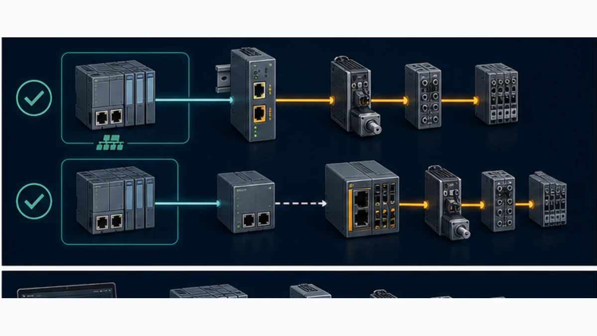
There are two common requirements, and they need different products. If the S7-1200 must own ordinary cyclic I/O on an EtherCAT SubDevice line, a programmable gateway must appear as a PROFINET IO Device to the S7-1200 and operate as an EtherCAT MainDevice on its other network. A current example of a product family that advertises both roles is the Hilscher netTAP NT 151-RE-RE; the exact firmware combination, limits and supported EtherCAT functions still have to be selected and validated.
If an existing EtherCAT controller and the S7-1200 only need to exchange a bounded block of cyclic machine data, use a controller-to-controller coupler. For example, the Helmholz PN/EtherCAT Coupler is documented for data transfer between a PROFINET controller and an EtherCAT master. It is integrated with GSDML on the PROFINET side and ESI on the EtherCAT side. That coupler does not make the S7-1200 the controller of the EtherCAT machine; an independent EtherCAT MainDevice still owns that network.
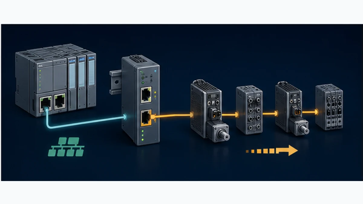
This page owns the S7-1200 compatibility, gateway-selection, TIA Portal mapping and cross-network diagnostic task. Use the EtherCAT PLC guide for frame processing, ESI, PDO, state-machine, Distributed Clocks and Working Counter fundamentals. Use the S7-1200 programming guide for CPU selection, project structure, blocks, simulation and general commissioning. Keeping these owners distinct prevents a gateway procedure from being confused with native support.
Verify the controller capability before choosing hardware
An Ethernet connector is not a protocol role
PROFINET and EtherCAT can both use 100BASE-TX physical media and familiar Ethernet connectors, but they define different frame handling, discovery, configuration, timing and device roles. Moving the same patch cable from one port to another cannot translate between them. A conventional Ethernet switch is not a protocol converter, and a drive's EtherCAT option board cannot teach an S7-1200 to originate EtherCAT frames.
The verification method is deliberately conservative: record the complete S7-1200 order number and generation; open the current Siemens manual or Industry Mall technical data for that exact CPU; inspect the listed protocols and controller/device roles; then record the required field-device protocol, role and features. Absence of EtherCAT MainDevice support from the CPU specification means an external implementation is required. It is more reliable than a reseller page, forum answer or search snippet that equates “Industrial Ethernet” with every Ethernet-based fieldbus.
| Question | Evidence to retain | Stop condition |
|---|---|---|
| Which CPU is installed? | full Siemens article number, hardware generation and firmware | only “S7-1200” is known |
| What role does its port implement? | current CPU manual/technical data naming PROFINET controller or device | capability is inferred from the RJ45 connector |
| What does the other product require? | manual naming EtherCAT MainDevice/SubDevice role, PDOs and synchronization | only a marketing phrase such as “Ethernet drive” is available |
| Who must own the EtherCAT line? | approved architecture and control-responsibility statement | project team cannot name the EtherCAT MainDevice |
| What must cross the boundary? | versioned I/O contract with direction, type, scale, validity and safe behavior | “copy all tags” is the interface specification |
S7-1200 G2 improves PROFINET; it does not erase the boundary
S7-1200 G2 adds stronger motion and communication capability. The current system manual documents PROFINET IRT, isochronous operation and up to 31 PROFINET devices for current CPUs. Siemens' product data explicitly qualifies isochronous mode as “for PROFINET only.” Those improvements may make a direct PROFINET drive architecture more attractive, but they are not evidence of a native EtherCAT stack.
For a new machine, check whether the drive, remote I/O or robot offers an approved PROFINET interface. A direct PROFINET path normally reduces components, configuration artifacts, latency, spare parts and diagnostic boundaries. Use EtherCAT bridging when the EtherCAT equipment, machine ownership, performance evidence or installed base makes it the justified architecture—not because two network names both contain “Ether.”
| Option | Best fit | Principal advantage | Principal limitation |
|---|---|---|---|
| native PROFINET device | selectable drive/I/O interface and S7 owns the device | one controller, one engineering path and direct PROFINET diagnostics | requires a supported PROFINET option and may not match an existing EtherCAT machine |
| PROFINET-device/EtherCAT-MainDevice gateway | S7 must control bounded ordinary I/O on EtherCAT SubDevices | gives the missing initiating EtherCAT role | adds configuration software, latency, feature limits and a second failure domain |
| PN/EtherCAT machine coupler | two existing controllers exchange status/commands | clear machine boundary and bounded cyclic data | S7 does not control the EtherCAT SubDevices |
| separate motion controller | EtherCAT motion/synchronization stays with a qualified platform | preserves native motion features and deterministic ownership | requires a higher-level command/status contract between controllers |
| redesign controller platform | EtherCAT is fundamental to the machine and no bridge satisfies it | removes translation compromise | migration cost, software change and revalidation can be substantial |
Select the integration architecture by roles
Architecture A: S7-owned I/O through an EtherCAT MainDevice gateway
Use this path only when the gateway documentation explicitly supports PROFINET IO Device on the S7-facing port and EtherCAT MainDevice on the field-facing port at the same time. The S7-1200, configured as PROFINET IO Controller, exchanges a fixed cyclic image with the gateway. The gateway separately discovers/configures EtherCAT SubDevices, advances their state machine and exchanges PDOs. Its internal mapping connects selected fields between those images.
Do not select a gateway by the two protocol logos alone. Confirm the exact order number, primary/secondary network placement, loadable firmware personality, simultaneous role combination, maximum I/O bytes, number of EtherCAT SubDevices, minimum cycle, CoE/SoE/FoE needs, Distributed Clocks support, supported operating states, configuration-tool version and diagnostic interface. The Hilscher NT 151 product page lists both PROFINET IO-Device and EtherCAT Master among its supported protocols, while its manual contains role-specific documentation. That establishes a plausible product route, not automatic fitness for a motion or safety application.
Architecture B: controller-to-controller coupler
A coupler exchanges I/O images between two independently controlled machines. On the left, the S7-1200 remains the PROFINET Controller and sees a PROFINET Device described by GSDML. On the right, a separate EtherCAT MainDevice sees an EtherCAT SubDevice described by ESI. Output data received on either side becomes input data on the other according to the configured slots and directions.
Helmholz documents up to 600 bytes in each direction for its current PN/EtherCAT Coupler and provides an additional status byte. Treat those as product-specific reviewed values, not a universal coupler standard. The important architectural fact is that both controllers already exist. If the project has only an S7-1200 and a line of EtherCAT I/O terminals, this coupler class supplies no EtherCAT MainDevice to run that line.
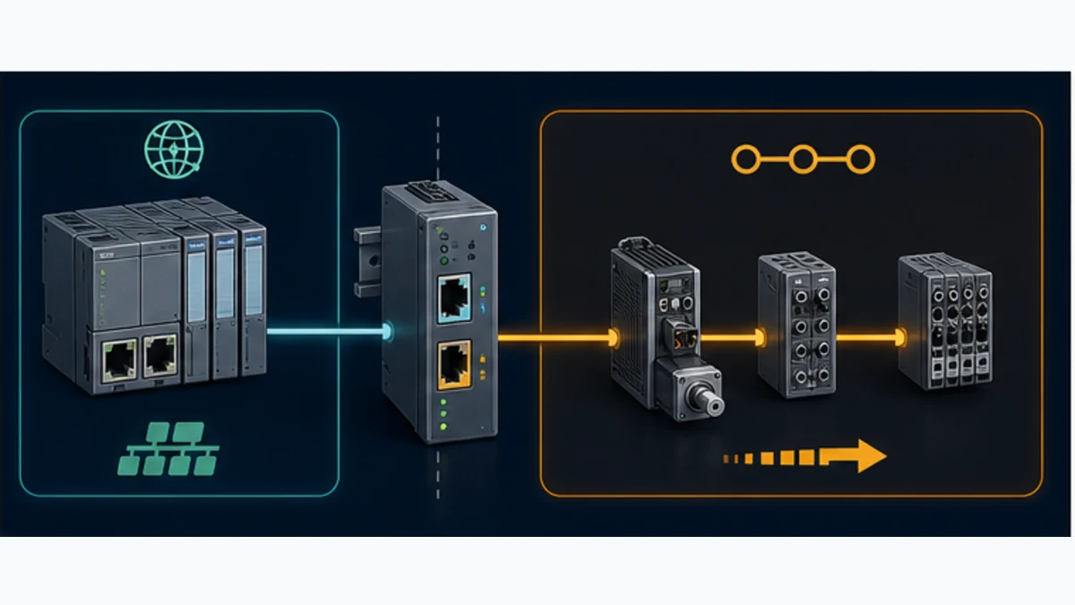
| Required outcome | S7-facing gateway role | EtherCAT-facing gateway role | Suitable pattern |
|---|---|---|---|
| S7 reads/writes ordinary EtherCAT I/O | PROFINET IO Device | EtherCAT MainDevice | active programmable gateway |
| S7 exchanges commands with an EtherCAT-controlled machine | PROFINET IO Device | EtherCAT SubDevice | controller-to-controller coupler |
| EtherCAT machine exchanges data with an S7 acting as a PN I-Device | PROFINET IO Controller or peer path, if product supports it | EtherCAT SubDevice | uncommon role combination; verify both controller projects |
| S7 supervises a separate motion controller | documented PROFINET Device, OPC UA or another approved peer interface | native EtherCAT MainDevice belongs to motion controller | hierarchical controller architecture |
| drive supports native PROFINET and EtherCAT options | none required when PROFINET option is selected | none | direct PROFINET device architecture |
Reject ambiguous product descriptions
“PROFINET to EtherCAT gateway” does not reveal direction or roles. A product may be a PROFINET Controller to EtherCAT SubDevice, the reverse of what an S7-1200 needs. It may only bridge two device roles and therefore require controllers on both sides. It may support EtherCAT SubDevice but not MainDevice. It may load only one protocol at a time. Put the role pair in the purchase specification and require the supplier to identify the exact firmware/configuration combination in writing.
Define the data contract before opening TIA Portal
Map meaning, not just bytes
The protocol boundary should be intentionally small. Start with machine requests, accepted/active states, completion, permissive summary, fault summary, mode, heartbeat, interface version and a few process values. Avoid mirroring a controller's entire DB. A broad unversioned map couples unrelated programs, consumes gateway memory and makes every change risky.
For every field, record producer, consumer, offset, bit/byte order, type, engineering unit, scale, valid range, update expectation, validity rule, stale timeout, startup value and safe response. Multi-byte values need explicit byte order at both sides; a floating-point field needs an agreed IEEE representation or a tested conversion. A Boolean can be packed, but a diagnostic word is often easier to extend than dozens of undocumented bits.
| Offset | S7 name | Direction at S7 | Type | Meaning and acceptance rule |
|---|---|---|---|---|
0.0 |
EC_RequestRun |
output | BOOL | request only; remote controller/device still enforces permissives |
0.1 |
EC_ResetRequest |
output | BOOL pulse | one-shot request with documented acknowledgement behavior |
2 |
EC_CommandSequence |
output | UINT | increments on a new command set; rollover is defined |
4 |
EC_CommandHeartbeat |
output | UINT | changes at an agreed interval while S7 application is healthy |
6 |
EC_InterfaceVersion |
output | UINT | must equal approved contract version before commands are accepted |
8 |
EC_SpeedDemand_x10 |
output | INT | signed engineering value at 0.1 unit resolution and bounded range |
16.0 |
EC_Ready |
input | BOOL | remote application ready, not proof of field safety |
16.1 |
EC_Running |
input | BOOL | remote application state backed by defined feedback |
18 |
EC_StatusSequence |
input | UINT | echoes accepted command sequence or advances with status set |
20 |
EC_StatusHeartbeat |
input | UINT | remote application freshness source |
22 |
EC_FaultCode |
input | WORD | versioned interface fault enumeration; zero means no reported fault |
24 |
EC_ActualSpeed_x10 |
input | INT | remote measured value with validity and scale defined separately |
Carry quality, age and version explicitly
PROFINET may be healthy while EtherCAT is not in OP; EtherCAT may be in OP while the remote application has stopped updating meaningful values. Therefore a single gateway-ready bit is not enough. Carry at least a network/application status word, a changing heartbeat or sequence, an interface version and a data-valid condition. The S7 should calculate age from observed change, not simply trust a value copied through the gateway.
A bounded SCL-style consumer pattern looks like this:
HeartbeatChanged := EC_StatusHeartbeat <> LastStatusHeartbeat;

IF HeartbeatChanged THEN
    LastStatusHeartbeat := EC_StatusHeartbeat;
    StatusAge := T#0ms;
ELSE
    StatusAge := StatusAge + CycleElapsed;
END_IF;

ContractOK := (EC_RemoteVersion = ExpectedVersion);
RemoteFresh := StatusAge <= MaxStatusAge;
RemoteHealthy := PN_DeviceHealthy
              AND GatewayEtherCATOpsHealthy
              AND ContractOK
              AND RemoteFresh
              AND EC_DataValid;

IF NOT RemoteHealthy THEN
    EC_RequestRun := FALSE;
    AcceptedActualSpeed := LastApprovedFallback;
END_IF;
Run Structured Text in the simulator
The exact timers and diagnostic tags depend on the selected devices. The principle is portable: transport health, remote-network health, contract compatibility, freshness and process validity are separate conditions. Preserve the first condition that failed so a later cascade does not erase the origin.
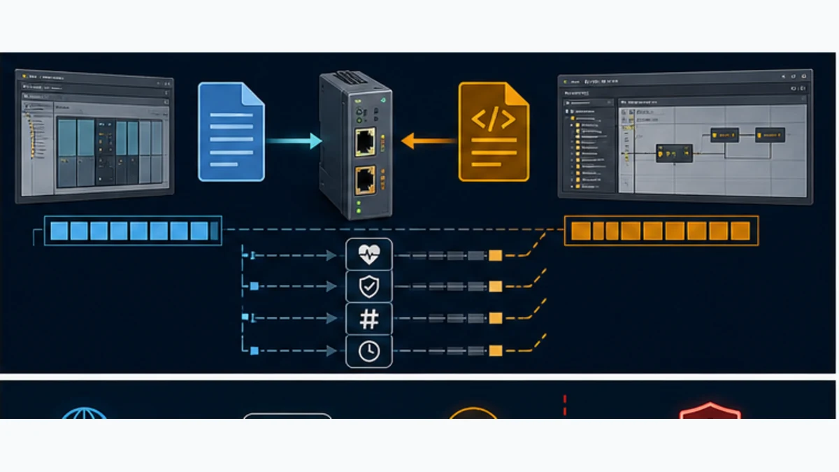
| Contract property | Required decision | Failure prevented |
|---|---|---|
| direction | producer and consumer for every field | both PLCs write or both wait for the same data |
| representation | BOOL packing, integer width/sign, REAL format and byte order | values are connected but numerically wrong |
| engineering meaning | unit, scale, range and invalid marker | raw counts are mistaken for process units |
| freshness | heartbeat/sequence source and maximum age | frozen last-good data remains plausible indefinitely |
| compatibility | interface version and mismatch response | changed map silently shifts every downstream field |
| startup | values before both networks/application are ready | stale or default commands start equipment |
| recovery | acknowledgement and resynchronization sequence | communication return causes an uncontrolled restart |
| safety boundary | safe function implemented outside ordinary map | ordinary network health is treated as a safety channel |
Live mini-lab
Try it: press START, then STOP
A stop-dominant seal-in rung: START latches the motor output through its own contact, and STOP breaks the circuit.
Watch the output lamp: it stays on after START until you press STOP.
Free to start · runs in your browserOpens plcsimulationsoftware.com — same team
Configure the PROFINET side in TIA Portal
Import the exact GSDML and create the device
Obtain the GSDML from the gateway manufacturer for the exact product and firmware. Record the download URL, document version and checksum in the project. In TIA Portal, install the device description, add the precise catalog object to Devices & networks, connect it to the S7-1200 PROFINET subnet and assign an approved PROFINET device name and IP configuration.
GSDML describes a PROFINET Device's identity, modular structure, process data, parameters and diagnostics. It does not configure the EtherCAT SubDevices behind an active gateway. It also does not replace the gateway's own firmware/personality selection. If the catalog object, hardware revision or supported slots do not match, stop rather than forcing a similarly named object.
- Archive the baseline project and export the approved device list.
- Install the current manufacturer GSDML in a controlled engineering environment.
- Add the exact gateway device and connect its PROFINET interface to the correct S7 IO system.
- Assign a standards-compliant device name and reconcile it with the physical unit.
- Build the input/output module layout to match the signed contract.
- Compile hardware and resolve every address, module and consistency warning.
- Map raw process image fields into a dedicated interface DB or typed structure.
- Add module/device diagnostics, startup inhibit, stale-data detection and first-fault capture.
| TIA Portal evidence | Acceptance condition | Common defect |
|---|---|---|
| installed GSDML | exact supplier file/version for installed gateway firmware | old web download or another model's file |
| PROFINET device name | configured name equals commissioned device identity | IP responds but PROFINET device remains unavailable |
| module/slot image | sizes and directions match gateway configuration byte for byte | one inserted byte shifts every following value |
| process addresses | no overlaps; mapped in a single owned layer | raw %I/%Q addresses scattered through logic |
| device diagnostics | S7 reports module/device state and records first loss | only a generic “comm fault” lamp exists |
| restart behavior | commands inhibited until contract, freshness and remote readiness pass | outputs resume because last values returned |
Keep the raw map outside machine logic
Create a dedicated gateway interface block. One routine writes sanitized commands to raw output addresses; another reads raw inputs, applies conversion and updates quality. Application FBs consume meaningful tags such as RemoteMachine.Ready and RemoteMachine.ActualSpeed, not IW256. This isolates device-description changes and makes the contract reviewable.
When data consistency across multiple bytes matters, use the access method and consistency length documented for the S7 CPU and gateway. Do not assume a 32-bit value is coherent if its bytes can be updated across separate cycles. Use a sequence guard, consistent module region or double-read validation as the approved platform requires.
Configure the EtherCAT side
Active MainDevice gateway path
For a gateway that acts as EtherCAT MainDevice, use its supported configuration tool and current manual. Import manufacturer ESI XML for every exact EtherCAT SubDevice/revision, scan or construct the physical order, select PDOs, map them into the gateway image, set startup services, choose a defensible cycle and configure Distributed Clocks only when both gateway and devices support the required mode.
EtherCAT Technology Group describes ESI as the XML file containing a SubDevice's network-accessible properties, process-data mapping choices, mailbox protocols and synchronization modes. Similar marketing names can carry different vendor IDs, product codes, revisions or PDOs. A successful physical scan with “unknown” XML is evidence of a description mismatch, not permission to select the nearest catalog entry.
Controller-to-controller coupler path
For a passive machine coupler, the EtherCAT controller imports the coupler's ESI and adds it as a SubDevice. The configured EtherCAT input/output bytes must mirror the slot structure created on the PROFINET side. Helmholz states that common engineering tools can often read the current I/O configuration, but the commissioning record still needs an explicit byte comparison. Keep both controller projects under one interface version and change request.
| EtherCAT evidence | Active MainDevice gateway | Machine coupler |
|---|---|---|
| EtherCAT owner | gateway itself | independent EtherCAT controller |
| ESI imports | every downstream SubDevice plus gateway requirements | coupler ESI in the EtherCAT controller project |
| physical order | gateway tool owns exact SubDevice line order | EtherCAT controller owns order including coupler position |
| PDO selection | gateway maps downstream PDOs to PROFINET image | coupler PDO/image mirrors selected exchanged slots |
| state evidence | gateway reports INIT/PREOP/SAFEOP/OP per line/device | EtherCAT controller reports the coupler state |
| timing evidence | gateway cycle, S7 update and total age measured | two controller cycles plus coupler transfer/phase measured |
Build a timing budget instead of promising “real time”
The bridge creates multiple unsynchronized cycles
End-to-end data age includes the producing application task, its network update, gateway/coupler copy behavior, the receiving network update and the consuming task. These cycles may be independent and phase-dependent. A value that usually arrives in 6 ms can occasionally take much longer when the producer changes just after one update and the receiver samples just before another.
Create a budget for typical, worst-case and faulted conditions. Measure at the application boundary with a toggled sequence or timestamp; do not add only the nominal cycle settings. Include network retries/state recovery, PLC communication load, gateway scheduling and any filtering in the consuming logic.
| Timing component | Example question | Evidence method |
|---|---|---|
| S7 producer/consumer task | how often can the relevant block observe or publish a change? | trace task/OB execution and communication load under representative conditions |
| PROFINET update | what configured update time and reduction behavior applies? | TIA hardware configuration plus observed device diagnostics |
| gateway copy | is data copied immediately, on a private task or at another scan boundary? | supplier manual and measured sequence propagation |
| EtherCAT cycle | what cycle, DC mode and watchdog are configured? | gateway/controller project and live bus diagnostics |
| remote application | when does logic consume PDO input and produce response? | remote task trace or controlled sequence test |
| maximum age | what delay causes the receiving application to reject data? | fault injection and acceptance record |
Do not bridge tightly coupled motion by assumption
An S7-1200 output value crossing PROFINET, a general gateway and EtherCAT is not automatically an isochronous motion command. Distributed Clocks synchronize EtherCAT devices to an EtherCAT timing domain; PROFINET IRT provides a different timing domain. A generic process-image bridge does not merge those domains or preserve every drive-profile state transition with a proven phase relationship.
For multi-axis coordination, high-speed registration, safe motion or applications where jitter affects equipment integrity, retain a motion controller with documented native support or obtain a vendor-approved architecture and measured performance evidence. A gateway can still exchange recipes, mode requests, line speed references and status at a supervisory boundary while the native motion controller closes the deterministic loop.
Commission in layers and retain evidence
Prove one boundary at a time
Commission with field energy inhibited or the machine in an approved safe test state. Begin with backups, version records and a rollback path. Prove power and physical ports, then the PROFINET association, then EtherCAT identity/state, then the raw data contract, then application semantics. Energizing an output is the last step, not the test used to discover whether byte order is correct.
- Record CPU, gateway/coupler and EtherCAT device order numbers, firmware and configuration-tool versions.
- Confirm 24 V supplies, functional earth, shielding, port labels and network segregation against manufacturer instructions.
- Connect the S7 side only; assign the approved PROFINET device name and prove device/module health in TIA Portal.
- For an active gateway, connect one approved EtherCAT SubDevice and prove exact identity and state transitions before adding the full line.
- For a coupler, prove it is present in the existing EtherCAT controller project and compare the configured image on both sides.
- Toggle one test bit in each direction while outputs remain inhibited; record raw offsets and observed direction.
- Test signed values, byte order, boundary values, scale, invalid markers and a sequence rollover.
- Stop each network independently; verify quality, age, first fault, command inhibition and retained diagnostics.
- Restore communication; verify acknowledgement and deliberate resynchronization without automatic hazardous restart.
- Repeat under representative network/controller load, then conduct the approved functional and safety validation.
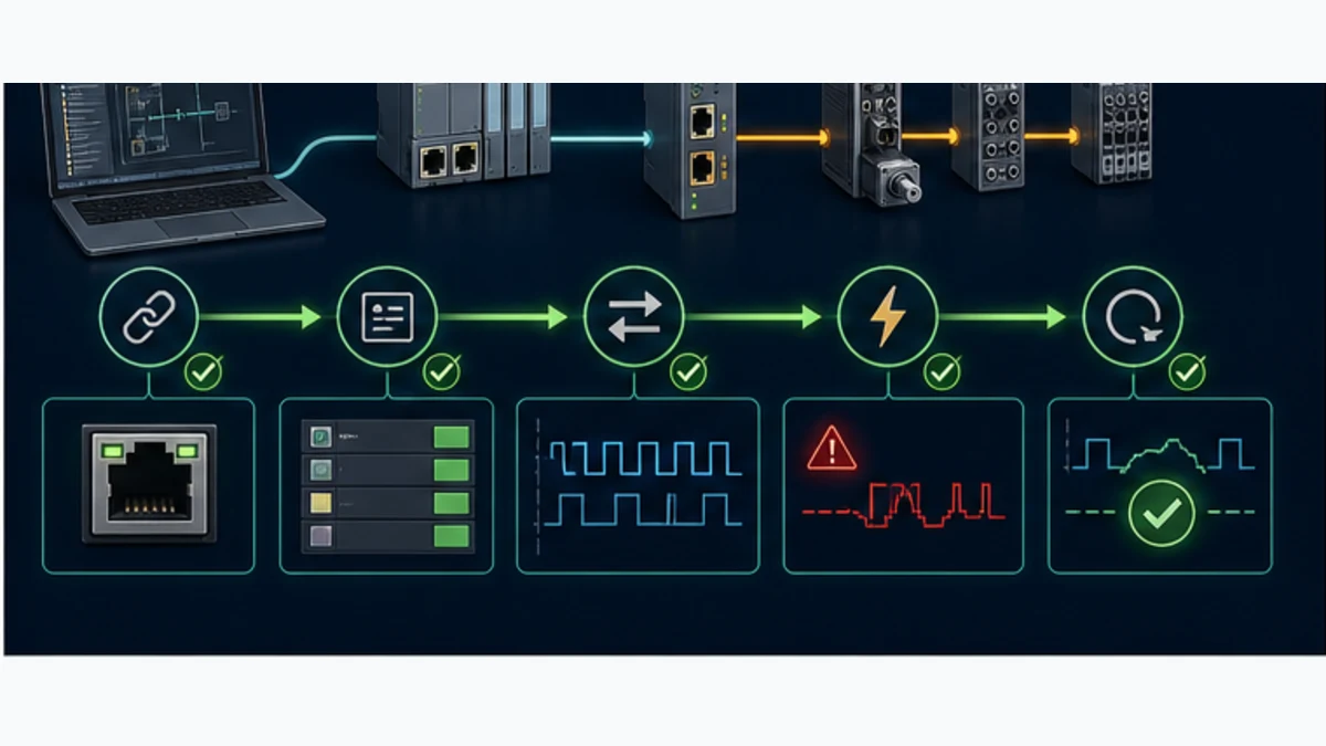
| Test | Stimulus | Expected S7 evidence | Expected EtherCAT/gateway evidence |
|---|---|---|---|
| PROFINET loss | disconnect approved S7-facing test link | device unavailable, data invalid, commands inhibited, first-fault timestamp retained | EtherCAT behavior follows documented gateway policy; no claim that it must stop unless configured |
| EtherCAT first-link loss | disconnect field-facing link in approved state | gateway remains reachable but EtherCAT/data-valid diagnostic fails | SubDevice count/state/WKC or gateway diagnostic identifies network-side failure |
| downstream device loss | remove power or link at a known position | application rejects affected data and avoids automatic restart | last visible device/port counters localize the boundary |
| stale remote logic | freeze heartbeat while both networks stay linked | freshness timer expires and consumer uses defined fallback | transport may remain healthy, proving why application heartbeat is required |
| map mismatch | load a controlled incompatible test version | contract version blocks commands | interface version/diagnostic identifies configuration mismatch |
| recovery | restore exact baseline and acknowledge | health rebuilds in sequence; restart remains deliberate | both networks return to approved states without hidden remapping |
Diagnose the first failed layer
Read both networks independently
The S7-1200 can see a healthy PROFINET Device while the gateway reports an EtherCAT failure. Conversely, the EtherCAT line can be operational while the PROFINET device name is wrong and the S7 cannot exchange data. Always capture four views: S7 device/module diagnostics, gateway system/protocol logs, EtherCAT MainDevice topology/state diagnostics and application-level freshness/contract status.
On EtherCAT, the Working Counter is incremented when addressed SubDevices process a datagram as expected. A mismatch proves unexpected participation; it is a powerful digital symptom but not a unique cause. Combine expected versus actual WKC with device order, AL state/status, link state and per-port error/lost-link counters. On PROFINET, check device identity/name, IP conflicts, module/slot consistency and controller diagnostics before rewriting application logic.
| Symptom | First discriminating evidence | Likely layer | Next controlled check |
|---|---|---|---|
| gateway absent in TIA Portal | online-access identity, device name and physical link | PROFINET identity/physical | assign verified device name; check duplicate IP/name and port |
| gateway online, all data bad | S7 module status plus gateway PROFINET connection | GSDML/slot image or firmware personality | compare exact configured input/output sizes and direction |
| PROFINET healthy, EtherCAT not OP | gateway EtherCAT state, AL code and visible device count | EtherCAT configuration/physical | compare ESI identity, order, power, first missing node and startup parameter |
| OP but WKC intermittent | expected/actual WKC and per-port error counters | EtherCAT physical/timing/device | localize by topology; inspect cable, EMC, power and failing port evidence |
| stable bytes but wrong numbers | raw hex at both sides and contract revision | representation/mapping | test known signed, endian and scale values one field at a time |
| correct values freeze | heartbeat/sequence age while link diagnostics remain good | remote application or gateway copy | prove which producer stopped changing and preserve first timestamp |
| drive reaches SAFEOP only | AL status, PDO assignment and watchdog/DC diagnostics | EtherCAT application configuration | match exact ESI/revision, PDO sizes, sync manager and DC mode |
| machine restarts after recovery | command latch, startup inhibit and acknowledgement record | application recovery design | require fresh command and proved readiness; do not mask with longer timeout |
Separate identity, state, data and meaning
A reliable fault tree asks four questions in order. Did the expected device answer with the correct identity? Did both protocol connections reach their required operational state? Are the expected bytes changing in both directions? Do those bytes carry valid, fresh engineering meaning? Each “yes” removes a layer. Skipping directly to ladder edits makes intermittent network faults harder to prove and can introduce a second defect.
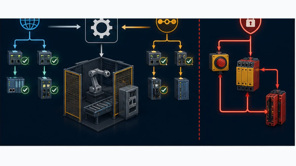
| Layer | Healthy proof | Misleading shortcut |
|---|---|---|
| physical | correct ports, power, link, shielding and error counters under load | link LED alone proves a valid protocol network |
| identity | exact PROFINET name/device and EtherCAT vendor/product/revision/order | a similarly named catalog object is close enough |
| protocol state | PN device/module healthy; required EtherCAT states and expected WKC | gateway web page opens, therefore both fieldbuses are operational |
| transport data | known test patterns arrive at the documented offsets/directions | values are nonzero, therefore mapping is correct |
| application contract | version, heartbeat, quality, range and sequence all pass | last received process value remains trustworthy forever |
| machine behavior | controlled normal, fault, loss and recovery tests pass | one successful start proves the integration |
| safety | approved safety requirements, architecture, validation and proof tests pass | ordinary gateway data or watchdog creates functional safety |
Bound safety, security and availability claims
Ordinary PROFINET-to-EtherCAT process data, gateway watchdogs and application heartbeats are not functional-safety channels. They can support standard-control diagnostics and command inhibition but do not create a required PL or SIL. PROFIsafe and FSoE are different safety communication mechanisms with approved devices, parameters, reactions and validation. A general protocol gateway should never be assumed to translate them. Keep emergency stop, guarding, STO and other risk-reduction functions in the approved safety architecture.
Define behavior for each communication loss: which ordinary commands de-energize, which controlled state is requested, which local controller remains responsible, what data becomes invalid, what alarm is raised, and what acknowledgement is needed. “Hold last value” may be reasonable for a displayed temperature and dangerous for a motion command. The risk assessment and functional specification decide; the gateway default does not.
Industrial gateways also create management interfaces, configuration files and firmware obligations. Place management access in the approved zone, change default credentials, restrict services, back up signed/checksummed configuration, record firmware and monitor vendor advisories. Do not route office traffic through an EtherCAT port or expose a configuration web interface merely because remote support is convenient. A replacement procedure must restore both network identities, the exact personality, the data contract and security settings.
| Control | Project evidence | Rejection condition |
|---|---|---|
| safe state | hazard-specific behavior for loss, stale data and restart | generic “outputs go safe” with no device-by-device definition |
| independence | safety function does not rely on ordinary mapped bits | run-permit bit is credited as the safety channel |
| access | named owners, least privilege and approved management path | shared defaults or gateway exposed beyond required zones |
| firmware/configuration | version, checksum, backup, restoration and rollback test | replacement depends on an engineer's laptop memory |
| monitoring | protocol state, freshness, first fault and maintenance diagnostics | only a common alarm without source or timestamp |
| lifecycle | supplier support, spare unit, compatible files and periodic proof | obsolete gateway becomes an undocumented single point of failure |
Procurement and design review checklist
Do not issue a gateway purchase order with only “S7-1200 to EtherCAT.” Attach a one-page role and acceptance specification. It should name the exact S7 CPU/firmware and TIA version, required PROFINET role, required EtherCAT role, SubDevice list, ESI revisions, PDO bytes, cycle and age requirement, mailbox/profile features, DC need, temperature/power/environment, diagnostics, configuration tool/license, cybersecurity expectations, certifications, safe response, spare strategy and the representative-hardware acceptance test.
Ask the supplier to confirm the exact order number and loadable firmware combination. If motion is involved, require a written statement of supported profiles/modes and measured application limits. If the project is only machine-to-machine exchange, specify that two controllers already exist and that the product must be a device/subdevice on the respective networks. These details prevent a technically real but role-inverted gateway from arriving on site.
| Review gate | Go evidence | Hold evidence |
|---|---|---|
| architecture | diagram names controller/device or MainDevice/SubDevice on every port | arrows only say “Ethernet” or “data” |
| product fit | supplier confirms exact simultaneous role pair and firmware | product page lists both protocols but no role combination |
| capacity | mapped bytes, device count and feature usage remain within documented limits with margin | estimate excludes diagnostics, expansion or mailbox needs |
| performance | measured worst-case age/jitter meets the application requirement | nominal cycle values are added on a spreadsheet only |
| diagnostics | faults can be localized to S7, gateway, EtherCAT position or application | one common healthy bit hides the failed side |
| recovery | power cycle, cable loss, device replacement and version mismatch are tested | communication restoration automatically restarts equipment |
| safety/security | approved specialists accept boundaries and controls | ordinary gateway is credited with unvalidated safety/security properties |
Frequently asked questions
Does the Siemens S7-1200 support EtherCAT natively?
Current Siemens S7-1200 and S7-1200 G2 technical documentation lists PROFINET IO controller/device capabilities for the integrated Ethernet interface, not a native EtherCAT MainDevice role. Treat EtherCAT as an external integration requiring a role-correct gateway, a separate EtherCAT controller or a different controller platform unless Siemens documents the exact target otherwise.
Can I connect an EtherCAT drive directly to an S7-1200 Ethernet port?
Not as a working EtherCAT network merely by connecting the cable. The S7 port and drive option must share a supported protocol and complementary roles. If the drive offers a compatible PROFINET option, that is usually the direct S7 path. Otherwise use an approved architecture with the required EtherCAT MainDevice.
What gateway role does an S7-1200 need to control EtherCAT I/O?
The S7-1200 is normally the PROFINET IO Controller, so the gateway must be a PROFINET IO Device toward the S7 and an EtherCAT MainDevice toward the SubDevice line. Verify that exact simultaneous role pair, firmware, device count, process-image size, PDO/profile functions and timing.
Is a PN/EtherCAT coupler the same as an EtherCAT MainDevice gateway?
No. A controller-to-controller coupler is commonly a device on both networks and transfers a bounded I/O image between an existing PROFINET controller and an existing EtherCAT MainDevice. It does not necessarily control a line of EtherCAT SubDevices. Read the role table, not only the product title.
Can TIA Portal configure EtherCAT devices behind the gateway?
TIA Portal configures the gateway's PROFINET-facing device from its GSDML and maps the S7 process image. An active gateway normally uses its own supported tool and the downstream manufacturers' ESI files for EtherCAT topology, PDOs, startup and timing. A coupler is configured separately in each controller's engineering tool.
What are GSDML and ESI files used for in this integration?
GSDML describes the gateway or coupler as a PROFINET Device to TIA Portal, including identity, modules, process data and diagnostics. ESI describes an EtherCAT SubDevice to the EtherCAT configuration tool. Neither file by itself defines the application meaning, freshness or safe response of the transferred bytes; the project data contract does that.
How do I detect stale data when both networks still look connected?
Transfer a changing application heartbeat or sequence number, calculate its age in the receiving controller, carry an explicit data-valid state and reject the interface when the maximum age or version contract fails. A static process value and green link LEDs cannot prove that the remote application is still executing.
Can a PROFINET-to-EtherCAT gateway be used for synchronized servo motion?
Do not assume so. A general process-image gateway introduces multiple update cycles and does not automatically merge PROFINET IRT and EtherCAT Distributed Clock domains. Use vendor-approved motion architecture and representative timing tests; keep tightly synchronized loops under a controller with documented native support.
What should I check first when the gateway is online but EtherCAT data is bad?
Keep the healthy PROFINET result, then inspect the gateway's EtherCAT MainDevice view: exact visible device count/order, identity/revision, state and AL status, expected versus actual Working Counter, PDO size/direction and per-port errors. If raw bytes move, compare known test patterns, endian, sign, scale, contract version and heartbeat age.
Does a gateway watchdog or heartbeat make the connection safety rated?
No. Ordinary mapped data, watchdogs and diagnostic heartbeats can improve standard-control fault handling but do not establish PL or SIL. Functional safety requires an approved safety requirements specification, architecture, components, communication mechanisms where used, calculations, validation and proof testing.
Practical next step
Write the required role pair at the top of the design: either S7 PROFINET Controller → gateway PROFINET Device / EtherCAT MainDevice → EtherCAT SubDevices, or S7 PROFINET Controller → machine coupler → existing EtherCAT MainDevice. Then freeze a 16- or 32-byte versioned contract and ask the selected supplier to confirm the exact order number, firmware and measured limits. That single step eliminates most incompatible gateway purchases before TIA Portal work begins.
Sources, review scope and limitations
This guide was reviewed on August 30, 2026. Product capabilities change by CPU, firmware, gateway personality, device revision, software version and region. The cited specifications establish current documented roles and concepts; only the approved project files and representative hardware prove a particular installation.
- Siemens, S7-1200 G2 system manual, V4.1 (December 2025).
- Siemens, S7-1200 G2 system manual, V1.0 (January 2025).
- Siemens, S7-1200 programmable controller system manual.
- Siemens Industry Mall, S7-1200 G2 CPU 1212C technical data.
- Siemens, SIMATIC S7-1200 G2 product resources.
- Siemens, S7-1200 diagnostic instructions for PROFINET and PROFIBUS.
- Hilscher, netTAP NT 151-RE-RE product page and supported roles.
- Hilscher, netTAP NT 151-RE-RE user manual.
- Helmholz, PN/EtherCAT Coupler product page and technical data.
- Helmholz, PN/EtherCAT Coupler quick-start guide.
- EtherCAT Technology Group, EtherCAT technology: functional principle, MainDevice and ESI.
- EtherCAT Technology Group, ESI specification downloads and current schema information.
- EtherCAT Technology Group, EtherCAT diagnostics for users.
- EtherCAT Technology Group, ETG.2200 EtherCAT implementation guide.
- EtherCAT Technology Group, device-user and OEM conformance guidance.
- PROFIBUS & PROFINET International, GSDML specification for PROFINET.
- PROFIBUS & PROFINET International, standard GSD libraries and GSDML purpose.
- PROFIBUS & PROFINET International, PROFINET Design Guideline, January 2025.
Now run it · free to start
Follow plant data from sensor to SCADA
Fieldbus versus Ethernet, Modbus, EtherNet/IP, PROFINET, OPC UA and MQTT, then SCADA layers and alarms, taught on simulated equipment. Free to start.
Ownership disclosure: PLC Programming IO and PLC Simulation Software are operated by the same publisher.
PLC Programming IO Editorial Team
Industrial automation education, references, and software testing
The PLC Programming IO Editorial Team publishes sourced industrial-automation education and documents how material is reviewed, tested, and corrected. A team byline means the publisher is responsible for the page; it does not represent a fictional person or imply an engineering licence.
Coverage:
- • PLC programming concepts and examples
- • Vendor software tutorials and comparisons
- • SCADA, HMI, protocols, and instrumentation
- • Training, careers, and reference material
Review standard:
- • Prefer primary and official sources
- • Record software versions when material
- • Separate tested facts from estimates
- • Publish material corrections
Important scope note
This site provides education, not project-specific engineering approval. Safety, code, and compliance decisions require a qualified person with access to the actual machine and jurisdiction.