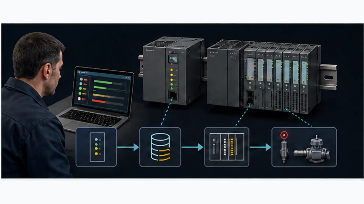
Siemens PLC Programming: TIA Portal Tutorial
Build, simulate, download and diagnose a Siemens S7-1200 or S7-1500 project in TIA Portal with an evidence-led motor-control example.
Direct answer
To program a current Siemens S7-1200 or S7-1500, first identify the exact CPU article number, hardware revision and firmware. Create that target in SIMATIC STEP 7 inside TIA Portal, configure its modules and network, define symbolic tags and data types, place reusable equipment logic in a function block with an instance data block, and call it from the intended organization block. Compile hardware and software, test normal and negative cases in a supported Siemens simulation or isolated bench, compare the approved offline project with the correct online target, then download through a controlled commissioning procedure. Finish only when I/O, sequence, diagnostics, restart and recovery evidence pass—not when the project merely compiles.
As reviewed on 29 August 2026, Siemens identifies TIA Portal V21 as the current major framework release. That does not mean every installed CPU, firmware, library or project should be upgraded to V21. The supported combination depends on exact hardware, engineering edition, update level, hardware-support packages, option packages and licences. Preserve the approved toolchain and use current Siemens compatibility information for the target.
This tutorial owns the general Siemens PLC programming task: hardware configuration, tags, block structure, motor logic, simulation, controlled download and diagnosis. Start with the platform-neutral PLC programming pillar when the question is the field-I/O model, scan/task behavior or language comparison rather than Siemens engineering. The Siemens S7 family guide owns controller selection; the S7-1200 programming guide owns a model-specific setup; and the STEP 7 legacy guide owns S7-300/S7-400 Classic engineering and migration. LOGO! Soft Comfort, formal training and certification remain separate intents.
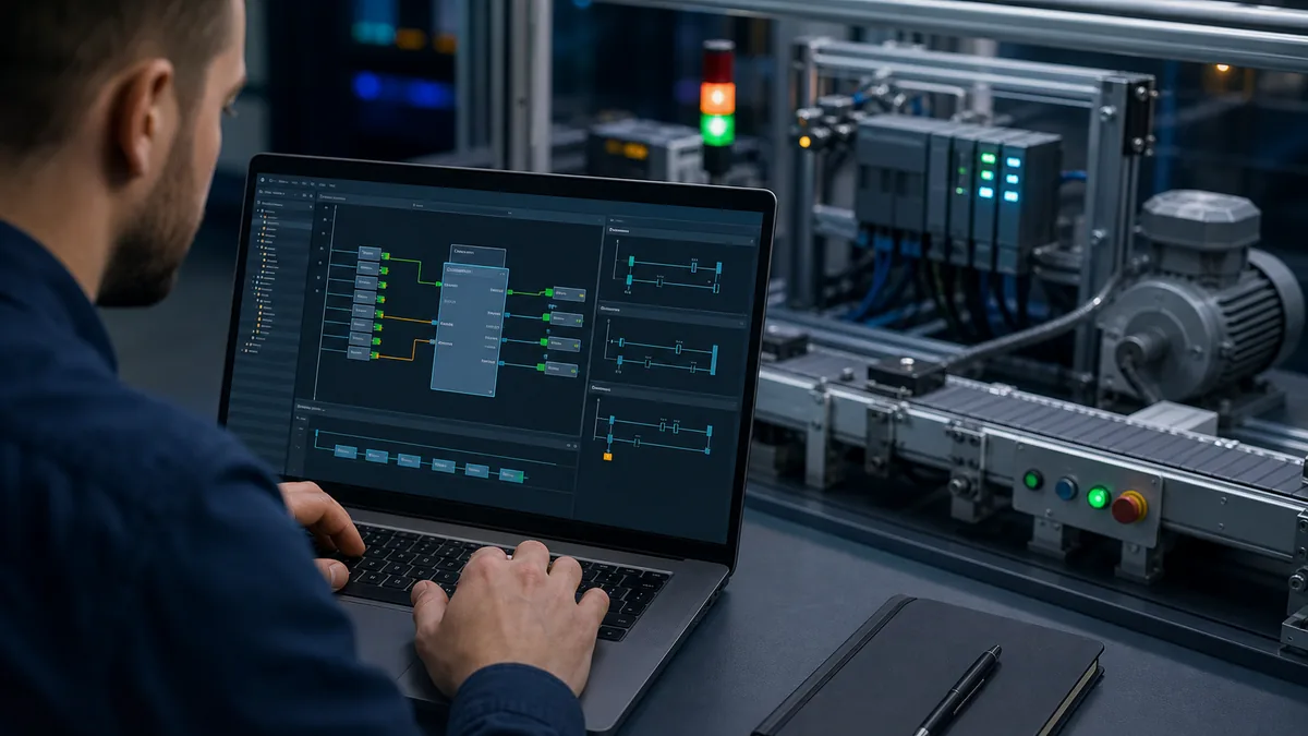
Siemens PLC programming workflow at a glance
| Stage | Engineering action | Proof before moving on | Common failure |
|---|---|---|---|
| identify | record CPU, hardware, firmware, modules and engineering environment | target manifest matches the cabinet or approved lab | selecting “an S7-1200” by family name |
| specify | write modes, states, permissives, feedback, alarms and restart behavior | reviewed state and I/O contracts | coding from an informal sequence description |
| configure | create exact device, modules, addressing and network | hardware compile and slot/address review pass | allowing the catalogue to choose the design |
| structure | create types, tags, FB/FC/DB interfaces and OB calls | cross-reference shows one deliberate owner per command | writing the entire machine in OB1 |
| implement | build one equipment module and sequence around explicit states | code review links every transition to a requirement | latching outputs without feedback or timeout |
| verify | compile, simulate, trace and run negative/recovery cases | expected versus observed evidence is saved | testing only the happy path |
| commission | verify target, compare, back up, download and prove physical I/O | approved identity, change and rollback controls pass | downloading to the first reachable device |
| hand off | archive source, versions, test results, deviations and restore path | another authorized engineer can reproduce the baseline | treating the laptop as the backup |
Before opening TIA Portal
Freeze the target and software manifest
“Siemens PLC” is not a programmable target. At minimum, record CPU article number, hardware revision, installed firmware, power/I/O module articles, network interfaces, project TIA Portal release and update, STEP 7 edition, hardware-support packages, libraries, option packages, licences and the approved project checksum. Capture the physical label and read-only online identity when authorized.
S7-1200 G2 is a separate hardware generation. Siemens states that it is not hardware-compatible with the previous S7-1200 family, although project conversion can be possible with checks. Do not import an older bill of materials, I/O layout or accessory assumption into a G2 project. S7-1500 is also a family with several performance, fail-safe and technology variants; specify the exact CPU rather than claiming a feature for every S7-1500.
| Manifest field | Example form—not a recommendation | Source of truth | Acceptance rule |
|---|---|---|---|
| controller identity | article, hardware revision, serial | physical label and authorized online view | exact expected device |
| firmware | installed and configured versions | online diagnostics and approved project | supported combination documented |
| modules | article per rack/slot | cabinet, drawings and project tree | every slot reconciled |
| engineering | TIA release, update and STEP 7 edition | controlled workstation | reproducible build |
| additions | HSPs, libraries, Safety/motion/test options | installation and licence records | required functions compile |
| source | archive, version, checksum and approval | configuration repository | known baseline restores |
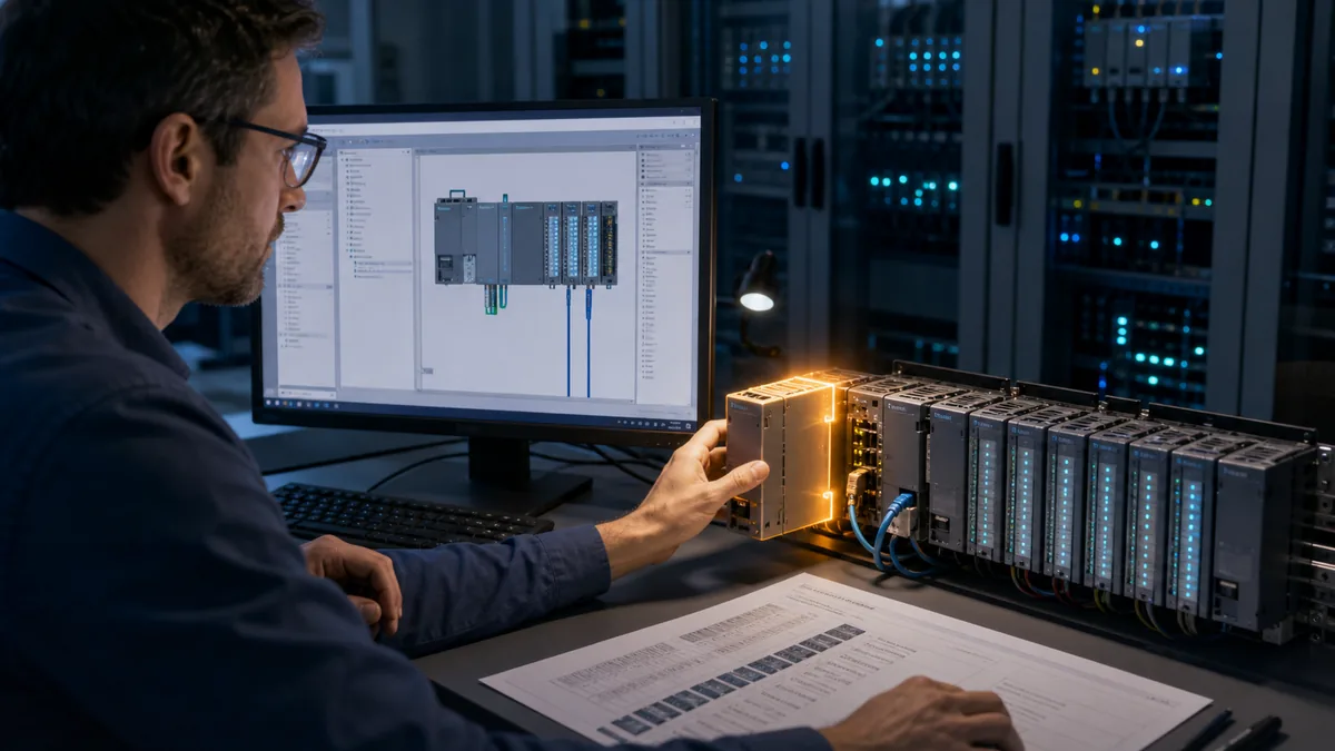
Write the behavior contract first
Use a small but complete first project: a motor-driven conveyor with local and remote requests, start and stop, an external run-permissive, running feedback, a start timeout, an overload input, a reset rule and restart inhibition. The example is general control logic; it is not a safety function and the motor output is not energy isolation.
Describe behavior without editor syntax. A valid start request while permissives are true moves the equipment from Ready to Starting. Command turns on. Feedback received before the timer expires moves it to Running. Missing feedback, overload, lost permissive or a contradictory signal moves it to a defined fault or stopping state. Reset is accepted only when the cause is clear and the request is removed. After power restoration, the equipment does not start merely because a retained or external request is true unless the approved process requirement explicitly demands and validates that behavior.
| Input or state | Meaning | Invalid or fault case | Required response |
|---|---|---|---|
| start request | operator or sequence asks to run | both start and stop active | stop priority and diagnostic |
| run permissive | non-safety process conditions allow start | drops during run | defined stop and cause record |
| overload | protective device status presented to PLC | active or implausible | command off; reset inhibited |
| running feedback | controlled equipment actually responded | absent after command | timeout and fault |
| mode | local, remote or maintenance ownership | two owners conflict | one deterministic owner |
| reset | acknowledge after cause cleared | held continuously | edge/rule prevents auto-reset loop |
| startup state | behavior after CPU restart | stale request remains | no unintended start |
Create the TIA Portal project
Add the exact CPU and modules
Create a new project under the controlled engineering environment. Add the device using the exact order information and firmware that the project must target. Add signal, communication and technology modules in their physical slots. If the device is absent from the catalogue, stop and resolve the TIA version or hardware-support-package boundary from Siemens information; do not choose a similar module to silence the editor.
Configure addresses deliberately. Symbolic programming reduces dependence on absolute addresses, but the I/O mapping still has a physical contract. Maintain an I/O schedule that ties terminal, channel, electrical type, engineering tag, direction, normal state, range/unit and diagnostic behavior together. Compile the device configuration and resolve warnings by meaning, not by bulk acceptance.
Configure the network without guessing
Assign an approved device name, IP settings and subnet. Confirm whether the programming interface is an isolated bench, commissioning network or production network and follow site authorization. For every external device, document protocol role, identity, data layout, type, units, update behavior, timeout, stale-data response and recovery. “PROFINET connected” does not specify a usable interface.
| Network item | Define | Positive proof | Negative proof |
|---|---|---|---|
| engineering access | interface, route, role and approved window | correct target is discovered | wrong target is rejected |
| remote I/O | device identity, slots, update and diagnostics | each channel maps correctly | missing/mismatched station is diagnosed |
| HMI | tag owner, command arbitration and quality | request/status are distinct | stale/bad quality is visible |
| drive | control/status words, scaling and timeout | command and feedback agree | network loss causes defined response |
| supervisory link | role, variables, quality, time and rights | representative data load passes | loss does not corrupt core control |
Structure a maintainable Siemens program
Use OBs, FBs, FCs and DBs deliberately
Organization blocks are execution entry points for cyclic, startup, timed, hardware or diagnostic events supported by the target. An FB is appropriate for reusable equipment with persistent instance state. An FC is useful for a calculation or transformation that does not require its own instance memory. A DB stores structured global or instance data. User-defined data types make repeated interfaces consistent.
For the motor example, create a MotorControl FB and one instance DB per motor. Call the instance once from the intended cyclic execution path. Keep hardware mapping at a boundary: physical input becomes an engineering signal; application logic works with named and typed values; physical output is driven from an approved command. This separation makes forces, simulation and field diagnosis easier to reason about.
| Program object | Owns | Good example | Warning sign |
|---|---|---|---|
| cyclic OB | scheduling and high-level calls | call equipment and sequence layers | thousands of unrelated instructions |
| startup OB | deliberate initialization | set nonretained startup requests safe | hiding normal control inside startup |
| FB | stateful reusable behavior | motor command, timer, state and diagnostics | direct global I/O scattered through it |
| FC | stateless transformation | scaling or validated conversion | relying on hidden mutable storage |
| instance DB | one FB instance state | one motor's state and timers | shared by unrelated equipment |
| global DB | reviewed shared structures | commands, status and configuration contract | unstructured dumping ground |
| UDT | repeatable typed interface | motor request/status/diagnostic records | anonymous bit arrays without ownership |
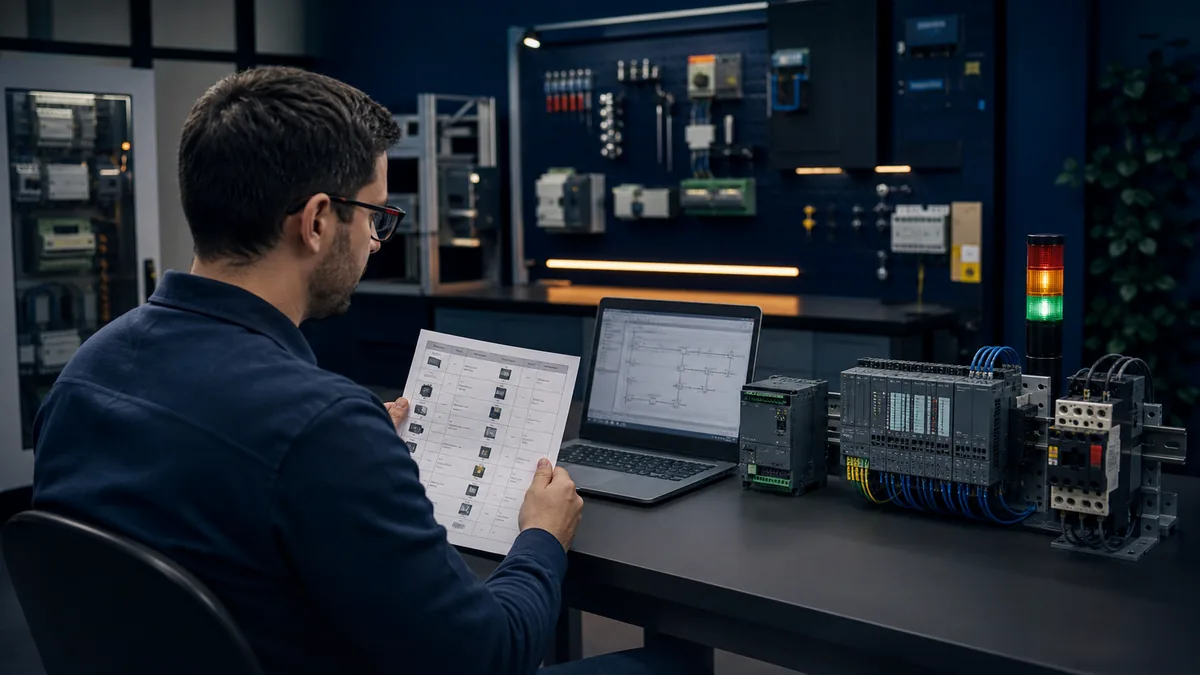
Prefer symbolic, typed interfaces
Use names that expose role: StartRequest, RunPermissive, RunCommand, RunningFeedback, StartTimeoutActive and FaultCause. Direction matters. A request is not a physical command, and a command is not proof of motion. Avoid tag names that embed a temporary address or panel location unless that identity is the real engineering meaning.
Siemens' S7-1200/S7-1500 programming guideline recommends structured, reusable components and documents optimized data-access concepts. Treat a change between optimized and standard access as an interface and compatibility decision, especially where HMIs, communications, legacy code or absolute addressing are involved. Do not claim one setting is universally correct without examining every consumer.
Choose LAD, FBD or SCL by task
STEP 7 provides graphical and textual programming options. LAD often communicates discrete interlock and relay-style behavior clearly to technicians. FBD can make signal flow and function connections readable. SCL is effective for typed calculations, loops, arrays, state transitions and data manipulation. GRAPH may suit qualified sequential tasks where the installed licences, target and team standard support it.
Language choice does not replace architecture. A short SCL block can still hide state; a visible ladder network can still have conflicting coils. Use one state owner, explicit interfaces, comments that explain requirement or failure behavior, and reviewable naming in every language.
Program the motor example
Separate arbitration from equipment behavior
Resolve local, remote, automatic and maintenance requests before the motor FB. The FB should receive one validated run request and relevant permissives rather than decide which screen, sequence or pushbutton wins. That creates a testable contract: request arbitration can be tested separately from equipment response.
Within the FB, calculate permissive status, state transitions, command, feedback timeout and diagnostic cause. Give stop and protective conditions clear priority. Never use this standard example as safety logic. Emergency stopping, guard monitoring and safe torque-off require a risk assessment, qualified safety architecture, validated safety program and the exact fail-safe product documentation.
| State | Entry condition | Command | Exit or fault condition |
|---|---|---|---|
| Disabled | not enabled or mode forbids control | off | enable plus valid ownership |
| Ready | enabled, stopped and permissive | off | valid request → Starting |
| Starting | request and permissives true | on | feedback → Running; timeout → Fault |
| Running | feedback agrees with command | on | stop/lost permissive → Stopping; overload → Fault |
| Stopping | command removed | off | feedback clears → Ready; timeout → Fault |
| Fault | a latched reviewed cause exists | off | cause clear plus valid reset → Ready |
Make faults diagnostic, not merely latched
Retain a structured cause or code that distinguishes no feedback, overload, permissive loss, contradictory feedback, network quality and startup inhibition. Preserve first-out information where the requirement calls for it. A single Fault Boolean may be convenient for an HMI lamp, but it is not enough for diagnosis or acceptance.
Timers need units and intent. Name a start-feedback timeout after the event being measured and configure it from reviewed process evidence. Do not copy a two-second value from an article into a large fan, hydraulic pack or valve. For every timer, record trigger, reset, behavior across modes, behavior across restart and the physical evidence used to choose its setting.
Keep HMI commands from owning outputs
The HMI should send requests or setpoints through an explicit interface. The PLC remains responsible for arbitration, permissives, state and outputs. Use command handshakes, access roles and quality indication as needed. If the HMI disconnects, the equipment must follow the reviewed PLC behavior rather than inherit an accidental last screen value.
Compile and review before simulation
Compile hardware and software. Read every diagnostic and warning in context. Confirm the configured target, block calls, interface changes, data conversions, retentive selections and resource use. Use cross-references to locate every writer of critical commands, states, modes and reset signals. A command with multiple uncontrolled writers is an architectural defect even when compile succeeds.
Perform a static review against the behavior contract. Check one owner per output, deterministic stop priority, no unintended start after restart, explicit bad-quality behavior, bounded timers, retained data justification, reset conditions, alarm cause, and absence of forces in the approved baseline. Record the review, toolchain and checksum.
| Review surface | Question | Reject when |
|---|---|---|
| target | does project identity match intended CPU/modules/firmware? | family-only or substitute target |
| calls | is each stateful instance called exactly as designed? | missing, duplicate or conditional surprise |
| writers | who writes command, mode, state and configuration? | ownership is ambiguous |
| retention | what survives restart and why? | every value is retained by convenience |
| conversion | are types, limits, units and overflow behavior explicit? | implicit conversion changes meaning |
| safety | is standard control separated from safety functions? | standard bit treated as safety proof |
| access | are observation, download, force and mode rights governed? | shared unrestricted engineering access |
Simulate the Siemens PLC program
Label the test environment
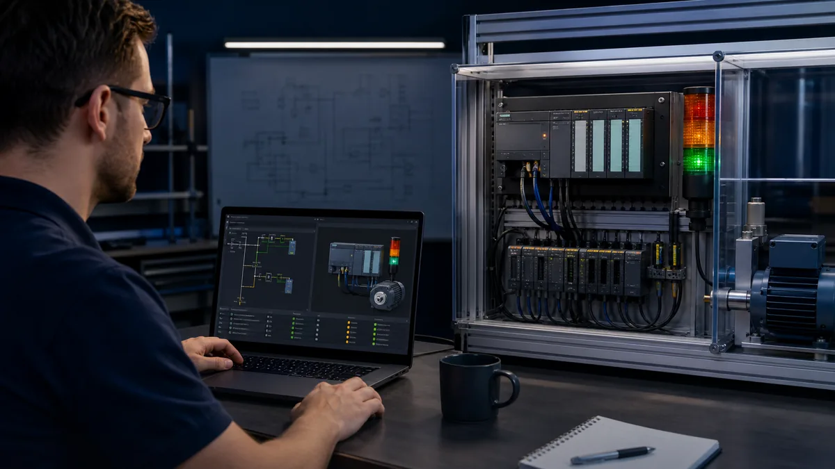
A requirements walkthrough, compile, supported PLCSIM execution, PLCSIM Advanced environment, isolated physical controller and final field acceptance establish different evidence. Record CPU model/firmware representation, TIA/PLCSIM version, simulated I/O and communications, exclusions and test result. Never label a simulated motor bit as physical commissioning.
Siemens lists PLCSIM Advanced and Test Suite as TIA Portal options, and current educational support pages list versioned trial/download resources. Exact support and licensing change by version and target. Verify the current product documentation rather than downloading an unofficial package.
Run normal, negative and recovery cases
Start from a known state and drive interfaces rather than editing arbitrary internal memory. For every test, record precondition, stimulus, expected state/command/diagnostic, observed result and evidence location. At minimum run idle, valid start, normal stop, denied start, permissive loss while running, no-feedback timeout, overload, reset denied, reset accepted, communication-quality loss, CPU restart and restoration from the approved project.
| Test case | Stimulus | Expected result | Still unproved in simulation |
|---|---|---|---|
| valid start | request with all permissives | Starting, command on, feedback leads to Running | motor and wiring response |
| denied start | request with one permissive false | command stays off; reason visible | physical contact integrity |
| no feedback | command on; feedback absent | timeout, command off, first cause retained | actual mechanical jam behavior |
| overload | overload signal active | fault response and reset rule | protective-device trip performance |
| communication loss | external quality bad/stale | defined degraded behavior | final network recovery timing |
| restart | interrupt and restore simulated CPU | no unintended start; justified retention | cabinet power sequence |
| restore | load approved archived project | known baseline and test set reproduce | field asset and process match |
Watch tables and traces are evidence tools, not acceptance by themselves. Monitor the request-to-command-to-feedback chain and state transitions. Avoid indefinite forcing. If an authorized force is necessary in an isolated test, list every force, its owner and removal verification. A force left active can invalidate later results and create field risk.
Download and commission safely
Verify before any write
Production commissioning requires site authorization, hazard controls and a rollback plan. Confirm machine/process state, safe work boundary, target identity, approved source/checksum, online/offline comparison, backup, protected access, communication path and affected stakeholders. If the discovered target does not exactly match expectation, stop. Do not alter its name, IP address or firmware merely to make the download dialog proceed.
Choose the minimum approved load scope only after reviewing what TIA Portal reports will change and whether data can be reinitialized, the CPU can change mode, or connected equipment can move. Version-specific online-change features have conditions and consequences; consult the exact target help/manual and site procedure. Never infer that “download without stop” means “change without process risk.”
Prove physical I/O before automatic operation
With the process isolated under the approved procedure, verify each input and output from terminal/drawing through project tag and device. Confirm normally open/closed interpretation, analog range/unit, channel diagnostics, actuator direction, feedback and loss behavior. An online green status cannot prove a mislabeled terminal or reversed actuator.
Bring the system through manual or bounded test states before automatic sequence. Execute the approved normal, negative, restart and recovery matrix. Record actual timing and differences from simulation. Restore forces, bypasses and temporary settings to the approved state and have an independent check where required.
Diagnose Siemens PLC programming faults
Find the first failed boundary
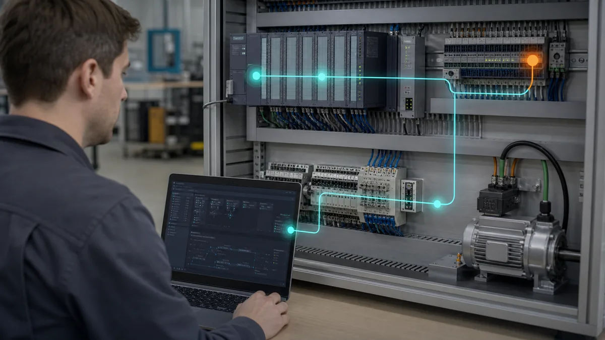
When a project does not compile, cannot find the CPU, will not download or runs without moving the equipment, avoid random edits. Diagnose in order: engineering environment, target identity/version, project configuration, access/protection, CPU state/diagnostics, application state, mapped I/O, communication quality, field feedback and process. The first divergence from expected evidence determines the next test.
Siemens' current S7-1200 G2 manual exposes online and diagnostic tools such as identity, cycle/memory monitoring and the diagnostics buffer. S7-1500 documentation provides system-diagnostics and trace context. Tool availability and paths vary, so anchor the workflow to the exact version help and device manual.
| Symptom | First evidence | Likely boundary | Controlled next action |
|---|---|---|---|
| CPU absent from catalogue | exact article/firmware and installed HSPs | engineering support | verify approved TIA/HSP path |
| online target not found | interface, route, subnet and physical link | access/network | read-only discovery on approved interface |
| download target mismatch | configured versus discovered identity | target/project | stop and reconcile exact identity |
| block will not compile | first diagnostic and interface change | program/type/option | correct one root error, then rebuild |
| CPU in STOP | mode transition and diagnostics buffer | configuration/runtime/hardware | preserve evidence before clearing cause |
| command is false | request, owner, state and permissives | application | trace the first false condition |
| command true, output false | mapping, channel state and diagnostics | I/O configuration | compare tag to configured channel |
| output true, no equipment response | terminal, protection and feedback | field/process | follow electrical/mechanical procedure |
| intermittent sequence | timestamped state/quality/feedback trace | timing/communications/process | reproduce one controlled disturbance |
Diagnose a motor that will not start
Begin with the state, not the coil. Is the module Disabled, Ready, Starting or Fault? Is there one valid request owner? Which permissive is false? Was reset denied? If command is false, stay inside the application evidence. If command is true but mapped output is false, inspect I/O mapping and channel diagnostics. If the physical output energizes but the motor does not run, the problem crosses into electrical protection, starter/drive, wiring, energy and mechanical boundaries that require qualified procedures.
After any correction, return to the known baseline, rerun the failed test, then regress valid start/stop, permissive loss, feedback timeout, overload, communication loss and restart. Record “expected versus observed” rather than “works now.”
Acceptance and evidence handoff
Use an acceptance matrix
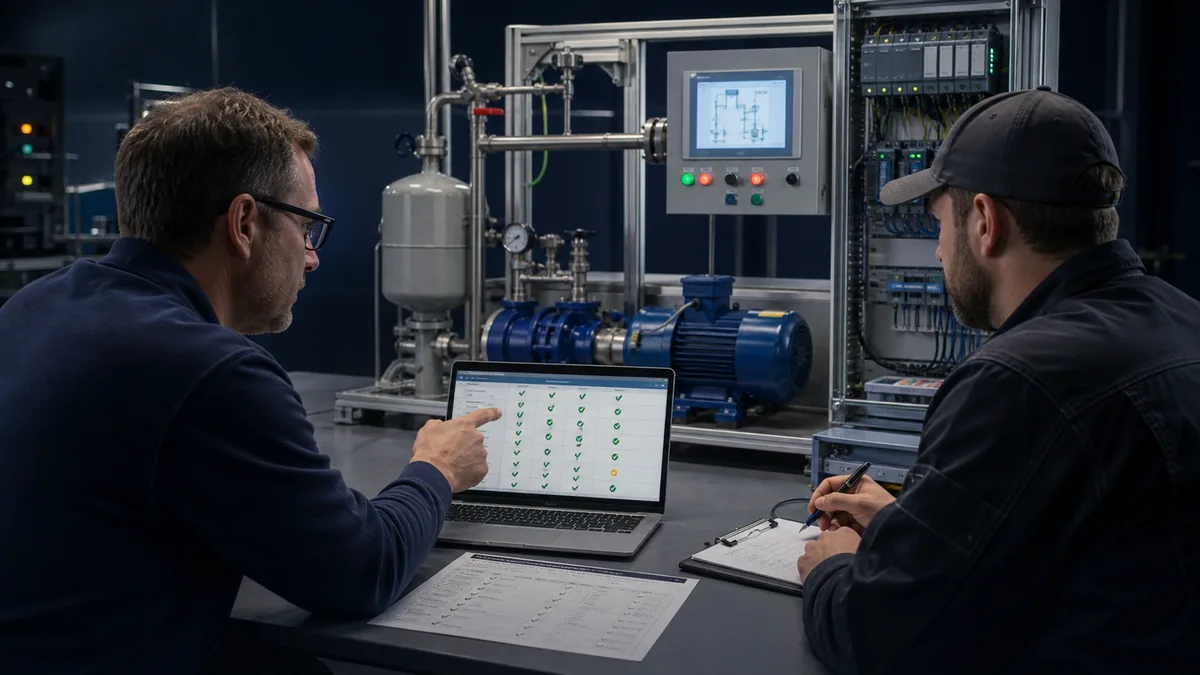
A production-ready first project has traceable proof. Requirements map to program objects and test cases. Tests identify environment and exact version. Deviations name owner and disposition. Backup/restore and rollback are demonstrated at the appropriate layer. Safety and cybersecurity reviews remain separate, qualified workstreams rather than checkboxes inside a standard motor block.
| Acceptance gate | Positive evidence | Negative/recovery evidence | Retained artifact |
|---|---|---|---|
| identity/build | exact target compiles | wrong target is rejected | manifest and build log |
| equipment module | valid request reaches Running | permissive/feedback/overload faults are deterministic | trace and cause table |
| I/O | every approved channel responds correctly | open/bad-quality/channel fault is visible | signed I/O record |
| communications | representative data exchange passes | loss, stale state and reconnect behave as specified | interface test report |
| restart | approved state recovers | no unintended start | restart trace |
| source control | approved source loads and matches | unapproved/mismatched source is blocked | archive and checksum |
| recovery | backup restores on approved target | failure path and rollback are executable | recovery record |
Hand off a reproducible project
Archive the project source, checksum, TIA/STEP 7 versions and updates, HSPs, libraries, option/licence dependencies, CPU/module/firmware manifest, network and I/O contracts, requirements, test results, trace files, diagnostics, deviations, change approval, backup, rollback and restore instructions. Remove temporary forces and record verification. Store credentials and sensitive network information through the organization's approved secure mechanism, not in article examples or uncontrolled project comments.
Safety and cybersecurity boundaries
Standard PLC logic is not a substitute for a risk assessment, safety function or lockout/tagout. Use qualified personnel and exact safety-product manuals for fail-safe hardware/software, signatures, proof testing and change control. Never force, mask or bypass protective functions to complete this tutorial. OSHA's hazardous-energy guidance and the employer's procedure govern work on affected equipment in the United States; apply the relevant jurisdiction and site requirements elsewhere.
Engineering access is an OT security boundary. Inventory devices and firmware, segment networks, use named least-privilege accounts, approve remote access, protect project source/backups, manage certificates and time, log changes, review advisories and test recovery. Siemens' industrial-cybersecurity guidance states that secure operation depends on a holistic concept; NIST SP 800-82 and CISA ICS advisories provide broader OT controls and vulnerability context. Product protection does not replace operational governance.
Siemens PLC programming answer map
| Question | Concise answer | Detailed surface |
|---|---|---|
| How do I program a Siemens PLC? | Configure the exact target in STEP 7/TIA, structure blocks/tags, compile, test and commission under control. | workflow and project sections |
| Which software programs Siemens S7? | Current S7-1200/S7-1500 engineering uses STEP 7 in TIA Portal; exact editions and versions vary. | manifest and sources |
| What is OB1? | The standard cyclic organization-block entry point; it should schedule deliberate calls, not become the whole architecture. | block structure |
| Should I use FB or FC? | Use an FB when reusable behavior needs instance state; use an FC for a stateless transformation. | object matrix |
| How should tags be named? | Name engineering role and direction, not a temporary address. | typed interfaces |
| Can I test without hardware? | Supported simulation can test selected logic; it cannot prove physical I/O, safety or process response. | simulation boundaries |
| How do I download safely? | Verify authorization, state, target, comparison, backup, impact and rollback first. | commissioning gate |
| Why will the motor not start? | Find the first divergence across request, state, permissive, command, output and feedback. | diagnostic table |
| What should the handoff contain? | Source/checksum, toolchain, target manifest, contracts, tests, deviations, backup and recovery. | evidence handoff |
| Where do I learn S7-1200 specifics? | Continue to the distinct S7-1200 first-project owner. | canonical boundary links |
Installed-base and timer diagnostics
Use the S7-200 identity, support and migration guide when an installed controller could be a traditional S7-200, S7-200 SMART or mistaken S7-1200. Use the Siemens PLC watchdog-timer guide when the problem is cycle supervision, OB/task behavior, timeout ownership or a first-out diagnostic path rather than general programming.
Frequently asked questions
What software is used for Siemens PLC programming?
SIMATIC STEP 7 inside TIA Portal is Siemens' engineering software for configuring and programming current SIMATIC controllers. STEP 7 Basic is a subset of Professional; supported controllers, options and licences depend on the exact release and target. Legacy S7-300/S7-400 projects may use STEP 7 Classic or supported TIA paths. Verify the approved project rather than installing the newest version by default.
Is TIA Portal the same as STEP 7?
No. TIA Portal is the integrated engineering framework. STEP 7 is the PLC configuration and programming software within that framework. A TIA project may also include HMI, drives, safety and other components, each with version and licence dependencies.
How do I create my first Siemens PLC project?
Record exact CPU/module/firmware identity, create that device in TIA Portal, map I/O, define symbolic tags, build a stateful equipment FB with an instance DB, call it from the cyclic OB, compile, simulate normal/fault/restart cases and only then use an approved controlled download and physical I/O test.
What is the difference between an OB, FB, FC and DB?
An OB is an execution entry point. An FB is a reusable block with persistent instance state. An FC is generally a reusable stateless transformation. A DB stores structured global or FB-instance data. Exact behavior and supported OB types depend on the CPU and firmware.
Should Siemens PLC beginners use ladder logic or SCL?
Use the language that makes the task and team review clearest. LAD often suits discrete interlocks; SCL suits typed calculations, arrays and explicit state logic; FBD suits connected functional flow. Architecture, naming, ownership and tests matter more than the language. A first project can use LAD for motor conditions and SCL for a bounded calculation while sharing the same typed interface.
Can I simulate a Siemens PLC without hardware?
Yes, for targets and functions supported by the matching Siemens simulation environment. Record the exact TIA/PLCSIM version and exclusions. Simulation does not prove wiring, I/O electrical behavior, protection, physical timing, safety or final process response. Repeat relevant cases on an isolated target and during controlled field acceptance.
Why can TIA Portal not find or download to my PLC?
Check the selected engineering interface, physical link, subnet/routing, approved device access, exact CPU identity, configured target, firmware support, protection and CPU state in that order. Stop on an unexpected device. Do not change its name, address or firmware just to make it reachable.
How do I troubleshoot Siemens PLC logic online?
Preserve the CPU state and diagnostic evidence, then trace one chain: request owner, equipment state, permissives, command, mapped channel and physical feedback. Use cross-references, watch/trace and the diagnostics buffer where supported. Change one cause, rerun the failed case, then run regression and restart tests.
Can I use a browser PLC simulator instead of Siemens PLCSIM?
A vendor-neutral browser simulator can teach scan behavior, ladder patterns, timers, state, permissives and fault recovery. It is not Siemens PLCSIM, does not execute proprietary SIMATIC firmware and cannot validate TIA Portal compatibility, Siemens hardware, safety or commissioning. Use it for general practice and repeat target-specific evidence in the supported Siemens environment.
What files should I hand over after Siemens PLC commissioning?
Hand over controlled source and checksum, TIA/STEP 7 build details, HSPs/libraries/options, CPU/module/firmware manifest, I/O and network contracts, requirements, review/test evidence, diagnostics, deviations, backup, rollback, restore procedure and verification that forces or temporary bypasses are removed. Store credentials separately through the approved secure system.
Practise the general control pattern
Use PLC Simulation Software to practise request/command/feedback separation, motor states, timers, permissive loss, missing feedback and reset behavior before opening a production project. Ownership disclosure: PLC Programming operates PLC Simulation Software. It is a browser-based vendor-neutral learning simulator, not Siemens PLCSIM, a SIMATIC firmware emulator, TIA Portal or a substitute for Siemens hardware and field commissioning. Current scope and limitations are in the versioned product facts.
Continue with the S7-1200 first-project guide, TIA Portal tutorial, PLC programming examples or Siemens error-code workflow for the narrower next task.
Official sources, review scope and limitations
This independent editorial tutorial was reviewed on 29 August 2026. Software, firmware, manuals, catalogues and licences change. Verify the exact target and current official documentation at the point of work.
- Siemens SIMATIC STEP 7 in TIA Portal
- Siemens TIA Portal V21 release
- Siemens S7-1200 G2 product overview
- Siemens S7-1200 G2 system manual
- Siemens S7-1500 product overview
- Siemens S7-1500 and ET 200MP system manual
- Siemens programming guideline for S7-1200/S7-1500
- Siemens safety programming guideline for S7-1200/S7-1500
- Siemens S7-1500 diagnostics function manual
- Siemens S7-1500 communication function manual
- Siemens diagnostics overview for S7-1200/S7-1500
- Siemens TIA Portal options
- Siemens TIA Portal Test Suite application-test example
- Siemens TIA Selection Tool
- Siemens SIMATIC Automation Tool
- Siemens SCE technical support and current educational downloads
- Siemens industrial cybersecurity
- NIST SP 800-82 Rev. 3
- CISA industrial-control-system advisories
- OSHA control of hazardous energy
Illustrations are generated editorial scenes, not Siemens product photographs, editor screenshots, wiring drawings or proof of a tested product. Example names, states and timings are teaching structures, not production values. Exact manuals, the risk assessment, employer procedures, cybersecurity program and qualified commissioning evidence take precedence.