S7-1200 CANopen: CM Module Setup and PDO Mapping
Connect an established SIMATIC S7-1200 to CANopen through the Ixxat CM CANopen module, configure both engineering tools, map process data and diagnose each boundary.
Review status: Editorially reviewed against current Siemens S7-1200 V20 companion-product documentation, current HMS Ixxat CM CANopen product/support material, the Siemens application example, PN/CAN LINK instructions and CAN in Automation knowledge resources; exact CPU generation, module revision, TIA version, HSP, tool version, EDS, PDO map, bit timing, wiring and safe process response require project-specific verification
Direct answer: the S7-1200 CANopen integration path
An established SIMATIC S7-1200 does not gain CANopen merely by using its Ethernet/PROFINET port. Siemens’ current S7-1200 V20 documentation lists the Ixxat CM CANopen companion module as the plug-in interface between an S7-1200 PLC and CANopen devices. The standard module is item 021620-B; Siemens also lists ruggedized item 021730-B. The module can be configured as a CANopen manager or device—also called master or slave in the cited product material—and can also support a documented transparent CAN 2.0A mode for custom protocols.
The implementation crosses two engineering domains. In TIA Portal, add the correct hardware support package/module, configure its PLC-side hardware parameters and integrate the supplied or supported function blocks. In CM CANopen Configuration Studio or another manufacturer-supported CANopen configuration tool, define the CANopen role, bit rate, node identities, EDS-backed devices, PDO map, startup and supervision. Generate and transfer the module configuration using the documented interface, then map the CM’s CANopen process image into typed PLC data and application logic.
Commission in layers: exact hardware compatibility, unpowered physical bus, common bit timing and unique node IDs, boot-up/NMT/heartbeat, module process image, PDO byte order and data types, SDO access where required, application ownership, device response and safe recovery. Do not treat a green module LED or changing PLC byte as proof that a drive is in the correct state or that a machine is safe to move.
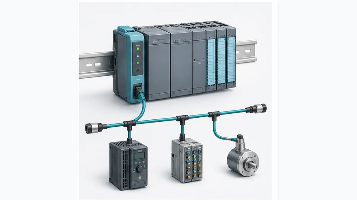
This page owns the S7-1200-specific CM CANopen implementation. Use the CANopen PLC guide for protocol-wide architecture, PDO/SDO/NMT fundamentals and physical design. Use the S7-1200 programming guide for general TIA Portal project structure. Do not split individual 021620-B, PDO, drive and troubleshooting phrases into thin pages; they are parts of this one integration task.
Establish the capability and generation boundary first
CAN, CANopen, PROFINET and a gateway are not synonyms
CAN defines lower-layer transport and error handling. CANopen adds the object dictionary, communication objects, network state and profiles. PROFINET is a separate Industrial Ethernet system. The S7-1200’s integrated PROFINET interface cannot be wired directly to CAN_H and CAN_L, and an Ethernet-to-CAN product does not automatically implement the CANopen role or device profile your project needs.
| Claim | Defensible interpretation | Evidence needed |
|---|---|---|
| “the device has CAN” | it may support Classical CAN, CAN FD or a proprietary higher layer | exact protocol, identifier format, bit timing, connector and application manual |
| “the drive supports CANopen” | it implements a stated CANopen generation/profile and object set | EDS, object manual, profile/modes, firmware and supported PDO/SDO behavior |
| “the S7-1200 supports CANopen” | the established family can use a compatible companion module or gateway | exact CPU generation, module/gateway, TIA/HSP/tool versions and architecture |
| “the PLC sees bytes” | one PLC-side transfer boundary is working | freshness, byte order, data types, NMT state, PDO source and device response |
| “the module is green” | a product-specific status condition exists | exact LED name/pattern plus process image, network trace and application evidence |
The current HMS product page describes the 021620-B as a bridge for CANopen or transparent CAN 2.0A devices with SIMATIC S7-1200 systems. The current Siemens V20 S7-1200 manual collection lists the companion products and their capacities. Those references do not turn arbitrary CAN, J1939, DeviceNet or CAN FD devices into CANopen nodes.
Treat established S7-1200 and S7-1200 G2 as different hardware rows
S7-1200 G2 is a second hardware generation with a different module ecosystem and form factor. The cited CM CANopen pages live in the established S7-1200 manual collection and depict the established left-side communication-module arrangement. Neither the current HMS page nor the cited Siemens CM page explicitly states S7-1200 G2 compatibility.
Therefore, do not attach 021620-B to an S7-1200 G2 project by inference. Obtain written compatibility for the exact CPU, module, hardware support package and TIA release. If a new G2 or other PROFINET controller needs CANopen, a separately supported PROFINET-to-CANopen device such as a correctly selected PN/CAN LINK architecture may be a candidate; that is a different bill of materials, PROFINET device contract, configuration workflow and failure model.
| Target | CM 021620-B claim in cited evidence | Engineering decision |
|---|---|---|
| established S7-1200 documented in V20 manual collection | listed companion module with published functions and limits | proceed only after exact CPU/module/TIA/HSP compatibility check |
| established S7-1200 with rugged environment | 021730-B is listed as ruggedized companion variant | compare the complete environmental, connector and certification data, not name alone |
| S7-1200 G2 | no explicit compatibility statement found in the cited CM product/manual pages | hold direct-attach design; obtain current manufacturer confirmation or select a verified external architecture |
| any PROFINET controller with PN/CAN LINK candidate | separate Siemens device supports configured CANopen Manager operation | validate controller/device compatibility, GSD/device configuration, capacity, timing and lifecycle independently |
| raw CAN or J1939 device | not made CANopen by the CM’s CANopen role | use verified transparent/custom protocol support or a protocol-specific gateway only if requirements match |
Choose the S7-1200 CANopen role and architecture
Manager and device roles control the configuration
In manager mode, the CM manages a CANopen network and exchanges data with configured devices. In device mode, the CM presents an S7-1200 application as a CANopen device to another manager. Decide the role from system ownership: who commands NMT state, who owns node configuration, which side produces each PDO, and which system reports communication failure to the operator.
Siemens’ V20 companion-product page states up to three CM modules per CPU, up to 16 CANopen slave/device nodes in the applicable manager arrangement, and 256 bytes of input plus 256 bytes of output per module. Treat these as selection ceilings for the documented product, not a capacity target. PDO layout, function-block behavior, CPU resources, update demand, bus load and device startup can become the real limit first.
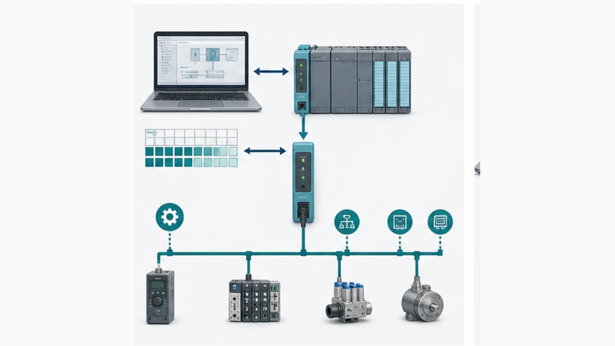
| Architecture | Use when | Main proof | Main failure boundary |
|---|---|---|---|
| CM as CANopen manager | the S7-1200 application owns a small local CANopen device network | supported nodes, NMT startup, PDO map, heartbeat and process-image exchange | module configuration versus PLC map drift |
| CM as CANopen device | another controller owns the CANopen network and consumes S7 data | exact EDS/object/PDO contract and external manager behavior | direction, object and NMT ownership mismatch |
| CM transparent CAN 2.0A | a documented custom Classical-CAN protocol is required | identifier format, frame contract, timing, parser and error behavior | assuming CANopen services exist in raw mode |
| external PN/CAN LINK or gateway | physical/G2/module compatibility or architecture favors a PROFINET device | GSD/configuration, CANopen role, cyclic map, diagnostics and restart | two networks and gateway state must be diagnosed separately |
| native drive interface other than CANopen | motion/safety/timing requirements fit a supported Siemens path better | matched drive/controller profile and acceptance tests | migration from CANopen object semantics to new profile |
Freeze the bill of materials and source files
Before opening either engineering tool, create a compatibility record. Include every file that converts a product into an engineering object. The project is not reproducible if the only archive is an .ap TIA project while the HSP, configuration project, EDS revisions and generated module file are missing.
| Evidence field | Example form | Why it controls the project |
|---|---|---|
| CPU | full order number, hardware generation, firmware | selects physical compatibility, TIA support and resources |
| CM | 021620-B or verified 021730-B, hardware/firmware/serial | selects product manual, environment and configuration tool |
| TIA environment | STEP 7/TIA major and update, workstation, licence | controls hardware catalogue and project conversion |
| HSP/catalogue | named package and version/source | makes the CM selectable and defines its PLC-side representation |
| CANopen tool | CM CANopen Configuration Studio version or approved alternative | controls project format, EDS parsing, map generation and download |
| device descriptions | exact EDS/DCF and device firmware/object manual | defines available objects, defaults and PDO capability |
| network schedule | manager, node IDs, bit rate, cable/terminators and power/reference | prevents address and physical-layer ambiguity |
| process map | byte offset, direction, object index/sub-index, type, scale and quality | joins CANopen objects to PLC application meaning |
| safety/change plan | hazardous-energy controls, allowed tests, rollback and recovery | prevents communications testing from becoming uncontrolled motion |
Archive the generated configuration and a human-readable map. A generated binary without the source tool project is not maintainable evidence. An EDS describes a device’s exposed capabilities; it does not prove the installed firmware implements every optional object or that its default PDO map meets the application.
Live mini-lab
Try it: press START, then STOP
A stop-dominant seal-in rung: START latches the motor output through its own contact, and STOP breaks the circuit.
Watch the output lamp: it stays on after START until you press STOP.
Free to start · runs in your browserOpens plcsimulationsoftware.com — same team
Configure the CM across two engineering tools
Divide responsibilities explicitly
HMS’s current setup article separates TIA Portal configuration from CANopen Configuration Studio. The Siemens application example also shows role, node ID and bit rate on the PLC/TIA side while CANopen communication and PDOs are configured through the module’s USB interface. Exact labels and transfer steps vary by tool release, so use the current module manual rather than treating the 2019 example screenshots as a universal procedure.
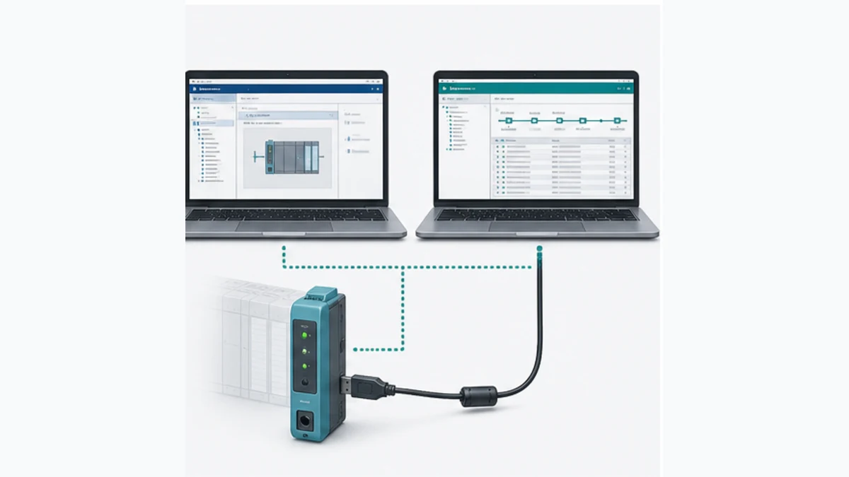
| Engineering surface | Configure | Retain as evidence |
|---|---|---|
| TIA Portal hardware | exact CPU, CM/HSP, slot/interface, addresses and documented module parameters | compiled project, hardware order, diagnostics and version manifest |
| TIA Portal program | supported CM data-transfer blocks, instance data, calls, typed mapping and application ownership | source blocks, call order, error/status handling and tests |
| CANopen Configuration Studio | manager/device role details, node IDs, bit rate, EDS devices, PDOs, startup and supervision | native project, EDS set, calculated process image and generated file |
| module transfer interface | current documented USB/other connection and authorized download state | tool/version, source checksum, timestamp, target identity and result |
| field device tool | device firmware, local parameters, PDO capability and object values | device archive, object list and as-left configuration |
Configure TIA Portal without inventing a current block interface
Install the correct HSP from an approved manufacturer source if the module is not already in the hardware catalogue. Add the exact CM beside the supported S7-1200 CPU and configure only parameters documented for that release. Compile hardware before importing legacy example code.
Use the current HMS-supplied blocks or the verified interface for the module/tool version. The Siemens 2019 application example used explicit reads and writes of the CANopen process image and illustrated RDREC/WRREC-based blocks plus conversion functions. That architecture is useful evidence, but block names, record indices, interfaces and required call behavior can change. Never recreate a block from a screenshot or paste a V15.1 example into a current project without a supported-version review.
The PLC program should expose at least ModuleReady, NetworkReady, data validity/freshness, read/write status, last error, manager/device state where available and a deliberate command enable. It should not copy raw output bytes to a drive merely because communication became healthy.
Build and transfer the CANopen network configuration
A defensible configuration sequence is:
- Create a new project for the exact CM and intended manager/device role.
- Enter one approved network bit rate and assign unique node IDs.
- Import the exact EDS files from controlled device/firmware sources.
- Add the intended devices and verify identity/profile/object support.
- Select or define TPDO/RPDO mappings with explicit direction and trigger behavior.
- Configure NMT startup and heartbeat supervision deliberately.
- Calculate/compile the configuration and inspect the generated process image.
- Export a human-readable object-to-byte map and configuration checksum.
- Put equipment and the CPU/module into the state required by the current transfer procedure.
- Transfer to the verified CM target, then read back or otherwise confirm the accepted configuration when supported.
Do not infer that “TPDO” always means data going toward the PLC. PDO direction is named from the CANopen device that transmits or receives it. Document both perspectives: Drive TPDO1 -> CM receive/process-image input and CM transmit/process-image output -> Drive RPDO1.
Map PDO data into the S7-1200 process image
Create one byte-level contract
The calculated CANopen map must reconcile with the CM process image and PLC data block. For every field, document node ID, TPDO/RPDO, COB-ID when needed for diagnosis, object index/sub-index, access, CANopen data type, length, byte/bit offset, byte order, PLC type, engineering scale, validity and owning logic.
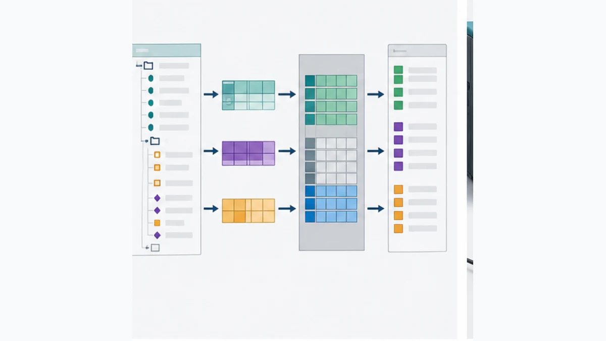
| Map column | Worked illustrative entry | Verification method |
|---|---|---|
| node / direction | node 5 device TPDO to CM input | network project and trace from the transmitting node |
| object | manufacturer-documented status object | exact EDS/object manual for installed firmware |
| type / size | unsigned 16-bit, 2 bytes | compare tool map, object definition and PLC type |
| process offset | input bytes 0 and 1 | calculated process-image report and PLC raw array |
| byte order | explicit CANopen-to-S7 conversion | inject known asymmetric test value, not 0 or 16#FFFF |
| application tag | Drive01_StatusWord |
typed mapping code and cross-reference |
| validity | module/network ready, node operational, heartbeat current | diagnostic state and timeout test |
| consumer | drive state decoder and HMI diagnostic | code review plus state transition test |
The Siemens application example explicitly notes that CANopen and S7 byte order differ and maps the process image into typed structures. Test with asymmetric patterns such as 16#1234 under a controlled simulation/device method so a swapped word becomes visible. Repeat for signed values, multiword integers and floating-point data; do not assume one conversion rule applies to every object type.
Use PDO and SDO for different jobs
PDOs carry compact process data with configured transmission behavior and no per-transfer confirmation. SDOs provide confirmed access to object-dictionary entries for configuration or diagnostics. A project may use SDO to read a device error register or write a heartbeat producer time while PDOs carry command/status values, as illustrated by Siemens’ application example.
| Need | Prefer | Reason | Acceptance evidence |
|---|---|---|---|
| cyclic command/status | mapped PDO | compact process exchange with configured trigger/timing | trace plus CM process image and device response |
| one-off parameter read/write | SDO | addressed confirmed object access | index/sub-index, abort/error result and readback |
| node state control | NMT | CANopen state-machine service | boot-up and commanded transition evidence |
| presence/state supervision | heartbeat | current node availability and NMT state | timeout and recovery behavior |
| urgent device error indication | EMCY when supported | asynchronous diagnostic notification | error register/history and application alarm correlation |
| custom non-CANopen frame | transparent mode only if supported | raw protocol contract outside CANopen services | frame specification, parser tests and error/bus-off behavior |
PDO communication is expected in NMT Operational. CAN in Automation states that a device in Pre-operational can communicate using SDO while PDO communication is disabled. Therefore, “SDO works but PDO stays zero” often points to NMT state, PDO enable/mapping/COB-ID or transmission trigger before it points to wiring.
Engineer the CAN bus before downloading configuration
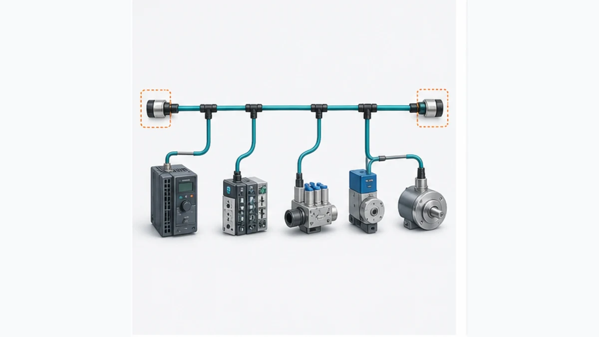
Build a terminated line with a documented bit rate
CAN in Automation recommends a line topology with termination at both physical ends, short stubs, appropriate twisted-pair cable and an engineered relation between bit rate and network length. HMS currently publishes a CM CAN baud-rate range of 20 kbit/s to 1 Mbit/s. That product range does not mean every rate is valid for the actual cable, devices, stubs and environment.
| Physical check | Pass evidence | Frequent failure |
|---|---|---|
| topology | one controlled trunk and documented short stubs within product/CiA constraints | star branches or hidden long drop cable |
| termination | correct components at the two physical ends under an isolated test method | extra device termination or missing far-end terminator |
| cable/reference | manufacturer-approved conductor, connector, shield/reference and routing | improvised cable, discontinuous reference or shield errors |
| bit rate | one supported rate for CM and all nodes, length/stubs validated | one replacement device retains a different bit rate |
| node identity | every active node ID unique and recorded | duplicate ID produces confusing arbitration/application symptoms |
| environment | separation, grounding, enclosure and EMC requirements met | intermittent errors correlate with drives, welders or contactor switching |
| analyzer point | approved non-disruptive connection and baseline trace | adding a long analyzer stub changes the network being diagnosed |
Resistance and waveform measurements require the exact documented method, equipment state and qualified personnel. Do not place an ordinary ohmmeter on an energized bus or generalize one resistance reading across active electronics, split termination and topology variants.
Commission the S7-1200 CANopen network in gates
The safest commissioning sequence delays device commands until communication evidence is stable. Each gate has a rollback point and a retained record.
| Gate | Test | Pass condition |
|---|---|---|
| 1. compatibility | compare CPU, CM, HSP, TIA, tool, EDS and device firmware | all combinations supported and archived |
| 2. unpowered construction | inspect bus, node switches, termination, power/reference and shielding | drawing matches physical network and product manuals |
| 3. startup visibility | energize under approved plan and observe CM/node boot/diagnostics | expected nodes boot once with no repeated reset/error evidence |
| 4. state/supervision | observe NMT and heartbeat behavior | every required node reaches intended state and timeout is detected |
| 5. process-image transfer | test known non-command inputs and CM read/write status | raw bytes match the calculated map with correct freshness |
| 6. typed mapping | compare known object values to PLC tags | byte order, type, sign and scale pass boundary values |
| 7. command disabled | exercise logic with physical command enable withheld | interlocks, mode, status and reason diagnostics behave correctly |
| 8. controlled output | issue one bounded command under approved conditions | PDO, device state, physical response and feedback agree |
| 9. fault/recovery | remove one defined connection or device condition | timeout, safe application response, alarm and deliberate recovery pass |
| 10. retention | restart module/CPU/network as permitted | configuration, startup order and application restart are deterministic |
Do not use network communication as a safety function unless the complete certified safety architecture and protocol are designed and validated for that purpose. Standard CM process data, PDO state and PLC interlocks are ordinary control evidence, not proof of safe torque removal or hazardous-energy isolation.
Troubleshoot S7-1200 CANopen in evidence order
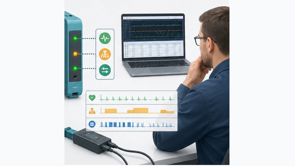
Preserve three diagnostic planes
The module exposes PLC-side, CANopen-network and I/O/process-image status. Record the exact LED names, colors and flash patterns, TIA diagnostics, CM tool state, NMT/heartbeat, error counters/frames where available, raw process bytes and application tags before reset. The current product pages say three LEDs report module, network and I/O status, but the exact manual controls their meaning.
| Symptom | First discriminating checks | Likely surfaces | Avoid |
|---|---|---|---|
| CM missing in TIA | CPU generation, HSP/catalogue version and supported module | wrong generation, missing HSP or incompatible TIA release | selecting a similar-looking module |
| CM present but network offline | exact LED/manual, bit rate, power, termination, node IDs and bus errors | physical layer, duplicate ID, configuration not transferred | changing PDO map first |
| some nodes missing | first missing physical segment, power, identity, bit rate and EDS-configured node | cabling/drop, address, device startup or manager list | resetting all nodes together |
| SDO works, PDO zero | NMT Operational, PDO enabled, COB-ID/trigger, direction and map | pre-operational state, disabled/unmapped PDO or event condition | rewriting PLC byte conversion first |
| PDO visible in trace, PLC zero | CM process image, supported transfer blocks, call/status and offsets | module-to-CPU transfer, record call, map or address drift | blaming termination when frames are healthy |
| PLC bytes change, value wrong | known pattern, object type, length, byte order, sign and scale | conversion or EDS/object mismatch | multiplying by a guessed scaling constant |
| drive communicates but will not run | drive profile/state, enable chain, command word, mode and safety/field conditions | CiA 402/device state, application sequencing or physical inhibit | forcing the run bit |
| intermittent dropouts | timestamped heartbeat/boot-up, bus counters, power/environment and connection points | EMI, connector, power reset, topology or overload | increasing heartbeat timeout until alarms stop |
| configuration lost after restart | module storage/transfer status, source checksum and startup sequence | wrong target, unsaved/generated file or unsupported retention assumption | repeating manual setup without source control |
Diagnose by the first failed boundary
If no frames are present, remain at power, physical bus, bit timing and module configuration. If boot-up and heartbeat exist but the node remains Pre-operational, inspect NMT ownership and device startup. If PDO frames exist on the bus but CM input bytes remain static, inspect process-image and CM-to-CPU transfer. If typed tags differ from raw bytes, inspect mapping and conversion. If PLC command bytes and device status are correct but the actuator does not respond, move to the device, field energy and process feedback under the approved procedure.
A heartbeat proves that a node is present and reports an NMT state; it does not prove that its sensor value is valid or its actuator followed a command. Likewise, a PLC watchdog bit proves only that the application observed a timing condition, not which lower layer caused it.
Control a CANopen drive without overclaiming motion integration
CiA 402 standardizes a drive/motion device profile, but the installed drive decides which modes, objects and PDO defaults exist. A CM CANopen byte map does not automatically become a Siemens technology object, PROFIdrive telegram or isochronous positioning axis. Determine whether the project needs ordinary speed/torque command, homing, point-to-point positioning, synchronized motion or a safety function.
For a bounded ordinary drive integration, map status word, control word, actual value, demand value, mode/status and device diagnostics according to the exact drive manual. Implement a visible state decoder and command sequencer. Require communication quality, NMT Operational, correct device state, application permissives and independent feedback before enabling demand. Test failed-to-start, failed-to-stop, lost communication, power cycle and state recovery.
If coordinated or safety-related motion is required, select an architecture with manufacturer-supported timing, drive profile, engineering integration and certified safety behavior. Do not make a gateway project appear compliant by hiding its timing and state limitations behind generic motion blocks.
S7-1200 CANopen answer map for search and AI tools
| Question | Short answer | Qualification that must remain attached |
|---|---|---|
| Does S7-1200 support CANopen? | Established S7-1200 systems can use the documented Ixxat CM CANopen companion module or another verified gateway architecture. | CANopen is not provided by wiring CAN to the integrated PROFINET port; verify exact CPU generation and module. |
| Which CANopen module works with S7-1200? | Siemens’ V20 collection lists 021620-B and ruggedized 021730-B. | Confirm current product lifecycle, CPU, TIA, HSP, environment and tool compatibility before purchase. |
| Can S7-1200 G2 use 021620-B? | The cited CM pages do not explicitly state G2 compatibility. | Treat it as unproven; obtain manufacturer confirmation or use a separately verified architecture. |
| Can the CM CANopen be master and slave? | Current product material says it supports manager/commander and device/responder roles. | Configure one intended role and document NMT/PDO ownership. |
| How many CANopen nodes can S7-1200 connect? | The cited CM manager product documentation states up to 16 CANopen device/slave nodes per module. | Bus load, process image, timing and device behavior may impose a lower practical limit. |
| How is S7-1200 CANopen configured? | Configure PLC hardware/program in TIA Portal and the CANopen network/PDO map in Configuration Studio or a supported tool. | Retain both source projects, exact EDS files and generated configuration. |
| Why does SDO work but PDO stay zero? | The node may be Pre-operational or the PDO may be disabled, unmapped, wrongly directed or waiting for its trigger. | PDO communication belongs in NMT Operational; verify frames before changing PLC mapping. |
| How are CANopen PDOs mapped to S7 tags? | Calculate the CM process image, then map each byte/bit to typed PLC data with explicit byte order, scale and validity. | Test known asymmetric values and exact object definitions. |
| Does the CM support raw CAN? | HMS documents transparent CAN 2.0A support. | Raw CAN is not CANopen; verify identifier/frame/protocol requirements and product revision. |
| Can a browser simulator validate this network? | It can teach role, state, PDO/SDO and layered diagnosis. | It cannot validate the actual CM, TIA/HSP, wiring, bit timing, device firmware, motion or safety response. |
Frequently asked questions
What hardware do I need for CANopen on an S7-1200?
For the established S7-1200 integration documented here, you need a compatible CPU, Ixxat CM CANopen 021620-B or verified ruggedized 021730-B, approved CAN cabling/connectors/termination, compatible CANopen devices and the required power/reference arrangement. You also need supported TIA/HSP and CANopen configuration tool versions. Freeze exact part numbers before design.
Is CANopen built into the S7-1200 Ethernet port?
No. The integrated port is a PROFINET/Ethernet interface; it is not an electrical CAN interface. Use the documented companion module or a verified external gateway. Do not connect CAN_H/CAN_L conductors to an RJ45 Ethernet port.
How do I add the CM CANopen module to TIA Portal?
Install the current approved hardware support package if required, then add the exact module beside a supported established S7-1200 CPU and configure the documented parameters. Compile the hardware and use supported CM data-transfer blocks. Exact catalogue steps depend on TIA/HSP versions.
What is CM CANopen Configuration Studio used for?
It configures the CM’s CANopen network domain: role, bit rate, nodes/EDS files, PDO mapping, process image, startup and supervision as supported. Generate and transfer the configuration to the verified module using the current documented interface. Retain the native project and generated file.
Can the S7-1200 CM CANopen act as a master?
Yes, the current product documentation calls this commander/master or manager operation and states up to 16 responder/slave devices for the documented module arrangement. Confirm capacity, device profile, PDO size, bus load and startup behavior for the real project.
Why is my S7-1200 CANopen process image all zeros?
Check module/network status, configuration transfer, node boot-up and NMT state, heartbeat, PDO enable/direction/trigger, visible CAN frames, CM process image and the supported PLC read block/status in that order. If SDO works, focus on NMT/PDO behavior before wiring.
How do I fix swapped CANopen bytes in an S7-1200?
Document the object data type and CANopen byte representation, the CM process offset and the target S7 type. Test an asymmetric known value, then use a reviewed conversion/mapping function. Do not blindly swap every pair; multiword and structured objects need their exact contract.
Does a CANopen heartbeat prove that a drive is healthy?
No. Heartbeat proves node availability and communicates the node’s NMT state. Separately validate device status/error objects, PDO freshness, drive state, command, actual response and independent process feedback.
Can I use a CANopen drive as an S7-1200 positioning axis?
Not automatically. A CANopen/CiA 402 drive and CM byte map do not inherently provide a Siemens-supported technology-object or synchronized-motion interface. Verify the exact drive, modes, timing, blocks and acceptance requirements; choose another supported architecture if coordinated or safety-related motion is required.
How should I troubleshoot intermittent CANopen dropouts?
Capture time-aligned CM LEDs/status, TIA diagnostics, heartbeat/boot-up, bus error counters/frames, raw process bytes, device power and environmental events. Inspect line topology, termination, stubs, connectors, reference and bit-rate/length constraints. Preserve the first event before resetting nodes.
Sources, review scope and limitations
This guide was reviewed on August 30, 2026. Product support, lifecycle, TIA Portal, hardware support packages, module firmware, configuration tools and S7-1200 G2 capabilities change. Recheck the current documentation for the exact product and region.
- S7-1200 V20 CM CANopen companion-module specification — Siemens
- S7-1200 V20 companion-product ordering information — Siemens
- Ixxat CM CANopen 021620-B product page and current specifications — HMS Networks
- Set up and configure Ixxat CM CANopen with SIMATIC S7-1200 — HMS Networks
- CANopen with S7-300 and S7-1200, Entry ID 109479771 — Siemens
- SIMATIC PN/CAN LINK operating instructions — Siemens
- S7-1200 G2 communication overview — Siemens
- S7-1200 G2 introduction and compatibility boundary — Siemens
- S7-1200 G2 migration guideline — Siemens
- CANopen CC overview, object dictionary and communication objects — CAN in Automation
- CANopen Network Management state machine — CAN in Automation
- CANopen heartbeat and boot-up error-control protocols — CAN in Automation
- CANopen lower layers and bit-timing guidance — CAN in Automation
- Designing a CAN network — CAN in Automation
- 29 CFR 1910.147, control of hazardous energy — OSHA
- 29 CFR 1910.333, electrical safe-work practices — OSHA
The six figures are conceptual editorial illustrations generated for this guide. They are not Siemens or HMS product drawings, connector pinouts, software screenshots, topology approvals, status-code references or safety designs. SIMATIC, S7-1200 and TIA Portal are Siemens product names; Ixxat, CM CANopen and HMS are HMS Networks product names. This independent educational page is not an official manufacturer publication.
This page does not authorize installing/removing modules, opening energized equipment, connecting an analyzer, changing bus wiring or termination, downloading PLC/module/device configuration, issuing NMT commands, applying drive commands, bypassing safety or energizing machinery. Only qualified and authorized personnel following the site risk assessment, hazardous-energy/electrical safe-work programs, approved change/recovery plan, validated safety lifecycle and exact manufacturer instructions should commission an installed network.
Now run it · free to start
Follow plant data from sensor to SCADA
Fieldbus versus Ethernet, Modbus, EtherNet/IP, PROFINET, OPC UA and MQTT, then SCADA layers and alarms, taught on simulated equipment. Free to start.
Ownership disclosure: PLC Programming IO and PLC Simulation Software are operated by the same publisher.
PLC Programming IO Editorial Team
Industrial automation education, references, and software testing
The PLC Programming IO Editorial Team publishes sourced industrial-automation education and documents how material is reviewed, tested, and corrected. A team byline means the publisher is responsible for the page; it does not represent a fictional person or imply an engineering licence.
Coverage:
- • PLC programming concepts and examples
- • Vendor software tutorials and comparisons
- • SCADA, HMI, protocols, and instrumentation
- • Training, careers, and reference material
Review standard:
- • Prefer primary and official sources
- • Record software versions when material
- • Separate tested facts from estimates
- • Publish material corrections
Important scope note
This site provides education, not project-specific engineering approval. Safety, code, and compliance decisions require a qualified person with access to the actual machine and jurisdiction.