S7-1200 IO-Link: SM 1278 Setup, Mapping and Diagnostics
Connect IO-Link devices to an established Siemens S7-1200 with the SM 1278 or a compatible PROFINET master, configure TIA Portal and S7-PCT, map process data and prove replacement behavior.
Review status: Editorially reviewed against current Siemens S7-1200, S7-1200 G2, SM 1278, SIMATIC IO-Link system, S7-PCT and LIOLink library documentation plus current IO-Link Community specifications; exact CPU generation, module, firmware, TIA Portal/HSP, master, IODD, device, port power, mapping, parameter, replacement, timing, cybersecurity and safety behavior require project-specific verification
Direct answer: add a compatible IO-Link master to the S7-1200
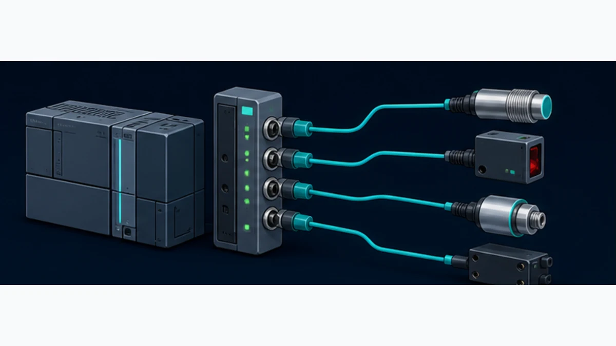
An S7-1200 communicates with an IO-Link sensor or actuator through an IO-Link master, not by treating the CPU's ordinary digital input as an IO-Link port. For the established S7-1200 hardware generation, Siemens lists the SM 1278 4xIO-Link Master, article number 6ES7278-4BD32-0XB0, as a side-mounted signal module for up to four point-to-point IO-Link device connections. Configure the exact module and process-data lengths in STEP 7/TIA Portal, configure or integrate each device with its exact IODD through the supported TIA Portal/S7-PCT workflow, then map raw bytes, port quality and diagnostics into typed PLC tags.
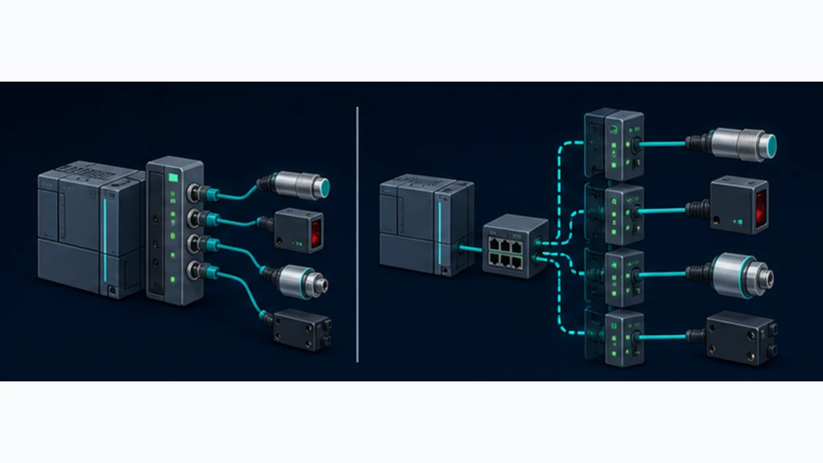
The S7-1200 G2 is a different hardware generation. Siemens states that S7-1200 G2 is not hardware-compatible with previous S7-1200 modules, so do not assume an SM 1278 can be attached to a G2 CPU. A current route can be a supported PROFINET distributed I/O station containing an IO-Link master, such as a compatible ET 200SP configuration, or another master whose PROFINET Device integration is approved for the exact G2 project. Verify the current TIA catalog, CPU firmware, interface module, IO-Link module and limits together.
The direct side-module and remote-master routes expose the same engineering chain: device and cable → IO-Link port → master → S7 process image → typed application value. They differ in physical compatibility, upstream network, power architecture, address allocation and diagnostic boundaries. Choose the architecture before importing IODDs.
This page owns the Siemens S7-1200 hardware selection, SM 1278, TIA Portal/S7-PCT, IODD, process-data mapping, parameter access, replacement and diagnostic task. The vendor-neutral IO-Link PLC guide retains protocol fundamentals, COM rates, data classes and cross-platform master selection. The S7-1200 programming guide retains general CPU, block, data and project structure. Use this specialist when those two subjects meet in one implementation.
Confirm the S7-1200 generation and architecture
Established S7-1200 with direct SM 1278
The SM 1278 is documented for the established SIMATIC S7-1200 family. Siemens' current industrial-control catalog describes four IO-Link V1.1 ports, SIO operation, COM1/COM2/COM3 transfer rates and configuration using TIA Portal with S7-PCT where required. The catalog lists a maximum 20 m master-to-device cable and up to 32 input bytes and 32 output bytes per port, but also lists a 32-byte input and 32-byte output ceiling for the module. Treat the module aggregate as the governing allocation and verify the exact firmware/manual rather than summing four per-port maxima into an unsupported total.
Depending on CPU type, Siemens' catalog states that up to eight SM 1278 modules can be used with an S7-1200. That headline is not the sole expansion check. CPU signal-module limits, available backplane current, address space, enclosure width, heat, device current and the complete project configuration still govern. Use TIA Selection Tool and the exact CPU/module manuals to validate a real rack.
| SM 1278 selection item | Current documented value or role | Project check |
|---|---|---|
| article number | 6ES7278-4BD32-0XB0 for standard SM 1278 4xIO-Link Master |
match installed label, hardware version and regional lifecycle |
| device links | four independent IO-Link master ports | one approved device per IO-Link port; no multidrop trunk |
| specification route | IO-Link V1.1 master with SIO support | match device/IODD revision and required optional behavior |
| communication rates | COM1, COM2 and COM3 supported | device negotiates its supported rate; do not force a rate as a timing shortcut |
| cable boundary | maximum 20 m per documented device link | check cable, connector, pinout, voltage drop and environment |
| process image | per-port capability plus module aggregate limits | allocate exact input/output lengths across all four ports |
| engineering | STEP 7/TIA Portal; S7-PCT depends on module/tool/feature path | freeze CPU, module firmware, TIA version, HSP and S7-PCT version |
| diagnostics | module DIAG and per-port status/error indicators plus software diagnostics | enable needed channel diagnostics and test each failure class |
S7-1200 G2 requires a different hardware route
Siemens explicitly says S7-1200 G2 is not hardware-compatible with previous-generation S7-1200 modules. The similarity of the controller name does not authorize an old side module. For a G2 project, select a master architecture from the currently supported G2/TIA catalog. A distributed ET 200SP station on PROFINET is one possible system pattern when its interface and IO-Link modules are supported by the exact CPU/TIA release.
In the distributed pattern, the S7-1200 G2 remains the PROFINET IO Controller. The ET 200 interface is a PROFINET IO Device, and its IO-Link communication module is the master for individual sensor/actuator ports. The controller sees configured module/process data over PROFINET; device identity, parameters, port events and replacement behavior still need their product-specific Siemens workflow.
Do not translate established SM 1278 limits to ET 200SP. For example, Siemens' current technical data for one ET 200SP CM 4xIO-Link product lists different aggregate input/output capacities, Port Class A/B behavior, backup capability and diagnostic options. Copy the exact values from the selected module's technical data and configuration, not from this S7-1200 side-module guide.
| Decision | Established S7-1200 + SM 1278 | Distributed PROFINET IO-Link master |
|---|---|---|
| best fit | compact cabinet and compatible established CPU | field distribution, G2-compatible route, more ports or different electrical needs |
| upstream boundary | S7 backplane/process image | PROFINET device, network name/IP, module slots and process image |
| principal configuration | CPU rack plus SM 1278 port/device configuration | PROFINET station/interface plus IO-Link module/ports/devices |
| failure domain | CPU-side module can affect four local ports | PROFINET, station power/interface and IO-Link module add layers |
| wiring | device cables return to PLC cabinet | remote master shortens field sensor runs but adds network and station power |
| limits to verify | CPU compatibility, module count, 32-byte aggregate images and port power | controller capacity, PROFINET update, interface/module limits, station power and port classes |
| G2 assumption | old module is not hardware-compatible | use only an exact currently supported station/module combination |
A CPU digital channel is not an IO-Link master
An IO-Link-capable sensor may offer Standard IO, or SIO, behavior on its C/Q line. In SIO mode it behaves as a conventional switching device, and an S7 digital input may read that switching state if the electrical interface is compatible. That does not provide cyclic multi-value process data, device identity, parameter indices, events, validation or automatic parameter restoration. Use SIO deliberately when one switch bit is the approved requirement; use an IO-Link master when IO-Link functions are required.
Design the physical ports and power before software
One device link per port
IO-Link is a point-to-point system. Each master port connects one device, commonly through an unshielded industrial sensor cable within the specified maximum length. There is no IO-Link node address to assign on a shared trunk. The master itself may sit on a backplane or upstream PROFINET network, but the field-device side remains separate links.
Record connector and pin functions for every port/device. Port Class A typically uses the primary supply and C/Q communication; Port Class B adds an auxiliary supply for devices or actuators that require it. The SM 1278 has its own documented terminal/power arrangement and must not inherit an M12 field-master pinout. Confirm device current, master per-port/total limits, inrush, protective response, cable conductor size and voltage at the device under worst load.
| Physical design field | Evidence | Failure if omitted |
|---|---|---|
| master and port identifier | module slot, port number and terminal/connector drawing | correct IODD is assigned to the wrong cable |
| device identity | manufacturer, order number, VendorID, DeviceID and revision | similar sensor is accepted with a different process-data layout |
| operating mode | IO-Link autostart/manual validation, DI/SIO, DQ/SIO or deactivated as supported | device link never starts or a conventional channel is interpreted as IO-Link |
| primary supply | voltage range, steady current, inrush and master protection | intermittent undervoltage or group trip appears as communication fault |
| auxiliary supply | class/product-specific requirement and safe isolation | actuator electronics communicate but load output cannot operate |
| cable | approved type, length, connector, routing and bend/environment limits | voltage drop, intermittent contact or EMC damage causes port faults |
| failure response | power loss, open/short, device mismatch and restoration behavior | stale process value remains accepted after a port failure |
Keep ordinary IO-Link separate from functional safety
Standard IO-Link process data, port qualifiers and diagnostic events are not a functional-safety communication channel. IO-Link Safety is a separate specification and product ecosystem. An ordinary SM 1278 map does not become safe I/O because the PLC is fail-safe or a device reports a diagnostic bit. Keep emergency stop, guard, safe speed and similar risk-reduction functions in their approved architecture unless exact certified components and a validated design explicitly provide the function.
Freeze the engineering versions and device files
TIA Portal, HSP and SM 1278 firmware form one compatibility set
Record the STEP 7/TIA Portal edition and update, CPU firmware, SM 1278 hardware/firmware, installed Hardware Support Package, S7-PCT version, LIOLink library version and every IODD file. Siemens' SM 1278 V2.1 product information describes an HSP for TIA Portal V15 and configuration without S7-PCT, while the S7-1200 manual distinguishes basic and advanced paths by STEP 7 and module version. Do not turn those historical minimums into a promise for every current project; check the compatibility matrix and release notes for the actual workstation.
S7-PCT can be launched from the supported device-tool entry in a TIA Portal project or used as a standalone tool in documented cases. The integrated route ties the port project to the PLC hardware configuration more clearly. If a migration requires export/import, preserve the PCT project and verify it after the TIA conversion instead of assuming all device parameters followed the PLC project.
| Controlled item | Why it matters | Archive evidence |
|---|---|---|
| CPU and module catalog/firmware | determines hardware support and features | online module information and released hardware configuration |
| TIA Portal edition/update | determines catalog, download and engineering behavior | installed-product inventory and project version |
| HSP | can add exact module/firmware support to a TIA release | package name/version and controlled installer source |
| S7-PCT | configures supported master ports and IO-Link devices | version, exported project/configuration and launch method |
| IODD | defines exact device identity, parameters and process-data structures | manufacturer/IODDfinder source, version and checksum |
| LIOLink library | implements approved acyclic or backup functions for listed masters | article/library version, block version and tested project copy |
| released map | connects master addresses to typed S7 tags | signed byte/bit table plus raw-value acceptance captures |
Match IODD identity rather than product appearance
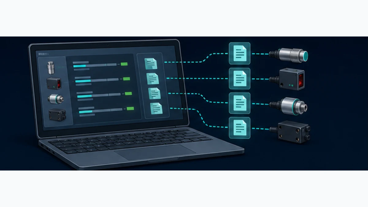
An IODD is the standardized IO Device Description for a specific device family/revision. It can describe VendorID, DeviceID, process-data variants, parameters, index/subindex access, events and presentation information. Obtain it from the device manufacturer or IODDfinder, verify the device identity and select the correct variant. Similar housings or family names can contain different layouts.
The IODD does not by itself prove the S7 byte address, scale or application validity. The master decides how configured port data is assembled into its upstream image; TIA Portal decides the assigned process addresses; the application decides how raw bits become a trusted engineering value. Retain all three layers.
Live mini-lab
Try it: press START, then STOP
A stop-dominant seal-in rung: START latches the motor output through its own contact, and STOP breaks the circuit.
Watch the output lamp: it stays on after START until you press STOP.
Free to start · runs in your browserOpens plcsimulationsoftware.com — same team
Configure SM 1278 in TIA Portal and S7-PCT
Add the exact hardware and allocate port lengths
Start from a backed-up project and a verified offline/online hardware inventory. Add the exact SM 1278 version in the S7-1200 device view. If it is absent, stop and resolve the TIA/HSP compatibility rather than substituting a visually similar module. Set the required module parameters, enable necessary port diagnostics and allocate input/output lengths for each port within the module totals.
The port lengths must match the selected device process-data variant. A sensor that produces 4 bytes on port 1 and a valve block that consumes 8 bytes on port 2 need an explicit allocation and offset record. Unused bytes can waste the small module image; undersized slots truncate data or prevent a valid configuration. Compile hardware after each controlled change and record final start addresses.
- Identify the established S7-1200 CPU, SM 1278 hardware/firmware and supported TIA/HSP combination.
- Insert the exact module in the device configuration and choose the released slot position.
- Enable the diagnostics required by the maintenance and alarm design.
- Allocate each port's process-data input and output lengths from the exact device variant.
- Verify the combined allocation remains within the module's input/output limits.
- Launch the supported integrated device tool or S7-PCT path.
- Import the exact IODD, assign one approved device to each port and set validation/data-storage policy.
- Configure only reviewed device parameters and record their source/default/released values.
- Save/export the PCT/device configuration and compile the complete TIA hardware project.
- Map assigned raw addresses into a dedicated interface DB or UDT; do not scatter
%Iand%Qreferences through machine logic.
Configure each port deliberately
A spare port should be deliberately deactivated or given the approved safe mode. A conventional sensor uses the supported DI/SIO mode; a conventional actuator uses DQ/SIO only within documented electrical limits. An IO-Link port can use automatic startup or explicit/manual identity rules depending on the module tool and project requirement. Stronger validation reduces wrong-device risk but can reject a service replacement whose identity/revision falls outside the policy.
Data storage and replacement behavior require direction. Decide whether the master uploads from an approved device, downloads a stored set to a replacement, or blocks on mismatch. Protect the commissioning master from learning an unintended field adjustment as the new baseline. Record identity and parameter comparison before enabling automatic restoration.
| Port decision | Configuration evidence | Acceptance stimulus |
|---|---|---|
| mode | exact IO-Link, SIO input/output or disabled setting | connect intended device and one controlled wrong-mode case |
| validation | VendorID/DeviceID/revision policy | substitute an unapproved identity and prove rejection/diagnostic behavior |
| process variant | IODD variant and byte/bit lengths | stimulate every field and compare raw data |
| data storage | upload/download/disable authority and master capacity | controlled replacement with known parameter difference |
| events | enabled diagnostic path and alarm mapping | create a harmless documented warning/fault condition |
| substitute behavior | master/PLC reaction to loss or invalid quality | unplug device in a safe state and prove consumer response |
Map process data into typed S7 variables
Decode raw bytes with a signed contract
Create a mapping sheet for each master port: TIA input/output start address, IODD process-data variant, bit offset/length, byte order, signedness, scale, unit, value-status/port qualifier, valid range, invalid behavior and owner. Do not infer a universal IO-Link endian rule from another device. The device's IODD/manual defines its process field; the master/module defines how it appears upstream.
Use asymmetric raw patterns to reveal byte swaps and bit mistakes. For a measurement, apply a low nonzero point, midpoint, high point and any relevant negative value. Capture the device display/reference, raw S7 bytes, intermediate integer, scaled value and quality state. For a packed status byte, stimulate each independent flag while confirming adjacent bits do not change unexpectedly.
| Mapping field | Example—not a universal SM 1278 layout | Acceptance proof |
|---|---|---|
| master/port | rack slot 4, port 2 | physical label and online port identity agree |
| TIA range | input bytes assigned by released module configuration | watch table captures exact raw bytes without overlap |
| device field | 16-bit signed measurement plus status flags | selected IODD variant names identical fields and lengths |
| byte/bit order | documented high/low-byte or bit offset interpretation | asymmetric patterns decode correctly |
| scale/unit | device-documented factor and engineering unit | calibrated or trusted reference agrees at test points |
| quality | Extended Port Qualifier/value status or supported diagnostic representation | link loss and device invalid state both reject application value |
| fallback | application-specific substitute or hold rule with alarm | injected invalid state produces reviewed machine behavior |
| revision | map version tied to IODD and module project | incompatible version cannot silently enable commands |
Separate transport quality from process validity
A healthy SM 1278 module does not prove that every port is communicating. A communicating port does not prove that a process value is valid. A valid device value may still be outside the machine's plausible operating range. Carry module health, port communication/diagnostic state, device value status and application plausibility separately.
A vendor-neutral SCL-style consumer pattern illustrates the layers:
ModuleOK := NOT MasterModuleFault;
PortOK := PortCommunicationActive AND NOT PortDiagnosticFault;
DeviceDataOK := PortQualifierGood AND DeviceValueStatusGood;
Plausible := RawScaledValue >= EngineeringMinimum
          AND RawScaledValue <= EngineeringMaximum;

Measurement.Valid := ModuleOK AND PortOK AND DeviceDataOK AND Plausible;

IF Measurement.Valid THEN
    Measurement.Value := RawScaledValue;
    Measurement.Age := T#0ms;
ELSE
    Measurement.Age := Measurement.Age + TaskElapsed;
    Measurement.Value := DefinedFallback;
END_IF;
Run Structured Text in the simulator
The actual diagnostic tags and qualifier encoding depend on the module/firmware and configuration. Use symbolic tags generated by the released project where available and preserve raw diagnostic status for first-fault analysis.
Read and write acyclic device parameters safely
Use the approved LIOLink library and exact master list
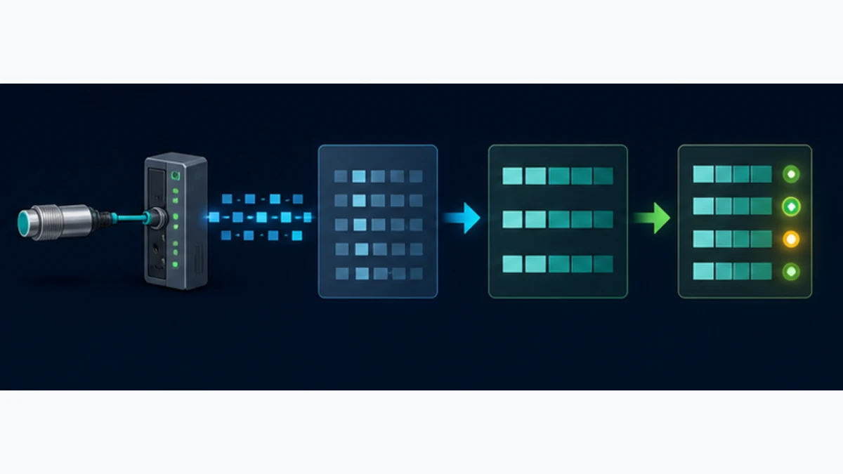
IO-Link process data is cyclic; device identity and configurable parameters are commonly accessed through acyclic index/subindex services. Siemens' LIOLink V7 library documents blocks for approved Siemens masters, including the established S7-1200 SM 1278 at specified firmware. LIOLink_Device provides device access, while LIOLink_Master is documented for master backup/restore functions. Confirm the current library documentation and master firmware list before using either block.
Treat the blocks as asynchronous state machines. Supply the exact hardware identifier/logical address, port, index, subindex, length and record buffer defined for the chosen block version. Trigger one request according to the interface rules; retain busy, done, error, status and diagnostic outputs. Do not continuously assert an execute input, overlap writes to the same port or accept a done edge without reading back the parameter where verification is required.
| Acyclic operation | Preconditions | Completion proof |
|---|---|---|
| identity read | correct master/port online and supported block instance | returned VendorID/DeviceID/serial data matches released record |
| parameter read | index/subindex, access type and expected length from exact IODD | returned length/type/value decoded and range-checked |
| parameter write | controlled machine state, approved value and access rights | block completes, value is read back and device behavior is functionally tested |
| recipe download | exact device identity and released parameter set | every write/result is logged; final comparison and first-piece/process test pass |
| device data-storage restore | compatible IO-Link V1.1 device and configured authority | replacement receives intended set and passes comparison/functional test |
| master backup/restore | exact supported Siemens master/library/firmware | backup length/status retained; restore to representative spare is proved |
Make parameter writes controlled changes
A parameter can change a switching point, filter, output logic, measurement range or device behavior. Apply access control, audit identity, require an approved operating state and validate the result. Do not let an HMI numeric field write arbitrary index/subindex values directly. Expose only reviewed recipes or bounded parameters with units, limits and confirmation.
Separate a service request from a process command. Queue writes, serialize access per master as the library requires, use timeouts based on documented behavior and preserve the first status code. A failed write must not leave the HMI showing an optimistic requested value as though it were confirmed.
Commission and validate the complete chain
Prove identity before value
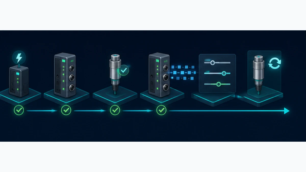
Commission with machine energy in an approved safe state. Record baselines before downloads. Prove the module, then each port identity, then raw process data, then decoded engineering meaning, then acyclic access, events, loss and replacement. Enabling the final actuator or using a measurement in a permissive belongs at the end.
- Archive the TIA project, PCT configuration, IODDs, HSP, LIOLink library and exact device parameter sets.
- Record CPU/module/device order numbers, firmware, tool versions, cable/port assignments and supply measurements.
- Compile and download the approved hardware configuration with field commands inhibited.
- Verify module DIAG and every port's status/error indication against the manual.
- Connect one device; compare online VendorID, DeviceID, revision, process length and selected IODD.
- Stimulate known raw patterns and prove byte order, bit positions, sign, scaling, unit and value status.
- Read a harmless known parameter through the approved acyclic block and compare it with the device configuration.
- Perform one controlled bounded parameter write, read it back, functionally test it and restore the baseline if the test requires.
- Create a documented device event and confirm the master, PLC diagnostic and intended HMI/maintenance path.
- Break the device link safely and verify port diagnostics, data invalidation, fallback, first fault and recovery behavior.
- Replace the device with an approved spare and prove validation, parameter restoration and complete functional acceptance.
- Repeat under representative PLC task, PROFINET if used, master and device load; then release the application and safety validation.
| Test case | Stimulus | Evidence to retain | Rejection condition |
|---|---|---|---|
| correct device startup | connect released device to released port | identity, mode, COM rate, lengths, good status and expected data | autostart hides a different identity or process variant |
| wrong device | connect controlled incompatible spare | validation diagnostic and rejected/invalid application value | plausible bytes are accepted from the wrong product |
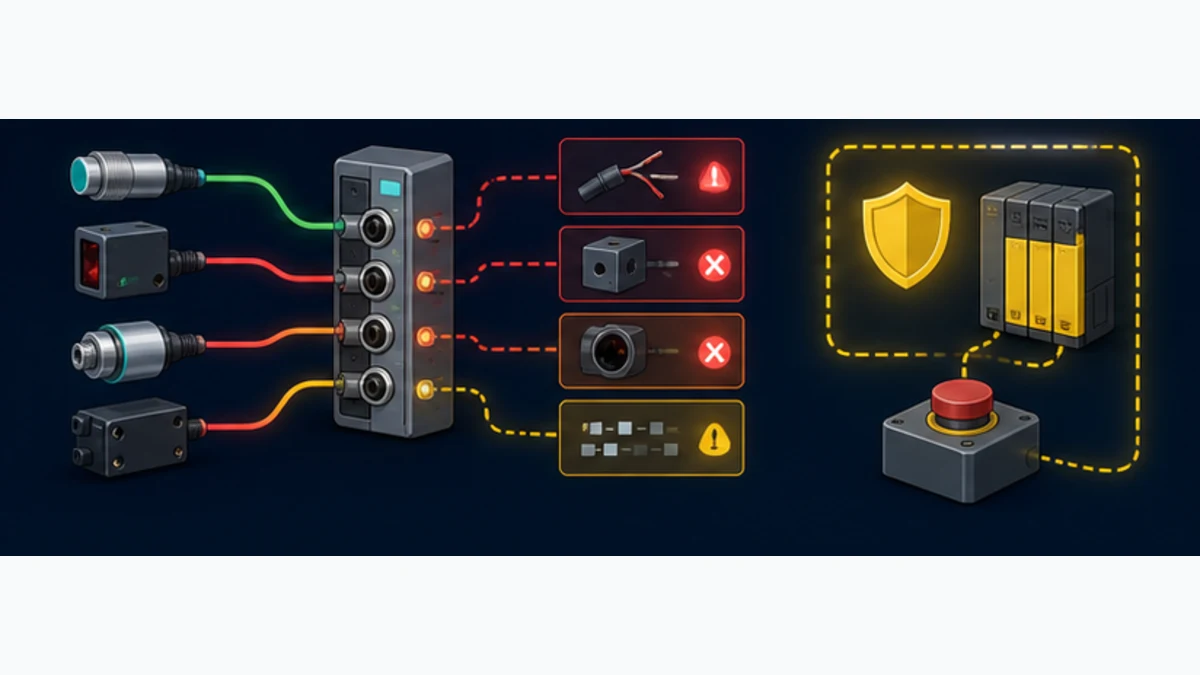
| open circuit | disconnect device in safe state | port/module diagnostic, invalid data, alarm, timestamp and fallback | last value remains usable without stale/invalid state |
| short/overload | use approved test method or simulator, not an unsafe short | protective/diagnostic response and affected-port scope | uncontrolled group loss or undocumented recovery |
| raw decode | apply asymmetric low/mid/high/negative patterns as relevant | raw bytes, intermediate type, scale, unit and reference | only one convenient value was checked |
| parameter write | change one bounded lab parameter | request, completion status, readback and functional result | HMI requested value is mistaken for confirmed device state |
| event path | create harmless supported warning/event | device, PCT/master, PLC and HMI evidence share one timestamp order | event is visible only in engineering laptop |
| replacement | install approved spare with known different baseline | validation, restore direction, final comparison and functional result | communication return alone counts as acceptance |
Diagnose faults from the device toward the PLC
Preserve the first failing boundary
Start at the physical process and device indication. Continue through cable/connector and supply, master port LED/diagnostic, module diagnostics, TIA hardware state, raw process bytes, qualifier/value status, decode and application logic. Capture evidence before resetting or replacing. Several later alarms can be consequences of one supply or cable fault.
For the SM 1278, Siemens documents DIAG for module state, C indicators for port communication, Q indicators for channel state and F indicators for port errors. Interpret colors and flashing patterns from the exact module manual; do not generalize a screenshot from another firmware or ET 200 product. Software diagnostics should identify the port and category more precisely than a cabinet LED.
| Symptom | First discriminating evidence | Likely layer | Next controlled action |
|---|---|---|---|
| module absent in TIA online view | catalog object, slot, HSP, module identity and backplane state | hardware/tool compatibility | compare installed label to released project; resolve exact TIA/HSP support |
| module DIAG fault | detailed module/channel diagnostic and supply | module configuration/power | retain diagnostic code; verify voltage, module parameters and exact manual |
| one port has F indication | port diagnostic, device supply and connector | device link/port | compare port mode and identity; inspect cable and substitute known-good components |
| communication active but value wrong | raw bytes, IODD variant and map version | process-data decode | apply asymmetric patterns; verify offset, length, byte order, sign and scale |
| value freezes after disconnect | qualifier/status and application age behavior | invalid-data handling | break link again in safe state and prove value rejection/fallback |
| device mismatch after replacement | online VendorID/DeviceID/revision and validation policy | identity/replacement | install approved device or deliberately update released policy and retest |
| parameter read/write errors | block status/diagnostics, index/subindex, port and record length | acyclic service/application | decode exact status from library/device docs; read harmless identity first |
| restore loads wrong settings | data-storage direction, master store and device baseline | configuration governance | stop, restore released set, compare every governed parameter and functionally test |
| several remote ports fail | PROFINET station/network and station power before individual sensors | upstream distributed architecture | preserve station/module diagnostics and network evidence |
Do not diagnose timing from COM rate alone
COM1, COM2 and COM3 are device-link bit rates, not end-to-end PLC response guarantees. Device minimum cycle time, process-data length, master scheduling, backplane or PROFINET update, S7 task period, phase alignment, diagnostic/acyclic activity and application filtering all contribute. Measure a sequence or process transition at the producing device and the consuming S7 application under representative load.
Use cyclic process data for time-sensitive routine values. Acyclic parameter requests can span multiple calls/cycles and should not drive a fast control loop. If response time affects machinery integrity, use the exact device/master timing data and a representative acceptance test.
Design replacement, security and lifecycle controls
Replacement is an identity and configuration transaction
An IO-Link V1.1 master may support data storage for compatible devices, but “automatic replacement” is not a universal plug-and-play promise. Define acceptable VendorID, DeviceID and revision policy, master/device upload/download authority, stored parameter baseline, capacity and behavior when the replacement is blank, newer or already configured. Preserve a manual recovery path.
The acceptance finish is not a green C port LED. Compare identity, restored parameters, process-data variant, raw/scaled values, diagnostic behavior and the machine function. For measurement devices, apply the required calibration/verification procedure. For actuators, prove safe state, commands, feedback and recovery in a controlled test.
Treat parameter access as an OT change surface
IO-Link does not define the complete plant cybersecurity architecture. The S7 project, engineering workstation, PCT files, master web interface if present and HMI parameter features can change field behavior. Apply least privilege, approved engineering paths, controlled remote access, backups, audit records and vendor advisories. Disable unnecessary services on distributed masters and segment the upstream PROFINET network according to the site design.
| Lifecycle control | Evidence | Failure prevented |
|---|---|---|
| approved device list | exact identities, IODDs, firmware/revision policy and alternatives | uncontrolled substitution changes data layout or behavior |
| parameter baseline | exported/read-back set, owner, checksum/comparison and release record | master restores an unknown or stale configuration |
| project recovery set | TIA, PCT, HSP, IODDs, libraries, licenses and tool versions | spare hardware cannot be commissioned after laptop loss |
| access control | named roles and bounded HMI/engineering parameter operations | unauthorized or accidental field-setting change |
| diagnostics retention | first port/module code, device event and time-aligned PLC alarm | reset erases the evidence needed to prevent recurrence |
| spare acceptance | bench identity, compatibility, restore and functional test | nominally similar replacement fails during outage |
Frequently asked questions
Does the Siemens S7-1200 support IO-Link?
Yes, through a compatible IO-Link master. Siemens lists the SM 1278 4xIO-Link Master for the established S7-1200 hardware generation. The S7-1200 G2 is not hardware-compatible with previous S7-1200 modules, so select a currently supported G2/distributed master architecture instead of assuming the SM 1278 attaches.
What is the Siemens SM 1278 IO-Link master?
The SM 1278, article number 6ES7278-4BD32-0XB0, is a four-port IO-Link V1.1 signal module for the established S7-1200 family. It exchanges IO-Link device data through individual point-to-point ports and maps configured input/output data into the S7 process image. Verify firmware, tool, image and power limits for the installed unit.
Can an IO-Link sensor connect directly to an S7-1200 digital input?
Only its conventional SIO switching function can be used that way when the sensor and circuit support it. A digital input is not an IO-Link master and cannot provide IO-Link identity, structured process data, parameters, events or data-storage replacement. Use a compatible master for those functions.
Can the S7-1200 G2 use an SM 1278 module?
Do not assume so. Siemens states that S7-1200 G2 is not hardware-compatible with previous-generation S7-1200 modules. Use a master solution explicitly supported for the exact G2 CPU and TIA release, such as a validated distributed PROFINET IO-Link station where appropriate.
Is S7-PCT always required for SM 1278 configuration?
It depends on SM 1278 firmware, TIA Portal version, installed HSP and the required features. Siemens documentation distinguishes configurations where basic functions can be engineered without S7-PCT from advanced or older-version paths that use it. Freeze and verify the exact compatibility set rather than applying one universal instruction.
How is an IODD used in TIA Portal for S7-1200 IO-Link?
The exact IODD is imported into the supported IO-Link engineering workflow, commonly S7-PCT or a compatible integrated device tool, and assigned to the master port. It supplies device identity, process-data and parameter definitions. TIA hardware addresses and the PLC mapping contract still determine where and how those fields are consumed.
How do I map SM 1278 process data into S7-1200 tags?
Allocate each port's input/output length in the released hardware/device configuration, record the resulting TIA addresses, then decode the exact IODD fields into a dedicated typed DB or UDT. Prove bit offset, byte order, sign, scale, units and qualifier/value status with asymmetric test patterns.
How can an S7-1200 read and write IO-Link parameters?
Use a Siemens-supported acyclic integration for the exact master, such as the current LIOLink library where its approved-device list includes the installed SM 1278 firmware. Supply the documented port/index/subindex and record buffer, execute the asynchronous request, retain status/diagnostics and read back controlled writes.
Why is an SM 1278 port communicating but the PLC value is wrong?
Check the selected device identity and IODD process-data variant, configured port length, TIA address, byte/bit offset, order, sign, scale and value status. Apply several known asymmetric values and compare raw bytes at each boundary; a green port only proves communication, not correct interpretation.
Is ordinary S7-1200 IO-Link data safety rated?
No. Standard IO-Link mapped through an ordinary SM 1278 is not a functional-safety channel. IO-Link Safety is a separate specification and requires certified compatible components and a validated safety lifecycle. Keep ordinary diagnostics and control data outside the credited PL/SIL function unless the exact approved architecture states otherwise.
Practical next step
Photograph the CPU and candidate master labels, then write one architecture line: established S7-1200 + compatible SM 1278, or S7-1200/G2 PROFINET Controller + exact distributed IO-Link master. Freeze the CPU/module firmware and TIA/HSP/PCT versions, choose one real sensor/IODD, allocate its bytes and run the identity-to-replacement acceptance chain before scaling to every port.
Sources, review scope and limitations
This guide was reviewed on August 30, 2026. Product and software support changes by region, lifecycle, hardware generation, firmware, TIA version and installed support package. The cited material establishes current documented routes and concepts; only the approved project, exact manuals and representative hardware prove an installation.
- Siemens, 2025 industrial-control catalog: SM 1278 4xIO-Link Master overview, functions, limits and ordering data.
- Siemens Industry Mall, SM 1278 4xIO-Link Master product family.
- Siemens, S7-1200 system manual with SM 1278 configuration and address space.
- Siemens, SM 1278 firmware V2.1 product information and HSP/configuration notes.
- Siemens, S7-1200 G2 system manual V4.1.
- Siemens, S7-1200 G2 product FAQ and previous-module compatibility boundary.
- Siemens, SIMATIC IO-Link system function manual, May 2024.
- Siemens, LIOLink library V7 manual: device access and master backup/restore.
- Siemens Industry Online Support, Library for IO-Link download article 82981502.
- Siemens Industry Online Support, S7-PCT Port Configuration Tool article 32469496.
- Siemens Industry Mall, ET 200SP CM 4xIO-Link technical data example.
- Siemens Industry Mall, ET 200eco PN IO-Link master technical data example.
- IO-Link Community, IO-Link Interface and System Specification V1.1.4.
- IO-Link Community, IO-Link System Description.
- IO-Link Community, current specifications, profiles, integration and test downloads.
- IODDfinder, manufacturer-submitted IO Device Description database.
- IEC, IEC 61131-9 single-drop digital communication interface publication.
- IO-Link Community, IO-Link Safety system description.
Now run it · free to start
Follow plant data from sensor to SCADA
Fieldbus versus Ethernet, Modbus, EtherNet/IP, PROFINET, OPC UA and MQTT, then SCADA layers and alarms, taught on simulated equipment. Free to start.
Ownership disclosure: PLC Programming IO and PLC Simulation Software are operated by the same publisher.
PLC Programming IO Editorial Team
Industrial automation education, references, and software testing
The PLC Programming IO Editorial Team publishes sourced industrial-automation education and documents how material is reviewed, tested, and corrected. A team byline means the publisher is responsible for the page; it does not represent a fictional person or imply an engineering licence.
Coverage:
- • PLC programming concepts and examples
- • Vendor software tutorials and comparisons
- • SCADA, HMI, protocols, and instrumentation
- • Training, careers, and reference material
Review standard:
- • Prefer primary and official sources
- • Record software versions when material
- • Separate tested facts from estimates
- • Publish material corrections
Important scope note
This site provides education, not project-specific engineering approval. Safety, code, and compliance decisions require a qualified person with access to the actual machine and jurisdiction.