CompactLogix Programming Guide: 5380 Setup & Selection
Plan and program a CompactLogix 5380 system from controller and 5069 I/O selection through Studio 5000 tasks, tags, routines, testing and commissioning.
CompactLogix 5380 is Rockwell Automation's Logix-family controller platform for machine and plant applications that need Studio 5000 programming, EtherNet/IP connectivity and scalable local I/O. A good project begins with capacity and architecture—not a catalog number—then separates physical I/O, equipment modules, sequences, alarms and HMI commands into testable layers.
Download the CompactLogix architecture worksheet (CSV)
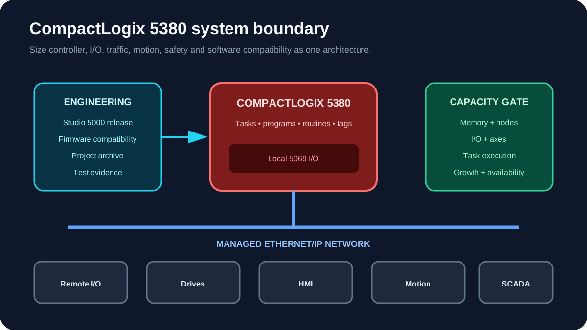
CompactLogix selection checklist
| Capacity area | Question to answer | Evidence |
|---|---|---|
| Application | Machine, skid, line cell or small process area? | Control narrative and architecture drawing |
| I/O | Local and remote point count, module mix, spare plan? | Approved I/O list |
| EtherNet/IP | How many devices and what traffic pattern? | Network schedule and requested packet intervals |
| Motion | How many integrated axes and what update needs? | Motion design |
| Safety | Standard or Compact GuardLogix? | Risk assessment and safety requirements |
| Memory | Program, tag, alarm, recipe and growth allowance? | Estimate from comparable validated project |
| Availability | Can one controller or network path meet the requirement? | Availability study |
| Software | Which firmware and Studio 5000 release are approved? | Rockwell compatibility record |
Rockwell's current CompactLogix 5380 product page links the 1769-SG003 selection guide, 5069-TD002 specifications and 5069-UM001 user manual. Use those documents for the exact model instead of copying a capacity figure from a reseller page.
CompactLogix, Compact GuardLogix and ControlLogix
- CompactLogix 5380 fits many standalone machines, skids and line cells.
- Compact GuardLogix 5380 adds an integrated safety option. It does not remove the need for safety requirements, verification and validation.
- ControlLogix 5580 uses the modular 1756 chassis ecosystem and is commonly selected when architecture, capacity, module range, high-performance motion or plant-level requirements justify it.
Choose from requirements. “We always use the biggest PLC” increases cost and spares complexity; “this machine is small” can underestimate network, motion or data requirements.
1. Freeze the hardware identity
Record:
- exact controller catalog number and series;
- firmware revision;
- Studio 5000 Logix Designer version;
- local 5069 module catalog numbers and positions;
- network addresses and device names;
- SD-card and security requirements;
- safety signature and locked/unlocked state where applicable.
Firmware and software compatibility must be checked in Rockwell's Product Compatibility and Download Center. Do not flash firmware simply because a newer revision exists; confirm the plant lifecycle and validated-version policy.
Live mini-lab
Try it: press START, then STOP
A stop-dominant seal-in rung: START latches the motor output through its own contact, and STOP breaks the circuit.
Watch the output lamp: it stays on after START until you press STOP.
Free to start · runs in your browserOpens plcsimulationsoftware.com — same team
2. Create the Studio 5000 project
Create a new project with the exact controller and revision. Configure the controller name, chassis/local I/O and Ethernet ports from the approved network design.
Then establish conventions before adding logic:
Area_Equipment_Signal
PKG01_CV01_RunCmd
PKG01_CV01_RunFb
PKG01_CV01_Faulted
PKG01_PE101_Blocked
Use Add-On Instructions only where a stable, reusable interface justifies the lifecycle burden. A copied routine is easy to edit; an AOI instance is easy to deploy consistently but changes can affect many consumers.
3. Separate physical I/O from equipment logic
Create mapping routines:
Local:1:I.Data.0  →  Raw.PB_Start
Local:1:I.Data.1  →  Raw.StopCircuitHealthy
Raw.PB_Start      →  Cmd.StartPB
Logic.RunOutput   →  Raw.MotorStarter
Raw.MotorStarter →  Local:2:O.Data.0
This creates one place to:
- invert normally-closed field logic;
- scale and alarm analog inputs;
- simulate field points;
- migrate modules;
- enforce output defaults;
- explain the relationship between the electrical drawing and program.
4. Design tasks deliberately
Logix tasks determine when programs execute.
Continuous task
Useful for ordinary machine logic where the controller executes repeatedly when higher-priority work is not running.
Periodic task
Useful when an algorithm needs a defined execution interval—for example a control loop, motion coordination or deterministic calculation. The chosen period must reflect process dynamics and total execution load.
Event task
Useful for specific supported events when justified by the design. Do not use event tasks merely to make logic feel “faster.”
For each task, document priority, period or trigger, watchdog and programs. Check task overlap and execution time online under representative load.
5. Use equipment modules with explicit states
A conveyor module should expose an interface rather than scatter bits across routines:
| Group | Example members |
|---|---|
| Commands | Start, Stop, Reset, AutoRequest |
| Permissives | SafetyOK, DriveReady, DownstreamReady |
| Status | Running, Stopped, Starting, Faulted |
| Alarms | StartFail, Jam, DriveFault, SafetyTrip |
| Configuration | StartTimeout, StopTimeout, JamDelay |
Use a state model:
STOPPED → STARTING → RUNNING → STOPPING → STOPPED
               ↘ FAULTED ↗
State ownership prevents contradictory commands and makes abnormal behaviour testable.
6. First-project example: conveyor
Requirements:
- Conveyor starts in Auto when the upstream request is true and downstream is ready.
- It stops if downstream becomes unavailable.
- A jam sensor persisting for two seconds trips the conveyor.
- Run feedback must arrive within three seconds.
- Reset is accepted only when the trip condition is clear.
Implementation layers:
MapInputs: reads pushbuttons, status and sensors.ModeManager: owns Off/Manual/Auto.Conveyor: owns state, permissives, commands and alarms.Sequence: issues the Auto request.MapOutputs: writes the starter/drive command.AlarmSummary: exposes actionable messages to the HMI.
Test at least: normal start, missing downstream permissive, run-feedback failure, jam during start, jam while running, reset with jam present, Auto-to-Manual transfer and controller restart.
7. EtherNet/IP architecture rules
- Use managed industrial switches where diagnostics, segmentation or redundancy require them.
- Document every IP address, device name, connection owner and requested packet interval.
- Separate control design from enterprise connectivity through the site's approved architecture.
- Check multicast/unicast behaviour and switch features for the actual device set.
- Avoid daisy chains that create an unacceptable single point of failure.
- Baseline port errors and connection diagnostics at commissioning.
The number of devices is only one constraint. Traffic, packet rates, motion, HMI polling and produced/consumed tags can matter before a nominal node limit is reached.
8. Download and commission
Offline gate
- Project compiles without unexplained warnings.
- I/O tree matches approved hardware.
- Controller and module keying are intentional.
- Network settings match the schedule.
- Outputs and retained values have reviewed startup behaviour.
- Test cases have expected results.
Online gate
- Identify the controller by catalog number, serial/identity and network path.
- Upload and archive the running project if this is not a new controller.
- Compare offline and online projects.
- Download under an approved machine state.
- Verify controller mode and major/minor faults.
- Check inputs before commanding outputs.
- Remove all forces and temporary bypasses.
- Save the final project and commissioning evidence.
Troubleshooting table
| Symptom | Check first |
|---|---|
| Yellow triangle on I/O | catalog number, revision, keying, connection and power |
| Module data not updating | connection status, inhibit state, ownership and network |
| Scan or task watchdog problem | task period, execution time, loops and competing priorities |
| HMI cannot write | tag access, external access, security and command handshake |
| Drive drops connection | physical errors, RPI, topology, switch diagnostics and duplication |
| Program starts unexpectedly | retained values, first-scan logic, mode transfer and HMI command latching |
Primary references
- Rockwell Automation, CompactLogix 5380 controllers and documentation index.
- Rockwell publications referenced there: 1769-SG003 selection guide, 5069-TD002 specifications and 5069-UM001 user manual.
- Rockwell Automation, Product Compatibility and Download Center, for the exact controller firmware and Studio 5000 combination.
Related guides
Now run it · free to start
Practise Allen-Bradley-style logic in your browser
Work XIC, XIO, OTE, TON and CTU logic without a Studio 5000 licence. An independent learning tool — free to start, no install.
Ownership disclosure: PLC Programming IO and PLC Simulation Software are operated by the same publisher.


