PLC Block Diagram: CPU, I/O, Memory & Scan Flow
Read a PLC block diagram from field inputs through modules, CPU, memory, communications and outputs. Includes scan flow, architecture variants and a planning worksheet.
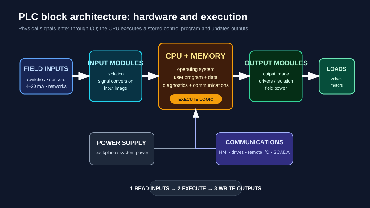
A PLC block diagram shows how field inputs pass through input modules to the CPU, how the CPU executes a program stored in memory, and how calculated states pass through output modules to actuators. Power, communications, diagnostics and engineering software surround that core input–process–output path.
The diagram is conceptual. The exact backplane, terminal, power and memory arrangement depends on the controller family. Use it to understand ownership and data flow, then use the current manual for the selected hardware.
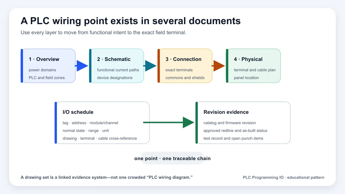
“PLC diagram” can mean several different documents. A block diagram explains functional ownership and data flow; it does not replace a wiring schematic, I/O schedule, panel layout, network topology, P&ID, ladder program or safety drawing.
Download the PLC architecture planning worksheet (CSV)
Which PLC diagram do you need?
| Diagram or artifact | Main question answered | Contains | Must not be inferred from it |
|---|---|---|---|
| functional block diagram | what major components exchange power, signals and data? | CPU, memory, I/O, communications and system boundaries | terminal numbers, conductor protection or exact execution timing |
| electrical schematic/wiring diagram | how does current flow through a specific circuit? | terminals, commons, contacts, coils, supplies and references | program behavior or process intent |
| I/O list and point map | which field point maps to which channel and software object? | tag, address, signal type, range, fail state and drawing reference | complete circuit or control narrative |
| network topology | how are communicating devices physically/logically connected? | ports, media, nodes, zones, roles and redundancy | application data meaning or safe loss response |
| P&ID or process diagram | what process equipment and instrumentation interact? | equipment, pipes, instruments, loop tags and process flow | PLC terminal wiring or exact program implementation |
| ladder/FBD/ST program | how does the controller compute states and commands? | executable or target-specific logic | physical proof that a device moved |
| cause-and-effect / control narrative | what behavior is required for operating and abnormal states? | modes, permissives, trips, responses and reset authority | exact code or circuit design |
| safety lifecycle drawings | how is claimed risk reduction implemented and validated? | approved safety functions, architecture and proof evidence | ordinary PLC logic as a substitute |
Start with the question, then select the artifact. During troubleshooting, correlate at least the process, electrical, I/O-map, online-program and physical-feedback views. A single diagram rarely proves the whole path.
PLC block diagram at a glance
| Block | Primary job | Design evidence | Common failure |
|---|---|---|---|
| Power supply | Provide controller/backplane power | power budget and supply specification | undervoltage, overload, wrong grounding |
| CPU | Execute tasks, communications and diagnostics | exact catalog/firmware and execution estimate | watchdog, major fault, overload |
| Memory | Store program, tags, configuration and retained data | memory estimate and retention plan | capacity exhaustion, stale retained state |
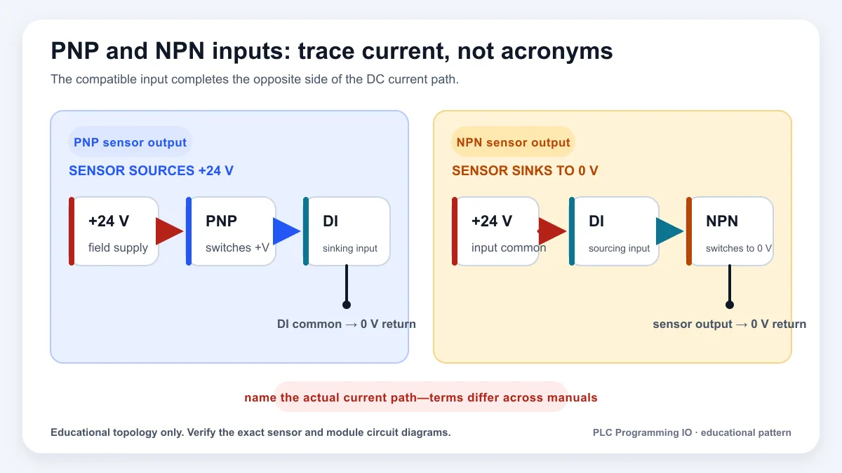
| Input modules | Isolate and convert field signals into controller data | I/O list and module wiring diagram | wrong common, channel mode or scaling |
| Output modules | Convert controller decisions into field switching/signals | load schedule and output rating | inrush, short circuit, leakage or wrong voltage |
| Communications | Exchange data with I/O, HMI, drives and other controllers | network architecture and message ownership | duplicate address, loss, stale data |
| Engineering interface | Configure, download, monitor and archive | approved software/version and backup | wrong project/revision or uncontrolled online edit |
1. Power-supply block
A PLC needs a compatible power source for the CPU and system bus. Some compact controllers contain an integrated supply; modular systems may use a dedicated chassis or bus supply. Field devices and output loads often need separate power even when their modules receive backplane power.
The block diagram should distinguish:
- incoming mains or 24 VDC;
- controller/backplane power;
- field input power;
- output/load power;
- isolated supplies and commons;
- protective earth and functional-earth connections;
- redundancy, UPS or hold-up requirements.
Do not infer terminal wiring from a block arrow. Verify conductor protection, isolation, inrush, permissible supply range and grounding in the exact product documentation.
2. CPU block
The CPU contains the processor and system functions that schedule logic, handle communications, update I/O, diagnose faults and manage memory. A “faster CPU” is not automatically a better design. Selection should start with the required I/O, tasks, motion, safety, network nodes, data handling, execution time and lifecycle.
CPU behavior is organized differently across platforms:
- a small PLC may expose one cyclic program;
- IEC 61131-3 systems may use tasks and program organization units;
- Siemens projects use organization blocks, function blocks, functions and data blocks;
- Logix controllers use tasks, programs and routines.
The block remains the same even when the software vocabulary changes: a scheduler decides what logic executes, when it executes and what happens if execution exceeds its limit.
3. Memory block
PLC memory is not one generic bucket. A design may include:
- nonvolatile project and firmware storage;
- working memory for logic and data;
- input and output process images;
- retained or retentive values;
- diagnostics and fault history;
- recipe, alarm, historian-buffer or communication data;
- removable media for backup or transfer.
Retention needs deliberate ownership. A production count may need to survive power loss; a momentary start request usually should not. After a restart, the program should establish a defined state rather than allowing every old Boolean value to resume unquestioned.
4. Input-module block
Input modules translate field conditions into data the CPU can use.
Digital inputs
A digital input detects an on/off electrical state. The module still needs the correct voltage family, sourcing/sinking arrangement, common, input delay and wiring protection. A physically normally closed contact does not guarantee the PLC Boolean is false in the healthy state; document the electrical and logical conventions separately.
Analog inputs
An analog input converts current, voltage, resistance or another measured signal into a numeric value. Configuration covers channel mode, range, filtering, raw counts, engineering scaling, open-circuit behavior and diagnostics.
Specialty and network inputs
High-speed counters, motion feedback, thermocouple, RTD and safety modules may process signals differently from ordinary cyclic I/O. Remote I/O adds network update behavior, connection status and stale-data handling.
5. CPU scan and process images
A simplified cyclic scan is:
- read physical inputs or update the input image;
- execute scheduled program logic;
- write the output image to physical outputs;
- perform communications, diagnostics and housekeeping;
- repeat.
That sequence is a learning model, not a universal timing promise. Some platforms update modules asynchronously, use immediate I/O instructions, schedule periodic/event tasks or exchange network data independently of the continuous task.
The design question is therefore not only “what is the scan time?” It is:
- when is each value produced;
- when is it consumed;
- how old may it be;
- what indicates valid/invalid data;
- which task owns the output;
- what happens on communication loss or task overrun?
6. Output-module block
Output modules convert controller state into electrical action.
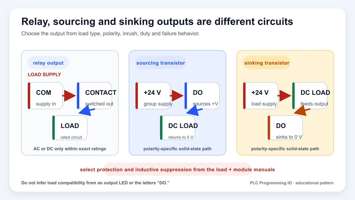
| Output type | Typical role | Critical check |
|---|---|---|
| Relay | AC/DC switching with physical contact isolation | contact voltage, current, inrush and life |
| Transistor | Fast DC switching | sourcing/sinking type, leakage and inductive suppression |
| Triac | AC switching | leakage, minimum load and zero-cross behavior |
| Analog current | 4–20 mA command | loop power, burden, fail direction and scaling |
| Analog voltage | 0–10 V or similar | reference/common, impedance and noise |
| Network command | drive, valve island or remote output | connection status, ownership and timeout state |
An output command is not a safety function merely because logic turns it off. Safety-related risk reduction requires the approved architecture, components and validation process.
Live mini-lab
Try it: press START, then STOP
A stop-dominant seal-in rung: START latches the motor output through its own contact, and STOP breaks the circuit.
Watch the output lamp: it stays on after START until you press STOP.
Free · no signup to try · runs in your browserOpens plcsimulationsoftware.com — same team
7. Communications block
Communications connect the controller to remote I/O, HMIs, drives, robots, vision systems, SCADA, historians and other controllers. The block diagram should show more than a protocol name.
Record:
- physical port and medium;
- device/connection owner;
- producer and consumer;
- cyclic rate or requested update;
- command/status handshake;
- data validity and heartbeat;
- timeout and fallback behavior;
- security zone and routed boundaries;
- diagnostic location.
A network arrow without ownership creates hidden coupling. A useful block labels who commands, who acknowledges and what both sides do when the connection disappears.
8. Compact, modular and distributed variants
Compact PLC
CPU, power and some I/O share one body. Expansion modules attach locally. This reduces footprint but does not remove the need for I/O, power and network planning.
Modular PLC
Power, CPU, communications and I/O occupy selected chassis or bus positions. The engineer sizes slots, bus power, spare space and module compatibility.
Distributed architecture
One or more controllers own remote I/O and intelligent devices over industrial networks. The physical signal path can be short while the logical command path crosses several blocks. Network loss and ownership become first-class design states.
Worked example: conveyor cell
Assume a conveyor has a photoelectric sensor, motor starter, run feedback, jam switch and HMI.
| Block | Conveyor implementation |
|---|---|
| Input | photoeye, jam switch, run feedback and stop-circuit status |
| CPU logic | mode manager, permissive evaluation, start/stop state and timers |
| Output | starter or drive run command |
| Communications | HMI commands/status and upstream/downstream handshake |
| Memory | accumulated runtime and alarm history retained; momentary commands non-retained |
| Diagnostics | input state, output command, feedback timeout and communication health |
The critical distinction is command versus proof. The CPU may set the output command, but run feedback proves whether the physical machine responded.
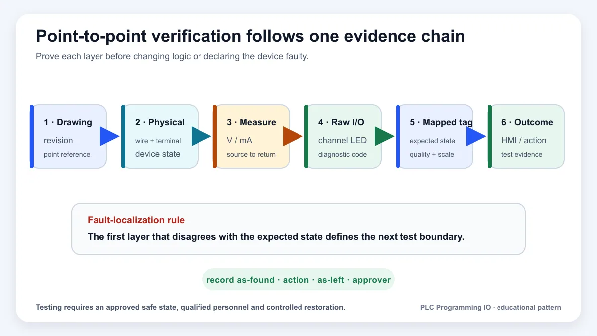
Architecture review checklist
- Every field signal maps to one approved I/O-list row.
- Power blocks distinguish system, field and load power.
- The CPU/firmware and engineering-software versions are explicit.
- Retained data is intentional and has restart behavior.
- Tasks and data producers have one owner.
- Remote values include validity and timeout behavior.
- Output ratings cover steady current and inrush.
- Safety functions reference the approved safety design.
- Downloads, online edits and backups follow revision control.
- FAT/SAT tests trace to each important block and interface.
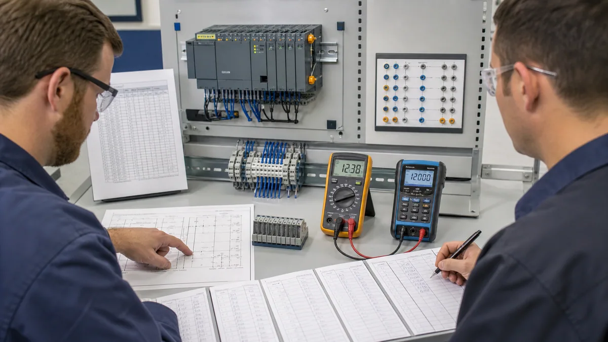
Download the companion PLC block-to-document traceability matrix and PLC architecture acceptance matrix. Together with the planning worksheet, they turn each box and arrow into an owner, source artifact, test and unresolved limitation.
Read the diagram as two interacting paths
The physical path carries energy or a measurable field signal. The information path carries a representation of that condition. They meet at the I/O module but are not interchangeable.
For an input, trace:
process state → field device → cable/terminals → module channel → raw value/status → engineering tag → program consumer
For an output, trace:
program request → arbitration/permissives → output command → module channel → field circuit/final element → feedback → program proof
This explains a common diagnostic mistake. A green output instruction proves that the program requested a Boolean state at that point in execution. It does not prove the output image, module channel, supply, interposing device, coil, motor or process response. Likewise, an HMI value can be plausible while its quality is bad or its timestamp is stale.
Scan-by-scan conveyor trace
Use symbolic states so the trace is portable:
| Scan boundary | Photoeye input image | Start request | Jam input | Program command | Physical output/feedback evidence |
|---|---|---|---|---|---|
| 0 | 0 | 0 | 0 | 0 | starter off; feedback off |
| 1 | 0 | 1 | 0 | 1 | output update pending/issued by platform schedule |
| 2 | 0 | 0 | 0 | 1 | starter/drive feedback expected within declared time |
| 3 | 1 | 0 | 0 | 1 | product detected; command remains owned by sequence |
| 4 | 1 | 0 | 1 | 0 | jam response requests stop; physical release still requires proof |
| 5 | 1 | 0 | 1 | 0 | feedback-off must arrive inside timeout or separate fault is raised |
This table deliberately separates the input image, program state, output request and physical proof. Exact same-scan behavior depends on the platform's task and I/O-update model, instruction order, network schedule and whether immediate/direct I/O access is used. Build the trace from the selected controller manual and measured timestamps.
Data age, not only scan time
For a remote sensor used by a periodic task, a conservative consumer-age budget can include:
sensor update + module conversion/filter + network production/delivery + wait to consuming task + program execution
For a resulting remote output, add command production/delivery, output-module update and actuator response. Jitter and retry/reconnect behavior belong in the worst-case model. The controller's displayed task scan does not include every upstream and downstream delay.
| Diagram arrow | Timing record needed | Validity record needed |
|---|---|---|
| field input to module | sensor and module update/filter | channel diagnostics, range and wire-break behavior |
| module to CPU/tag | local update or network RPI/cycle and transport | connection state, status/quality and last-good time |
| tag to program | task period, phase, priority and preemption | ownership and stale-data policy |
| program to output | producer task and output/network update | arbitration, constraint and command quality |
| output to feedback | electrical/mechanical/process delay | independent confirmation and timeout |
Block-to-document traceability
Every architecture block should point to controlled evidence. If a reviewer cannot move from a box to the exact catalog number, drawing, software object and acceptance case, the diagram is descriptive but not an engineering index.
| Block | Minimum source artifacts | Online/physical evidence | Acceptance question |
|---|---|---|---|
| power | single-line/schematic, load budget, product manual | voltage/current, diagnostics and protection state | does every required power domain remain within limits? |
| CPU | hardware configuration, firmware/software compatibility, task design | online identity, utilization, scan/jitter and faults | is the exact target executing the approved revision predictably? |
| memory | data design, retention/restart specification and backup manifest | capacity, retained values and restore result | do only intended values survive each restart/restore case? |
| inputs | I/O list, channel/module manual, schematic and scaling contract | raw/quality/engineering values at independent references | can every field state be traced without ambiguity? |
| outputs | load schedule, module/load manual, schematic and control narrative | request, limited/applied state and physical feedback | does each command create the intended action and safe loss behavior? |
| communications | topology, interface contract, address/identity register and security design | link/session/cyclic status, data quality, age and events | do loss, reconnect and wrong-device cases behave as declared? |
| engineering | software/version manifest, project archive and access/change policy | project/controller comparison and audit record | can the approved system be recovered without an uncontrolled source? |
Troubleshoot from the first failed boundary
| Symptom | First evidence to compare | Likely boundary | Do not change first |
|---|---|---|---|
| CPU will not power | incoming/controller voltage, polarity, protection and supply diagnostics | power/protection/load | program logic |
| input LED changes but tag does not | exact channel identity, raw data, module/config status and process-image path | I/O configuration/map/update | field sensor adjustment |
| tag changes but rung does not respond | task/routine scheduling, alias/source, instruction order and forces | program execution/ownership | terminal wiring |
| rung true but output tag false | arbitration, interlocks, duplicate writers and output mapping | program ownership/map | replace output module |
| output tag true but channel off | module connection, inhibit/fault, channel config and output image | controller-to-module boundary | change sequence |
| channel on but load off | supply/common, protective device, wiring, interposing element and load | electrical/final element | force another software point |
| remote value freezes | connection quality, sequence/timestamp and last-good age | network/producer/validity | accept retained value as current |
| restart creates wrong state | retention, initialization, mode ownership and physical feedback | memory/startup design | make every value retentive |
Frequently asked questions
What is a PLC diagram?
A PLC diagram is a visual representation of part of a programmable-controller system. The term is ambiguous: it may mean a functional block diagram, wiring schematic, I/O map, network topology, ladder program, panel layout or process drawing. Name the artifact and revision before relying on it. This page focuses on the functional block diagram and how it connects to the other controlled documents.
What are the main blocks in a PLC?
The usual functional blocks are power, CPU/scheduler, memory, input interfaces, output interfaces, communications, engineering access and diagnostics. Compact controllers may combine them physically; distributed architectures may spread them across remote devices and networks. Exact functions, isolation and update behavior come from the selected catalog numbers and manuals.
How does a PLC block diagram work?
Field inputs are conditioned by modules and represented as controller data. Scheduled logic consumes that data, updates internal states and produces commands. Output interfaces convert commands into electrical or network actions. Feedback closes the evidence path. Power, memory, communications and diagnostics support the chain. The drawing describes ownership; it does not promise one universal scan order.
Is a PLC block diagram the same as a wiring diagram?
No. A block diagram shows major functions and information flow. A wiring diagram shows an exact circuit: supplies, conductors, terminals, contacts, commons, protection and references. A block arrow from a sensor to an input module cannot tell you sourcing/sinking polarity, channel common, voltage, isolation or wire numbers.
Is a PLC diagram the same as ladder logic?
No. Ladder logic is a programming-language representation executed by a controller. A PLC functional diagram shows hardware/software boundaries around that program. Ladder can prove the requested logical state at a point in execution; it cannot by itself prove field current, module health, actuator movement or process response.
What is the CPU in a PLC diagram?
It represents the controller resources that schedule tasks/programs, execute instructions, exchange data, manage memory and diagnostics, and respond to faults. Actual platforms expose different schedulers and execution models. Record the exact CPU, firmware, engineering release, task periods/priorities, watchdogs and measured utilization rather than treating “CPU” as a generic box.
What is PLC memory in a block diagram?
It represents multiple storage classes: project/configuration, working data, process images, retained variables, diagnostics and sometimes removable backup media. Retention is not automatically desirable. Define which values survive warm/cold restart, download, power loss and restore, and how stale commands or modes are initialized.
What is the PLC input-process-output cycle?
It is a useful learning model: acquire inputs, execute logic, publish outputs, repeat. Some controllers use process images for selected I/O, while modules, networks, immediate access, periodic/event tasks and higher-priority functions update on other schedules. For an exact point, document its producer, consumer, phase, age and quality.
Why can a PLC output be on in software but the motor remain off?
The online program may show a request before or apart from the physical chain. Check output ownership/interlocks, output tag/map, module connection and channel state, field/load supply, protective devices, interposing relay/contactor/drive, wiring and run feedback. Diagnose the first mismatch. Do not bypass protection or force an output without authorization and a controlled test plan.
What is a PLC I/O map?
It is the contract connecting each physical or network point to module/channel identity, address/tag, signal type/range, engineering meaning, quality, fail behavior and drawing/test references. A strong map also records producer, consumer and owner. It is more specific than a block diagram and less complete than the full circuit/control narrative.
How do remote I/O and networks change the PLC diagram?
They insert device identities, links/switches, protocol roles, cyclic schedules, connection status, data maps, quality/age and reconnect behavior between field signals and controller logic. Show physical topology and application ownership separately. A line labelled with a protocol name does not define the data, timing or safe loss response.
What is a PLC process image?
It is a controller-managed memory representation of selected inputs or outputs used to provide defined access semantics for program execution. Platforms differ: points may use separate partitions, asynchronous module data or immediate/direct access. Use the exact controller manual and project configuration to determine when a given value is copied and consumed.
How do I draw a PLC block diagram?
Set the system boundary, place field inputs and outputs, then add power domains, exact controller/I/O roles, memory/retention, tasks, networks, HMI/SCADA and engineering access. Label producers, consumers, command/feedback direction, quality/timeouts and document references. Keep functional boxes distinct from buildable wiring. Peer-review it against the BOM, I/O list, schematics, topology and control narrative.
Can a PLC block diagram prove a safety function?
No. It can show an interface to an independently engineered safety system, but an ordinary high-level box does not establish risk reduction, architecture category, diagnostic coverage, response time, component suitability or validation. Use the applicable safety lifecycle, approved safety design and exact safety product instructions.
Primary sources and review scope
Reviewed 31 August 2026. Use the revision applicable to the exact product and installation; vendor families do not share one universal architecture or update model.
- IEC 61131-1:2003 general information for programmable controllers — IEC
- IEC 61131-2:2017 equipment requirements and tests — IEC
- IEC 61131-3:2025 programming languages — IEC
- S7-1200 system manual and process-image behavior — Siemens
- S7-1200 product/manual index — Siemens
- Logix Designer project components — Rockwell Automation
- Logix Designer tasks — Rockwell Automation
- Logix 5000 Tasks, Programs and Routines manual, September 2025 — Rockwell Automation
- Rockwell Automation programmable-controller literature library
- Task configuration and I/O update settings — CODESYS
- PLC task system — Beckhoff Automation
- Modicon controller product documentation — Schneider Electric
- EtherNet/IP technology and CIP roles — ODVA
- PROFINET technology description — PROFIBUS & PROFINET International
- Modbus protocol specifications — Modbus Organization
- OPC UA specifications — OPC Foundation
- NIST SP 800-82 Rev. 3, OT security — NIST
- Control of hazardous energy, 29 CFR 1910.147 — OSHA
The figures are original conceptual/editorial illustrations. They are not vendor schematics, approved electrical drawings, network designs, P&IDs or safety architectures. Qualified personnel must use exact hardware manuals, local electrical rules, hazard controls and controlled engineering procedures.
Continue from architecture to implementation
Now run it · free · no signup
Run your first PLC program in your browser
Build one rung, press Run and watch the output change in a free browser lab. Nothing to install and no signup needed to try it.
Ownership disclosure: PLC Programming IO and PLC Simulation Software are operated by the same publisher.


