ControlLogix Programming Guide: 5580 Chassis & Tasks
Design and program a ControlLogix 5580 system around chassis ownership, I/O, EtherNet/IP, tasks, equipment modules, produced tags, testing and commissioning.
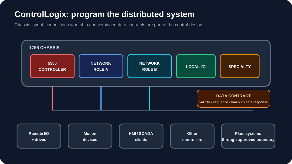
ControlLogix 5580 is Rockwell Automation's modular Logix controller family for applications that justify a 1756 chassis architecture, high controller capacity, extensive communications, process or motion performance, or plant-level integration. Program quality still depends on fundamentals: define ownership, isolate I/O, structure tasks, give each equipment module one state owner, and test communication and restart behaviour.
Download the Logix controller architecture worksheet (CSV)
When ControlLogix is the right owner
| Requirement | Why ControlLogix may fit |
|---|---|
| Modular chassis architecture | Broad 1756 module and communication ecosystem |
| High-performance motion | 5580 family supports demanding integrated-motion applications |
| Large plant area or line | More capacity for equipment, data and connections |
| Multiple industrial networks | Chassis communication modules can separate network roles |
| Process control | Logix process instructions and plant integration |
| Redundancy requirement | Specific ControlLogix architectures support redundancy; design it as a system |
| Integrated safety | GuardLogix options are available for qualified safety designs |
Rockwell states that ControlLogix 5580 supports high-performance process and motion applications, faster execution and higher information exchange between control and supervisory layers. The official 5580 product page links the current 1756-SG002 selection guide and 1756-TD001 controller specifications.
ControlLogix vs CompactLogix
Both use the Logix programming model and Studio 5000. The decision is architectural.
| Area | CompactLogix 5380 | ControlLogix 5580 |
|---|---|---|
| Physical platform | Compact controller with 5069 local I/O | Modular 1756 chassis |
| Typical scope | Machine, skid, cell, smaller process area | Large machine, line, process area or plant system |
| Communications | Integrated ports plus supported modules/devices | Chassis communication-module flexibility |
| Expansion | Compact local/remote architecture | Chassis and remote I/O architecture |
| Redundancy | Check exact platform capability | Supported in defined ControlLogix architectures |
| Project method | Logix tasks/programs/routines | Same model, often larger distributed scope |
Do not decide from this table alone. Compare exact controller memory, nodes, axes, safety, redundancy, environment and lifecycle requirements in the current selection guides.
1. Design the chassis before the program
Create a slot schedule:
| Slot | Catalog number | Role | Network/owner | Spare strategy |
|---|---|---|---|---|
| 0 | Exact controller | Primary application owner | Controller project | N/A |
| 1 | Communication module if required | Plant or device network | Defined subnet | Documented |
| 2…n | I/O or specialty modules | Local signals/functions | Controller ownership | Named spares |
Check chassis and power-supply loading with Rockwell's current documentation. Decide whether network separation, time synchronisation, motion, redundancy or safety imposes particular slot/module rules.
“Leave three empty slots” is not a complete spare strategy. Record whether the power, connection capacity, cabinet space, heat and software design can actually support the anticipated expansion.
Live mini-lab
Try it: press START, then STOP
A stop-dominant seal-in rung: START latches the motor output through its own contact, and STOP breaks the circuit.
Watch the output lamp: it stays on after START until you press STOP.
Free to start · runs in your browserOpens plcsimulationsoftware.com — same team
2. Define ownership and data flow
For every module and important tag, answer:
- Which controller owns the I/O connection?
- Which controller produces the data?
- Which controllers consume it?
- What happens if the producer is unavailable?
- Is the data a command, status, setpoint or diagnostic?
- What update rate is required?
- Which side validates range, freshness and mode?
Avoid casual cross-controller reads and writes. Define a data contract:
Line1_To_Utilities
  Heartbeat
  DataValid
  SequenceNumber
  ProductionState
  AirDemand
  WaterDemand

Utilities_To_Line1
  Heartbeat
  DataValid
  AirAvailable
  WaterAvailable
  ShutdownRequest
A heartbeat by itself proves only that one value changes. Pair it with data-valid logic, timeout handling and a defined safe response.
3. Structure tasks and programs
A large project becomes maintainable when execution structure follows plant structure.
Continuous_Task
 ├─ IO_Mapping
 ├─ Area_Utilities
 ├─ Area_Conveying
 ├─ Area_Packaging
 └─ Alarm_and_HMI

Periodic_100ms
 ├─ Process_Control
 └─ Data_Quality

Periodic_1s
 ├─ Runtime_Accumulation
 └─ Supervisory_Exchange
This is illustrative. Measure execution time, choose priorities deliberately and keep the watchdog appropriate. Do not move ordinary code into a faster periodic task without understanding controller loading and data consistency.
4. Build equipment modules with one state owner
For a pump, valve, conveyor or drive, one routine/AOI should own the equipment state. Other programs request operation; they do not write the output directly.
Recommended interface:
Cmd: start, stop, reset, mode requests;Perm: start permissives;Intlk: run interlocks or trips;Cfg: timeouts and selectable behaviour;Sts: state and feedback;Alm: actionable abnormal conditions;Out: final non-safety command.
This pattern makes it possible to simulate an equipment module without physical I/O and to trace why an output is off.
5. Map I/O once
Module-defined tags should enter a mapping layer. The application uses stable symbolic tags. Benefits:
- module replacement or migration affects one routine;
- input quality/status can be handled consistently;
- analog scaling is visible;
- simulation overrides are controlled;
- HMI tags are insulated from raw module structure;
- drawings and I/O lists reconcile cleanly.
For output modules, define what happens on controller fault, communication loss, inhibit and program mode. The PLC program cannot correct an output behaviour that was never specified in the module/device configuration.
6. Produced/consumed tag design
Use produced/consumed tags for structured cyclic data exchange where supported and justified.
Good practices:
- Group related values in a user-defined type.
- Include schema/version or sequence information for critical interfaces.
- Keep commands separate from status.
- Make command handshakes explicit.
- Define stale-data timeout and response.
- Avoid changing a live UDT casually; consumers depend on its layout.
- Include interface tests in FAT/SAT.
For occasional, non-cyclic transfers, a message instruction may be more appropriate. Select based on behaviour and load rather than habit.
7. First system test: remote I/O and another controller
Test matrix:
| Test | Expected result |
|---|---|
| Remote I/O adapter power loss | Module fault visible; affected equipment moves to defined state |
| One network cable removed | Behaviour matches approved topology/redundancy design |
| Produced data freezes | Consumer timeout asserts; stale commands are rejected |
| Controller changes to Program mode | Output behaviour matches configuration and hazard analysis |
| Controller restarts | sequence state and commands recover intentionally |
| HMI repeats a write | command handshake prevents duplicate action |
| Module inhibited for maintenance | inhibit is visible, controlled and removed before handover |
8. Commissioning workflow
Controller and chassis
- verify chassis, power supply, controller and module catalog numbers;
- compare slot schedule with the I/O tree;
- check firmware and Studio 5000 compatibility;
- verify keying and ownership settings;
- inspect major/minor faults and controller status.
Networks
- verify every interface and subnet;
- check duplicate addresses and device identities;
- baseline switch and module diagnostics;
- prove data-loss and recovery behaviour;
- verify time synchronisation where timestamps or motion require it.
Application
- validate physical I/O one point at a time;
- prove permissives before commands;
- test trips without bypassing the safety design;
- test restart, mode transfer and communication loss;
- remove forces, temporary messages and commissioning bypasses;
- archive the final ACD file and change record.
Failure patterns
| Pattern | Consequence | Better design |
|---|---|---|
| Multiple routines write one output | Last-rung-wins behaviour | One equipment owner |
| HMI writes internal state directly | Uncontrolled transitions | Request/acknowledge commands |
| Raw module tags throughout logic | Expensive migrations | I/O mapping layer |
| No stale-data handling | Old data treated as current | Validity, sequence and timeout |
| Periodic tasks added without load review | Watchdog/priority problems | Measured execution budget |
| Module inhibit used as normal control | Hidden unavailable I/O | Controlled maintenance state |
| Undocumented controller-to-controller tags | Fragile integration | Versioned interface contract |
Primary references
- Rockwell Automation, ControlLogix 5580 controllers.
- Rockwell publications linked there: 1756-SG002 system selection guide, 1756-TD001 controller specifications and 1756-TD006 chassis specifications.
- Rockwell Automation, Product Compatibility and Download Center, for current firmware and Studio 5000 compatibility.
Related guides
Now run it · free to start
Practise Allen-Bradley-style logic in your browser
Work XIC, XIO, OTE, TON and CTU logic without a Studio 5000 licence. An independent learning tool — free to start, no install.
Ownership disclosure: PLC Programming IO and PLC Simulation Software are operated by the same publisher.


