Motor Start/Stop Ladder Logic: Seal-In & Interlocks
Build and test motor start/stop ladder logic with a seal-in contact, stop-dominant behavior, overload feedback, restart tests and simulator practice.
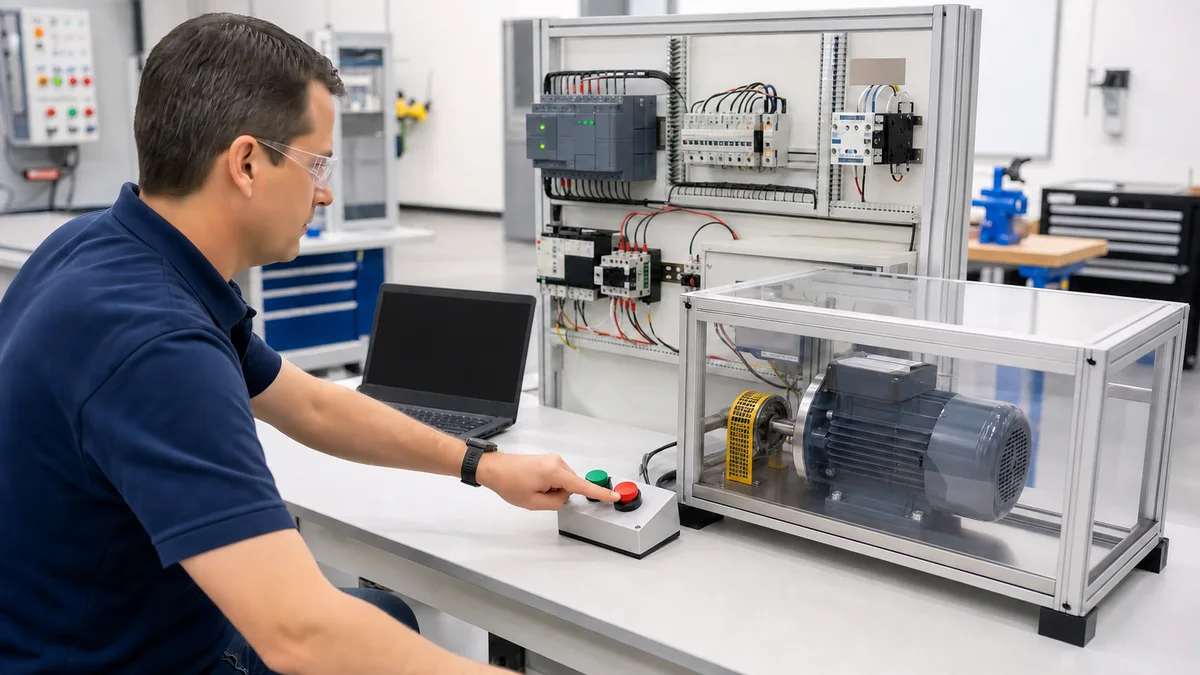
Motor start/stop ladder logic should be stop-dominant: a momentary start request sets a run request, but a false stop-chain status, overload/fault status, mode change or restart-required state removes it. Use descriptive positive-state input names such as StopCircuitHealthy so the physical normally-closed wiring is not confused with the ladder instruction.
The rung below controls an ordinary process run request. It does not design the motor power circuit, overload protection, emergency-stop function, guarding or hazardous-energy isolation. Translate the pseudocode for the exact PLC, starter/drive and machine risk assessment.
Stop-dominant acceptance matrix
| Test | Inputs/action | Expected run request |
|---|---|---|
| Idle | Healthy chain, start released | Off |
| Start | Healthy chain, press and release Start | Latches on |
| Normal stop | Run on, open StopCircuitHealthy |
Off immediately in the next evaluated logic cycle |
| Simultaneous | Start true while stop chain is false | Off; stop wins |
| Overload/fault | Open MotorProtectionHealthy while running |
Off and fault status recorded |
| Reset only | Restore health and press Reset without Start | Off |
| Held start | Hold Start while restoring the stop chain | Off until a new start edge if the design requires anti-restart |
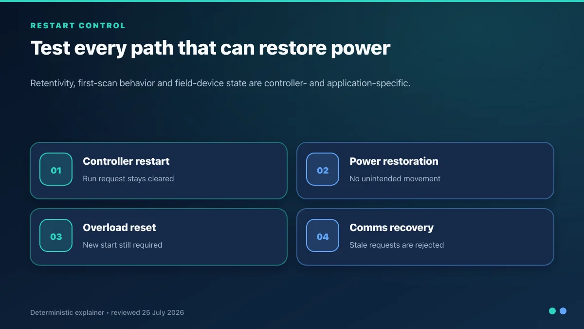
| Controller restart | Cycle RUN/STOP or power in a controlled test | Off until the approved reset/start sequence |
Run the motor start/stop acceptance matrix in the browser, then repeat it on the target controller with outputs safely isolated.
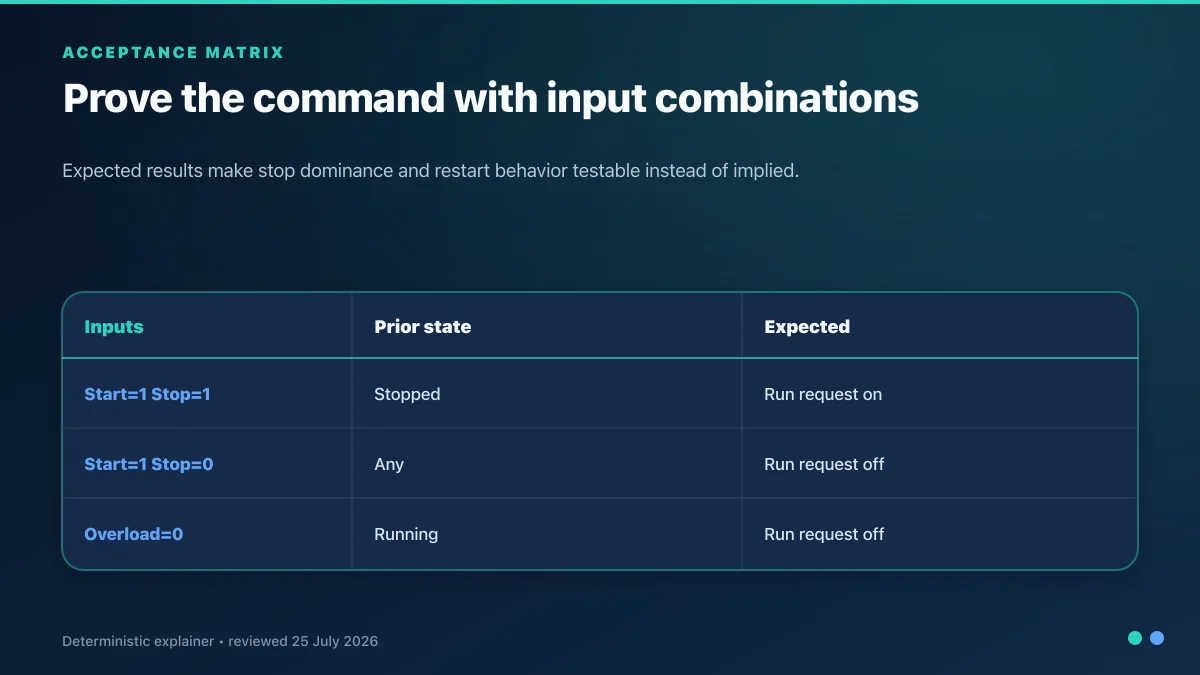
Table of Contents
- The Three-Wire Control Principle
- Seal-In Contacts in Ladder Logic
- Adding the E-Stop
- Thermal Overload Interlock
- Jog vs Run Mode
- Forward / Reverse Motor Control
- Common Mistakes That Kill the Circuit
- Dialect Differences: AB vs Siemens vs IEC
- Putting It Into Production
The Three-Wire Control Principle
Before any ladder, understand what you're copying. The classic hardwired motor starter circuit uses three wires between the pushbuttons and the motor contactor coil:
- A momentary normally-open (N.O.) Start button — closes briefly when pressed.
- A momentary normally-closed (N.C.) Stop button — opens briefly when pressed.
- An auxiliary contact on the motor contactor itself — closed whenever the motor is running.
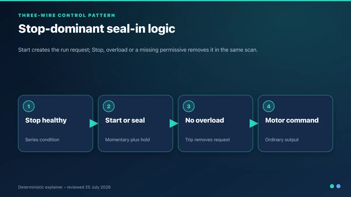
The Start button is in parallel with the contactor's own auxiliary contact. The Stop button is in series with both of them. Press Start, current flows, contactor energises, the aux contact closes and keeps the coil energised even when you release Start. Press Stop, series chain breaks, coil de-energises, motor stops. The aux contact across the Start button is the "seal-in" — it seals the start signal so you don't have to hold your finger on the button.
Three properties matter:
- De-energise-to-stop intent. In the classic hardwired circuit, loss of control voltage or an open series stop contact removes the contactor command. A PLC input/output path introduces additional failure modes that must be assessed.
- Normally closed stop wiring. A healthy circuit is energised and an open circuit removes the run permissive. Name the PLC bit for its state—
StopCircuitHealthy—rather than for the pushbutton hardware. - Stop dominance. If Start and Stop are asserted together, the stop condition must win. Test this explicitly rather than relying on rung appearance.
Ladder logic can reproduce the normal operating sequence, but it does not inherit the hardwired circuit's safety properties automatically.
Seal-In Contacts in Ladder Logic
Here is the minimal PLC version of the three-wire circuit:
|  Start      StopCircuitHealthy       MotorRunRequest |
|---| |-----------| |---+------------(      )---------|
|                  |                |
|  MotorRunRequest |                |
|---| |------------+                |
Reading the rung:
Startis a momentary N.O. input. When the operator pushes the start button, this bit goes true for as long as the button is held.StopCircuitHealthycomes from a physically normally-closed control circuit in this example, so the PLC bit is TRUE at rest and is evaluated with examine-on (| |). Verify the real input polarity and fault behavior.MotorRunRequeston the branch is the command memory used for the seal. It is not proof that the contactor, starter or motor is running; use separate auxiliary/drive feedback for that.
Press Start with the stop circuit healthy and the run request latches. Opening the stop circuit clears the request. Add a separate anti-restart state if a held Start input must not restart the machine when the stop circuit becomes healthy again.
Adding the E-Stop
The normal-control rung can consume a status from the safety system so the run request clears when an emergency-stop function is active:
| Start  SafetyHealthy  StopCircuitHealthy      MotorRunRequest |
|--| |-------| |---------------| |---------+--------( )--------|
|                                            |                   |
| MotorRunRequest                            |                   |
|--| |---------------------------------------+                   |
This status contact is not the safety function. The actual emergency-stop chain may use a safety relay, safety PLC, fail-safe I/O and/or a safety-integrated drive. Its architecture, stop function, performance level/SIL, reset and diagnostic coverage come from the risk assessment and validated component design.
The standard PLC may display state, inhibit the ordinary command and require a new start edge after the safety system is reset. It must not silently substitute for the certified logic or allow an HMI override of the emergency-stop function.
Stop categories are described in IEC 60204-1; ISO 13850 covers emergency-stop design principles, and ISO 13849-1 is used in performance-level design. A Category 2 stop is not an emergency-stop option under ISO 13850. Read the E-stop safety circuit guide before adapting this status pattern.
Thermal Overload Interlock
Motor protection may be provided by an overload relay, electronic motor-protection device, starter or drive. Use its documented healthy/trip feedback as a permissive to the normal run request:
| Start  SafetyHealthy  ProtectionHealthy  StopCircuitHealthy  RunReq |
|--| |-------| |--------------| |----------------| |-------+----( )--|
|                                                         |           |
| RunReq                                                  |           |
|--| |----------------------------------------------------+           |
ProtectionHealthy is true only when the selected protection device permits operation. Manual versus automatic reset, trip class and restart rules are device- and risk-assessment-specific. Configure and test them; do not assume every overload requires a physical reset.
Most plants add a "Motor Faulted" latch bit in code too, so the HMI can display the fault clearly and the alarm log captures the event:
|  OL                        Motor_Faulted |
|---|/|----------------------(  Latch  )   |
|                                           |
|  Reset_PB    Motor_Faulted    Motor_Faulted |
|---| |---------| |------------(  Unlatch )   |
The diagnostic latch can preserve the event after the protection device returns healthy. Whether acknowledgement is required before another start is a documented operating requirement; the alarm latch itself must not reset or bypass the protection device.
Jog vs Run Mode
Many machines need a "jog" mode — press-and-hold to move the motor, release to stop. The jog rung doesn't seal:
| Jog_PB  SafetyHealthy  ProtectionHealthy  StopCircuitHealthy  RunReq |
|---| |---------| |-------------| |---------------| |---------(  )----|
Note the absence of the parallel Motor feedback contact. As soon as the operator releases the Jog button, the rung goes false and the motor stops.
The tricky part: a real machine has both jog and run. The standard pattern uses a Mode_Run / Mode_Jog selector bit to route between the two:
| Mode_Run  Start  SafetyHealthy  ProtectionHealthy  StopCircuitHealthy |
|---| |-----| |--------| |-------------| |----------------| |----+----|
|                                             |            |
|           RunReq                            |            |
|           ---| |----------------------------+            |
|                                                          |
| Mode_Jog  Jog_PB  SafetyHealthy  ProtectionHealthy  StopCircuitHealthy |
|---| |-----| |---------| |-------------| |----------------| |---------|
|                                                          |
|                                                          (common RunReq coil)
Two parallel branches, both feeding the same Motor coil. Run mode seals, jog mode doesn't. Mode selector decides which branch is active. Only one mode bit can be true at a time — enforced either by a keyed HMI or an interlock in code.
Forward / Reverse Motor Control
A reversing-starter circuit uses separate forward and reverse commands and must prevent conflicting contactors. The electrical design, contactor ratings, mechanical/electrical interlock and reversal timing must follow the exact starter manufacturer's instructions.
| Start_FWD  SafetyHealthy  ProtectionHealthy  StopCircuitHealthy  REV |
|---| |----------| |-------------| |----------------| |----------|/|--+--(FWD) |
|                                               |                  |
|          FWD_Out                              |                  |
|          ---| |-------------------------------+                  |
|                                                                  |
| Start_REV  SafetyHealthy  ProtectionHealthy  StopCircuitHealthy  FWD |
|---| |----------| |-------------| |----------------| |----------|/|--+--(REV) |
|                                               |                  |
|          REV_Out                              |                  |
|          ---| |-------------------------------+                  |
The Reverse_Out N.C. contact in the FWD branch and the FWD_Out N.C. contact in the REV branch form the software interlock. One direction's coil is fed through the other direction's N.C. feedback, so the second coil can't energise until the first has fully de-energised.
Use the starter manufacturer's approved electrical and mechanical interlocking arrangement in addition to command interlocks in software. Verify that neither command can energise during overlap, welded/stuck feedback, controller startup or a rapid direction change. Use the forward/reverse scenario to practice the state logic, not to validate the power circuit.
Common mistakes to catch in review
- Ambiguous input names.
Stopdoes not reveal whether TRUE means pressed or healthy. UseStopCircuitHealthy, document the physical contact and verify a disconnected wire. - Wrong ladder polarity. If the healthy input is TRUE, use an examine-on condition. Test the physical button, removed terminal and failed input channel.
- Treating status as safety logic. A safety-system status may clear the ordinary run request, but the certified safety function remains separate and validated.
- Held-start restart. A maintained or stuck start input can restart a simple seal-in rung when the stop chain recovers. Require a new rising edge where the risk assessment or operating specification demands it.
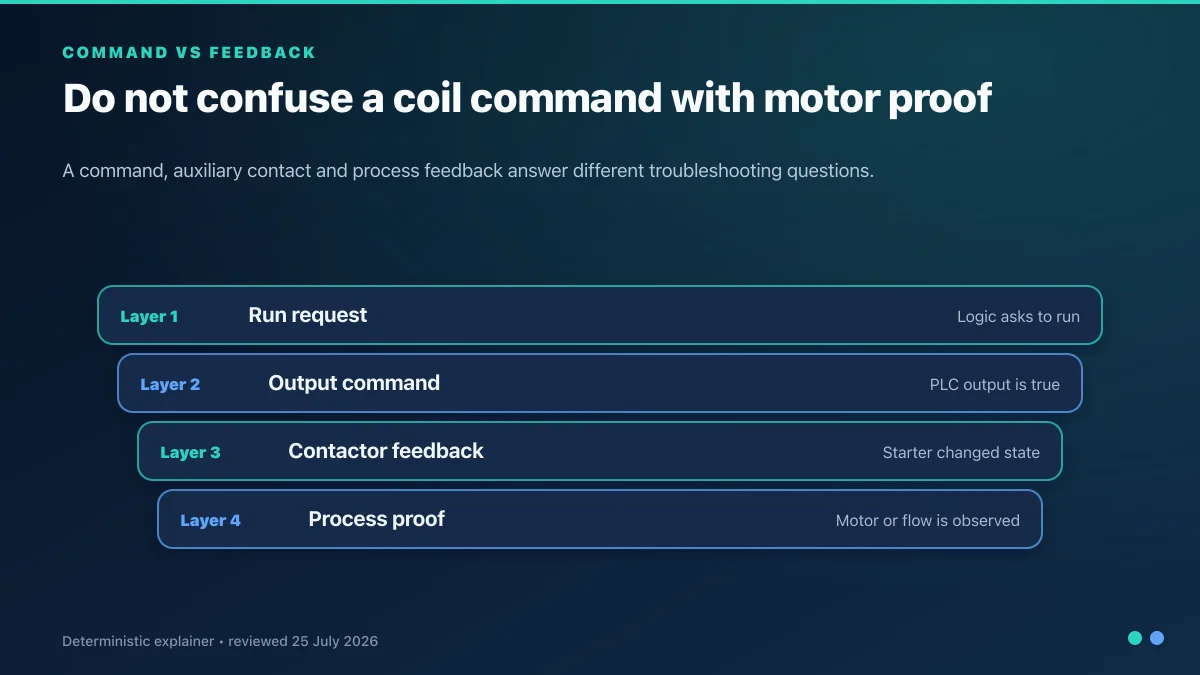
- Confusing command and feedback. Keep
MotorRunRequest, output command, starter/drive ready and actual running feedback as separate signals. Add start and stop feedback timeouts. - Undefined protection reset. Document whether the protection device is manual or automatic reset and whether an operator acknowledgement plus new start is required.
- Jog that seals. Jog/inch logic should match the risk-assessed mode and enabling-device requirements; a copied run seal can create unintended continued motion.
- Incomplete reversing interlock. Follow the starter manufacturer's approved electrical/mechanical arrangement and test conflicting commands plus stuck feedback.
- Retained run state. Do not allow retained command memory to cause an unintended restart after CPU STOP/RUN, power restoration or communications recovery.
- Untested fault state. Read and test controller, output module, drive and network behavior for CPU STOP, comms loss and device faults with the motor safely isolated.
Dialect Differences
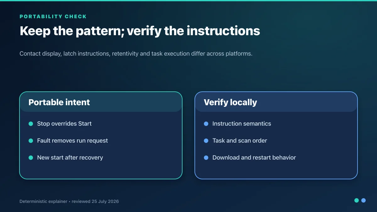
The state requirements can be equivalent across platforms, but instruction execution, task behavior, output update and tag retention differ. Re-run the acceptance matrix after every translation.
Allen-Bradley (Studio 5000, tag-based):
XIC Start_PB XIC SafetyHealthy XIC ProtectionHealthy XIC StopCircuitHealthy OTE MotorRunRequest
XIC MotorRunRequest   (parallel with Start_PB for the command seal)
Use an input-conditioning routine so the rung consumes positive-state names. Add a first-scan/restart inhibit and separate physical feedback.
Siemens (TIA Portal, #Tag notation):
A "Start_PB"
A "SafetyHealthy"
A "ProtectionHealthy"
A "StopCircuitHealthy"
= "MotorRunRequest"
In LAD, implement the same stop-dominant state requirement. If Set/Reset storage is used, ensure every stop and fault condition reaches the reset path and test simultaneous set/reset behavior.
IEC 61131-3 / Codesys: IEC 61131-3 defines languages and common concepts, not a single universal address map or runtime. Use symbolic variables and the selected CODESYS target's I/O mapping and task configuration.
The scenario we've built on plcsimulationsoftware.com runs your code in whichever dialect you choose — toggle between IEC, AB, and Siemens from a single dropdown on the same scenario.
Putting It Into Production
A motor start/stop circuit that's headed to production adds a few more things:
- HMI feedback. A "Motor Running" light driven directly by a real motor-feedback aux contact, not by the coil bit.
- Run-hours counter. Accumulate verified running feedback, define retention and rollover, and compare it with the maintenance system during commissioning.
- Start-frequency limit. Enforce the motor/starter/drive manufacturer's permitted starts and restart interval for the actual load and ambient conditions; do not copy a generic count or delay.
- Alarm logging. Every E-stop, every overload, every fault transition written to a data buffer with timestamp for later analysis. Our batch-mixer scenario shows the alarm-buffer pattern end-to-end.
- Drive or soft-starter integration. Map commands, ready/running/fault feedback, communications-loss behavior and safe-torque-off status according to the exact device manual.
Key Takeaways
- Three-wire control is a useful sequence model, but PLC logic does not automatically inherit the failure behavior of a hardwired circuit.
- Positive-state names (
StopCircuitHealthy,ProtectionHealthy) make physical input polarity easier to review. - A standard PLC may consume safety status; the safety-rated function is engineered and validated separately.
- Command, physical output and actual running feedback are different states and should have explicit timeouts.
- A stop-dominant test matrix catches simultaneous inputs, held Start, recovery and controller-restart defects before commissioning.
Related Reading
- Complete ladder logic tutorial
- Ladder logic symbols complete guide
- PLC programming best practices
- Siemens PLC programming tutorial
- RSLogix 5000 programming guide
Once the concept clicks, build the circuit and watch it run. The scan cycle, the seal-in behaviour, and the fault-recovery patterns are all much clearer when the motor is actually turning.


