Mitsubishi FX5U Programming Guide: Wiring & First Project
Configure an FX5U in GX Works3, identify the exact I/O variant, map devices and labels, build a first motor project, simulate, download and commission it safely.
The Mitsubishi FX5U is a MELSEC iQ-F compact PLC programmed in GX Works3. A dependable first project starts by decoding the complete CPU model, because supply and output variants affect wiring. Configure the exact hardware, create descriptive global labels, isolate physical devices in mapping logic, simulate the sequence, then download and prove each field point under a controlled commissioning plan.
Download the FX5U project checklist (CSV)
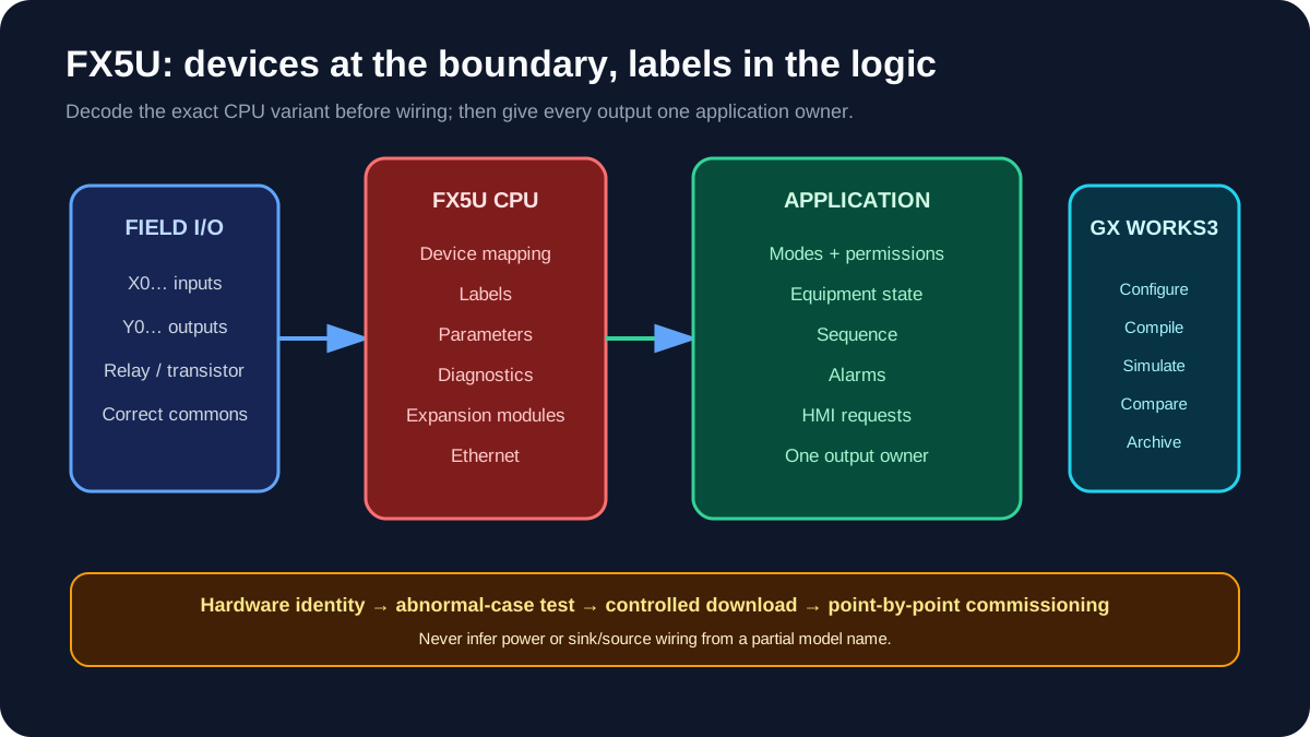
FX5U quick-start sequence
| Step | Deliverable | Stop condition |
|---|---|---|
| Identify | Full CPU and module model codes | Label or manual does not match the design |
| Wire | Power, commons, inputs and outputs | Supply/output type is uncertain |
| Configure | Exact GX Works3 series, CPU and modules | Hardware configuration does not compile |
| Map | X/Y devices to named labels | I/O list and drawing disagree |
| Program | Modes, permissives, sequence and alarms | Output has more than one owner |
| Test | Simulation and abnormal-case record | Restart/fault behaviour is undefined |
| Commission | I/O check, functional test and archive | Force/bypass remains active |
1. Decode the complete model before wiring
FX5U models combine point count, output construction and power/sink-source variants in the order code. For example, MR and MT distinguish relay and transistor output families, but that is not enough to wire the PLC. The suffix and regional model matter.
Use the exact nameplate and current Mitsubishi manual to verify:
- AC or DC supply;
- relay or transistor outputs;
- sink/source arrangement;
- input common wiring;
- terminal assignment;
- allowable load current and protection;
- compatible expansion modules and adapters.
Mitsubishi's current MELSEC iQ-F manual index lists the FX5S/FX5UJ/FX5U/FX5UC hardware manual, application manual, communication manual and instruction/function-block reference. At the time of this review, the hardware manual entry was revised in April 2026. Recheck before a real design.
2. Relay vs transistor output
| Output family | Practical strength | Design checks |
|---|---|---|
| Relay | Can switch supported AC or DC loads and provides contact isolation by group/design | Contact rating, life, inrush, switching frequency, suppression |
| Transistor | Faster solid-state switching for supported DC loads | Sink/source variant, polarity, leakage, load voltage/current, protection |
A relay output is not automatically suitable for a large contactor coil, and a transistor output is not automatically suitable for a pulse train. Check the exact channel and load specifications. Use interposing relays or approved interface modules where the field load, isolation or maintenance standard requires them.
3. Build the GX Works3 project
- Create a new project and select the MELSEC iQ-F series.
- Select the exact FX5U CPU.
- Add expansion modules/adapters in their physical order.
- Set Ethernet parameters from the approved network schedule.
- Configure required intelligent-function modules.
- compile the parameters before application logic;
- save a clean baseline.
For an existing controller, read and archive the current project and parameters before making a change. Compare the uploaded project, CPU firmware and documentation rather than assuming the latest offline file is running.
Live mini-lab
Try it: press START, then STOP
A stop-dominant seal-in rung: START latches the motor output through its own contact, and STOP breaks the circuit.
Watch the output lamp: it stays on after START until you press STOP.
Free to start · runs in your browserOpens plcsimulationsoftware.com — same team
4. Use devices and labels intentionally
Mitsubishi device names such as X, Y, M, D and T are compact and familiar:
| Device | Common role | Example |
|---|---|---|
X |
Physical input | X0 start pushbutton |
Y |
Physical output | Y0 motor-contactor command |
M |
Internal bit | mode, state or intermediate condition |
D |
Data register | setpoint, scaled value or count |
T |
Timer device | start-feedback or dwell timer |
Labels add intent:
X0  →  PB_Start
X1  →  StopCircuitHealthy
X2  →  MotorOverloadHealthy
X3  →  MotorRunFeedback
Y0  ←  MotorRunCommand
Do not let the HMI, sequence and alarms each write Y0. Create one final command owner and let other program sections make requests.
5. First project: motor with feedback
Requirements:
- Manual start is allowed only when stop circuit and overload are healthy.
- Stop removes the run command.
- Feedback must arrive within three seconds.
- A failed start latches an alarm.
- Reset is accepted only when the initiating condition is healthy.
Illustrative logic:
Ready := StopCircuitHealthy AND MotorOverloadHealthy;

IF ResetPB AND Ready THEN
    StartFail := FALSE;
END_IF;

IF StopPB OR NOT Ready OR StartFail THEN
    MotorRunCommand := FALSE;
ELSIF StartPB THEN
    MotorRunCommand := TRUE;
END_IF;

StartFeedbackTimer(IN := MotorRunCommand AND NOT MotorRunFeedback, PT := T#3s);

IF StartFeedbackTimer.Q THEN
    StartFail := TRUE;
END_IF;
Run Structured Text in the simulator
Emergency stopping and other safety functions must not be implemented by this ordinary example. Use a risk-assessed safety circuit or safety controller designed and validated to the applicable requirements.
6. Add operating modes and sequence ownership
Use explicit modes:
- Off: no normal run command.
- Manual: an authorised operator requests one device at a time, with required interlocks still active.
- Auto: the sequence requests equipment through the same equipment interface.
- Maintenance/test: only if formally specified, access-controlled and risk-assessed.
Mode selection should not bypass overload, process trip or safety behaviour. Manual means “manual request,” not “unprotected output.”
For a conveyor, define states such as Stopped, Starting, Running, Stopping and Faulted. State logic is clearer than a collection of unrelated SET/RST coils.
7. Simulate and test
GX Works3 simulation can verify much of the application logic. Build test cases first:
- Normal start and stop.
- Start with overload unhealthy.
- Feedback fails to arrive.
- Feedback disappears while running.
- Reset requested while fault remains.
- Manual-to-Auto transfer.
- CPU restart with each important state.
- Analog value below, inside and above configured range if analog I/O is used.
Capture the input state, expected transition, observed state and result. Test the failure path as carefully as the happy path.
8. Connect and download
- Verify the engineering PC network adapter.
- Search for the controller using the approved connection method.
- Identify the CPU from its network and hardware details.
- Compare/read the controller before overwriting an existing machine.
- Confirm outputs and machinery are in an approved safe condition.
- Write parameters and program under the site's procedure.
- Check diagnostics before enabling normal operation.
After commissioning, clear device tests, forced values and temporary bypasses. Save the final GX Works3 project with the controller, firmware and date in the archive record.
FX5U troubleshooting map
| Symptom | First checks |
|---|---|
| CPU cannot be found | PC adapter, IP subnet, direct/through connection, cable |
| Input LED changes but program tag does not | X address, mapping, input common and project monitor target |
| Y device is on but load is off | output variant, load supply/common, fuse, interposing device |
| Hardware parameter error | exact module, order, adapter position and supported configuration |
| Unexpected retained state | latch/retain settings, initialisation and restart test |
| Ethernet device intermittent | addressing, duplicate IP, switch/cabling and protocol parameters |
| High-speed signal missed | correct input/function assignment, wiring and documented frequency limit |
Quality gate
- Full CPU and module codes match the hardware manual.
- Supply, input common and output construction are verified.
- Network settings follow a controlled schedule.
- Physical devices are mapped to readable labels.
- Each output has one program owner.
- Modes do not bypass interlocks or safety.
- Test cases include faults and restart behaviour.
- Commissioning evidence and final project are archived.
Primary references
- Mitsubishi Electric, MELSEC iQ-F manuals and current revisions.
- Mitsubishi Electric, FX5S/FX5UJ/FX5U/FX5UC hardware manual. Verify the latest revision in the manual index before use.
Related guides
Now run it · free to start
Practise Mitsubishi-style PLC logic in your browser
Work X/Y/M/D devices, latches, timers and counters without GX Works. An independent learning tool — free to start.
Ownership disclosure: PLC Programming IO and PLC Simulation Software are operated by the same publisher.


