PLC Analog Input Scaling and Calibration: Formula, Code and Field Proof
Scale PLC analog inputs from raw counts to engineering units, verify the result with a five-point loop check, and separate software scaling from instrument calibration.
PLC analog input scaling in one answer
PLC analog input scaling maps the number delivered by an input channel onto the instrument's engineering range. For two known endpoints, use:
Scaled = ScaledLow
       + (Raw - RawLow) × (ScaledHigh - ScaledLow)
       / (RawHigh - RawLow)
For an S7-1200 channel configured so that 4–20 mA is represented by raw 0–27,648, and a pressure transmitter ranged −10 to 90 bar, raw 13,824 is halfway through both spans:
Pressure = -10 + (13,824 - 0) × (90 - (-10)) / (27,648 - 0)
         = -10 + 0.5 × 100
         = 40 bar
That mathematical result is necessary, but it is not proof that the installed loop measures correctly. A complete job also confirms the exact module, channel range and data format; preserves under-range and over-range evidence; checks numeric types; compares several injected or applied reference points; records as-found and as-left results; and verifies what the HMI, alarm and control logic actually consume.
Critical distinction: scaling is a software/data transformation. Calibration compares an indication with a reference under stated conditions and may lead to an authorized adjustment. Changing PLC endpoints until one field reading “looks right” can hide a transmitter, wiring, module, range or reference problem.
Use the free analog scaling calculator to check the arithmetic in either direction. Then use this guide's five-point loop-check worksheet to prove the implemented channel rather than trusting a single midpoint.
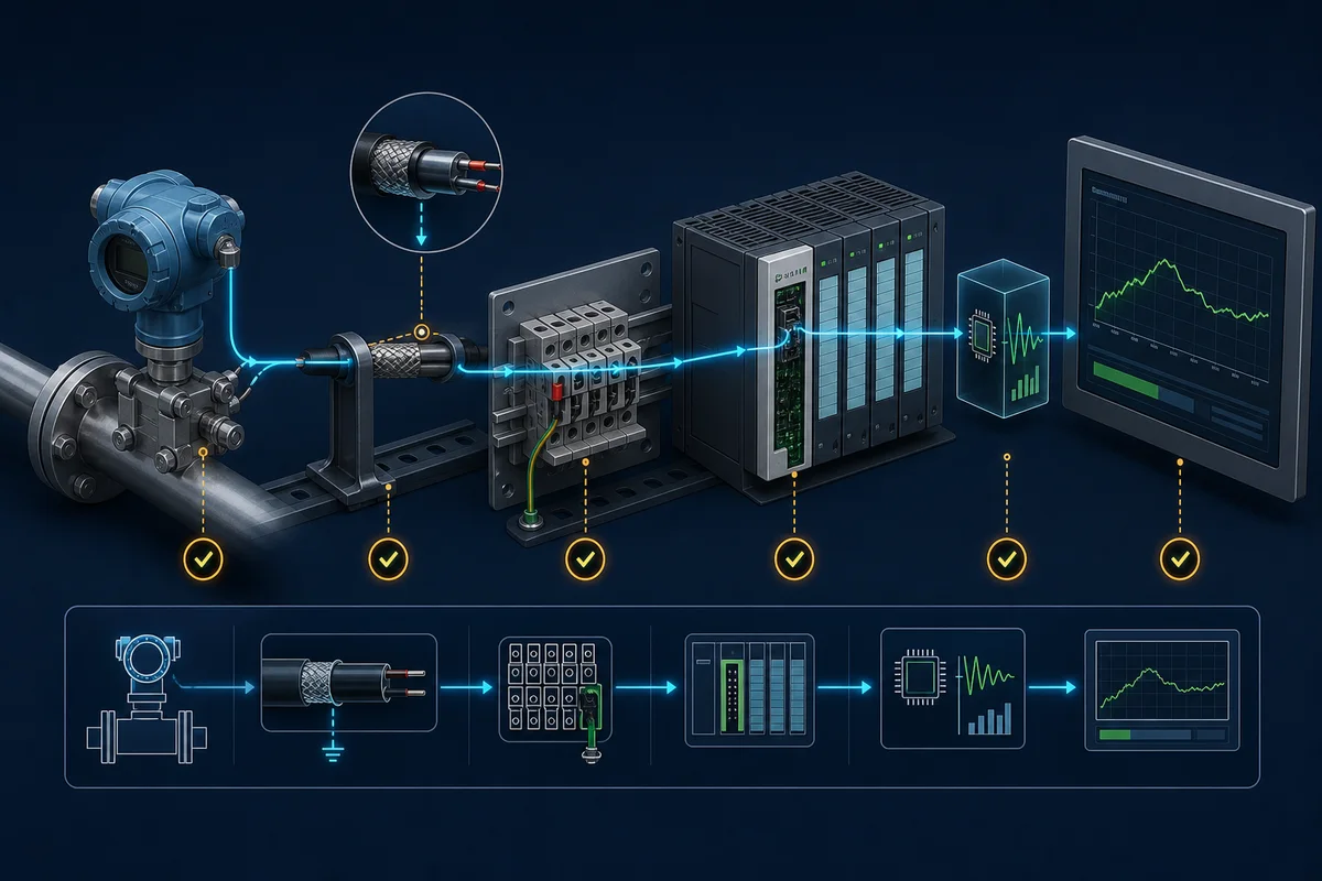
What this page owns
This is the scaling-and-calibration implementation owner. Adjacent pages retain their narrower jobs:
| Need | Use this specialist | Ownership boundary |
|---|---|---|
| current-loop wiring and electrical behavior | 4–20 mA current-loop guide | loop power, burden, polarity and live-zero fundamentals |
| analog signal/module selection | PLC analog I/O signals | current versus voltage, resolution, isolation and module fit |
| failed installed channel | PLC I/O troubleshooting | first-disagreement diagnosis across field and controller |
| transmitter adjustment procedure | transmitter loop calibration | instrument-specific reference, adjustment and certificate workflow |
| reusable arithmetic | PLC math instructions | numeric operations beyond analog channels |
| quick independent calculation | analog scaling calculator | endpoint conversion, not physical calibration or target validation |
Define the six endpoints before writing code
“A 4–20 mA input is 0–32,767” is not an engineering specification. The current range, module representation and transmitter range are three different contracts. Document all six endpoints and their units.
| Layer | Low endpoint | High endpoint | Example | Source of truth |
|---|---|---|---|---|
| physical measurand | PVLow |
PVHigh |
−10 to 90 bar | approved instrument data sheet / P&ID / range record |
| loop signal | SignalLow |
SignalHigh |
4 to 20 mA | transmitter configuration and receiver range |
| controller representation | RawLow |
RawHigh |
0 to 27,648 | exact module, channel setting and selected data format |
Also record the tag type, input update rate/filter, module diagnostics, PLC task period, HMI unit/precision and downstream consumers. The same part number may support raw/proportional counts, engineering units, percent or PID-oriented formats. A copied raw endpoint can therefore be wrong even when the hardware family is correct.
Siemens' S7-1200 system manual, for example, documents raw 0 at 4 mA and 27,648 at 20 mA for the 4–20 mA current range. The same table documents different electrical meanings for a 0–20 mA range. Rockwell's 1769 documentation exposes selectable Raw/Proportional, Engineering Units, Scaled-for-PID and Percent Range formats. Treat format as part of the interface—not a cosmetic display choice.
Endpoint manifest
| Field | Example value | Why it matters |
|---|---|---|
| loop ID / channel | PT-204 / Local AI 3 |
connects code to drawing and field label |
| transmitter range | −10…90 bar | defines the physical span and units |
| signal range | 4…20 mA | defines electrical endpoints and live-zero behavior |
| module and revision | SM 1231, exact order number |
resolves input type, resolution and diagnostics |
| channel configuration | current, 4…20 mA | distinguishes it from 0…20 mA or voltage |
| data representation | raw integer | decides what the PLC tag means |
| raw nominal endpoints | 0…27,648 | formula inputs for this exact configuration |
| diagnostic endpoints | module-specific | keeps faults separate from valid process values |
| PLC source tag/type | %IW... : INT |
prevents address and conversion mistakes |
| scaled tag/type | PT204_PV : REAL |
preserves fractional engineering values |
| update/task period | recorded values | supports filter and stale-data reasoning |
| range authority | approved instrument record | prevents casual HMI re-ranging from changing control |
Download the analog-channel contract (CSV) and fill it before copying any instruction block.
Derive the two-point formula instead of memorizing it
Two points define a straight line. Let x be the input/raw value and y the engineering value:
y = m × x + b
m = (ScaledHigh - ScaledLow) / (RawHigh - RawLow)
b = ScaledLow - m × RawLow
The endpoint form used at the top of this guide is algebraically identical, but it is easier to review because all four configuration constants remain visible.
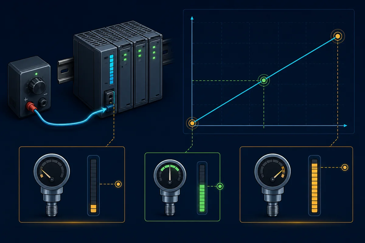
Worked example: 4–20 mA, −10 to 90 bar
Assumptions are explicit:
- the installed transmitter is approved and configured for −10 to 90 bar;
- the exact S7-1200 input channel is configured for 4–20 mA;
- its representation table maps nominal 4 mA to raw 0 and 20 mA to raw 27,648;
- the source tag is read as an integer, then converted to floating point before division; and
- out-of-range quality is evaluated separately from the calculated value.
| Test point | Applied current | Expected raw | Span fraction | Expected pressure |
|---|---|---|---|---|
| 0% | 4.000 mA | 0 | 0.00 | −10.00 bar |
| 25% | 8.000 mA | 6,912 | 0.25 | 15.00 bar |
| 50% | 12.000 mA | 13,824 | 0.50 | 40.00 bar |
| 75% | 16.000 mA | 20,736 | 0.75 | 65.00 bar |
| 100% | 20.000 mA | 27,648 | 1.00 | 90.00 bar |
At the 75% point:
Pressure = -10 + (20,736 - 0) × 100 / 27,648
         = -10 + 75
         = 65 bar
The negative lower range makes a common bug visible: scaling only by span (raw × 100 / 27,648) gives 75, not 65, because it omits the −10 bar offset.
Reverse and non-zero ranges
The same formula supports 100 to 0%, 20 to 4 mA, −50 to 50 °C or any other linear endpoint pair. Do not force ScaledHigh > ScaledLow; reverse-acting ranges can be intentional. Do reject a zero raw span, because division by zero means the configuration contract is invalid.
| Range shape | Valid? | Review point |
|---|---|---|
| raw 0…27,648 → 0…100% | yes | ordinary rising scale |
| raw 0…27,648 → −10…90 bar | yes | non-zero engineering offset |
| raw 0…27,648 → 100…0% | potentially | confirm reverse action is intentional |
| raw 1,000…1,000 → 0…100% | no | zero denominator; flag configuration fault |
| raw −27,648…27,648 → −10…10 V | yes | bipolar range and signed type required |
A reusable Structured Text scaling block
The following IEC-style function separates calculated value, limited value and quality. Adapt types, conversion functions and diagnostic inputs to the exact target; it is a behavioral reference, not a drop-in certified library.
FUNCTION_BLOCK FB_AnalogScale
VAR_INPUT
    RawValue       : DINT;
    RawLow         : DINT;
    RawHigh        : DINT;
    EULow          : LREAL;
    EUHigh         : LREAL;
    UnderLimitRaw  : DINT;
    OverLimitRaw   : DINT;
    ModuleFault    : BOOL;
    ClampOutput    : BOOL;
END_VAR
VAR_OUTPUT
    ValueEU        : LREAL;  // extrapolated diagnostic value
    LimitedEU      : LREAL;  // optional bounded consumer value
    Good           : BOOL;
    UnderRange     : BOOL;
    OverRange      : BOOL;
    ConfigFault    : BOOL;
END_VAR
VAR
    Fraction       : LREAL;
    LowBound       : LREAL;
    HighBound      : LREAL;
END_VAR

ConfigFault := RawHigh = RawLow;
UnderRange  := RawValue < UnderLimitRaw;
OverRange   := RawValue > OverLimitRaw;
Good        := NOT (ConfigFault OR ModuleFault OR UnderRange OR OverRange);

IF NOT ConfigFault THEN
    Fraction := DINT_TO_LREAL(RawValue - RawLow)
                / DINT_TO_LREAL(RawHigh - RawLow);
    ValueEU := EULow + Fraction * (EUHigh - EULow);

    LowBound := MIN(EULow, EUHigh);
    HighBound := MAX(EULow, EUHigh);
    IF ClampOutput THEN
        LimitedEU := LIMIT(LowBound, ValueEU, HighBound);
    ELSE
        LimitedEU := ValueEU;
    END_IF;
ELSE
    ValueEU := EULow;
    LimitedEU := EULow;
END_IF;
END_FUNCTION_BLOCK
Download the IEC-style scaling oracle (ST). Compile or translate it on the selected target, because IEC 61131-3 establishes language concepts while conversions, overloads, MIN/MAX/LIMIT availability and diagnostic interfaces remain implementation-specific.
Numeric implementation failures
| Failure | Symptom | Mechanism | Prevention |
|---|---|---|---|
| integer division before conversion | output remains near low end, then jumps | fractional result is truncated | convert numerator/denominator to REAL/LREAL before division |
| intermediate integer overflow | wrong sign or implausible value | multiplication exceeds source type | convert before subtract/multiply; inspect target overflow behavior |
| wrong signedness | high input appears negative | 16-bit word interpreted incorrectly | match module-defined type and representation |
| stale raw tag | smooth but delayed/frozen PV | mapping or update path is wrong | capture module tag, copied tag and timestamp/change counter |
| rounding each stage | systematic steps | repeated conversion loses resolution | keep full precision; round only at presentation boundary |
| hidden clamping | flat value at limits | evidence is discarded before diagnosis | retain extrapolated value and quality separately |
| duplicate scaling | correct at one point, wrong elsewhere | module already provides engineering units | record data format and scale exactly once |
| copied constants | fixed span/offset bias | endpoints belong to another module/range | bind constants to channel contract and review version |
Vendor implementation boundaries
Siemens S7-1200 / S7-1500
The S7-1200 manual defines NORM_X as (VALUE - MIN) / (MAX - MIN) and SCALE_X as VALUE × (MAX - MIN) + MIN. It also documents extrapolation behavior outside the nominal range. A typical flow is:
Normalized := NORM_X(MIN := RawLow, VALUE := RawInput, MAX := RawHigh)
Pressure   := SCALE_X(MIN := -10.0, VALUE := Normalized, MAX := 90.0)
Select the block types deliberately. Preserve the input module's diagnostics and 7FFF/overflow behavior instead of treating every integer as a valid process sample. The exact representation depends on module/order number and selected range.
Rockwell SLC / MicroLogix and Logix families
Rockwell's SLC 500 reference documents SCP (Scale with Parameters) for SLC 5/03, 5/04 and 5/05, while legacy manuals also document SCL. That does not make SCP a universal built-in Studio 5000 Logix instruction. For a Logix controller, use the exact controller/instruction set, module-supplied engineering format, reviewed math or a governed Add-On Instruction as appropriate.
Rockwell 1769 analog modules can expose several data formats, and their under-range/over-range channel bits are valuable evidence. Resolve the actual tag definition and channel configuration before deciding whether software scaling is required.
CODESYS, Schneider, Beckhoff and other IEC targets
Use the same endpoint contract, but confirm each target's conversion, overflow, LIMIT, function-block call and retained-value semantics. Do not label generic ST “vendor neutral” and assume it compiled unchanged. Record the compiler, runtime, library and task used to verify the translated block.
| Platform decision | Evidence to capture |
|---|---|
| native normalize/scale instructions | exact help/manual version and parameter types |
| module engineering-units format | channel configuration and actual tag meaning |
| reusable custom function block | source version, call order, instance ownership and tests |
| Add-On Instruction / library block | revision, signature, change approval and deployed target |
| manual ladder arithmetic | execution order, intermediate types, overflow and divide-by-zero behavior |
Scaling is not calibration
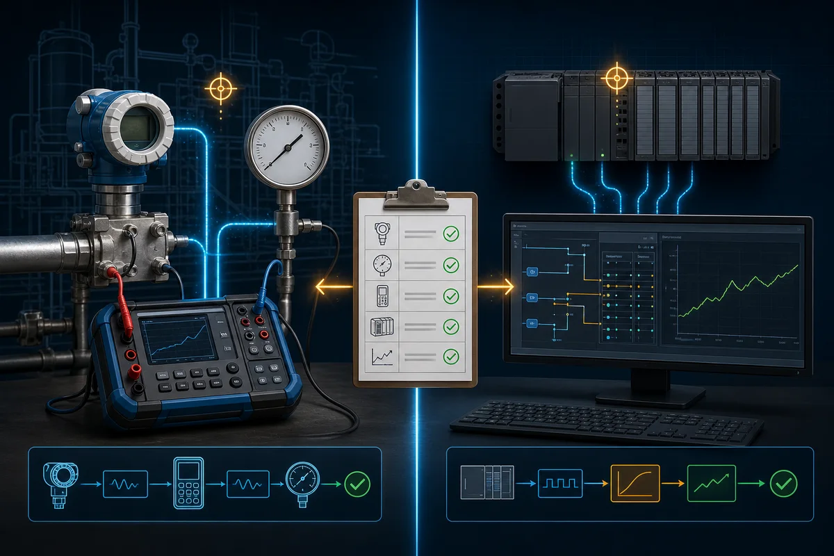
NIST distinguishes calibration, adjustment and verification and emphasizes that traceability belongs to a measurement result supported by a documented chain and uncertainty—not merely to an instrument with a sticker. In plant work, terminology and required records depend on the quality system, procedure, regulator and instrument.
| Activity | Question answered | May change something? | Minimum evidence |
|---|---|---|---|
| scaling configuration | what EU corresponds to this controller value? | yes, program/configuration | approved endpoints, version, code review and tests |
| verification / loop check | does the observed chain meet stated acceptance criteria? | normally no | applied reference, conditions, readings, tolerance and result |
| calibration | what is the relation between reference values and indication, with associated uncertainty? | not necessarily | method, reference, results, uncertainty/traceability as required |
| adjustment | should the instrument be altered to reduce indication error? | yes | authorization, as-found data, adjustment and as-left data |
| trim/compensation in PLC | should software correct a characterized bias? | yes, high governance | approved rationale, bounds, ownership, audit trail and revalidation |
Never make an undocumented PLC offset the default response to a bad loop check. First locate the disagreement: process reference, sensor, transmitter, current path, input module, raw representation, scaling, HMI formatting or downstream use.
Five-point field verification
Only trained and authorized people should connect test equipment, open panels, disturb process instruments or work near hazardous energy. Follow site isolation, electrical, process and calibration procedures. A browser exercise cannot authorize or validate field work.
Before applying a reference
- identify the loop, process consequence and responsible owner;
- confirm permits, isolation/override and alarm/interlock handling;
- record module, channel, signal range, data format and current code version;
- identify whether the test injects current at the PLC, at marshaling, or through the transmitter;
- record reference instrument ID, range, calibration status and relevant uncertainty;
- capture as-found raw, scaled, HMI and quality values; and
- define point-by-point tolerance and restoration criteria before testing.
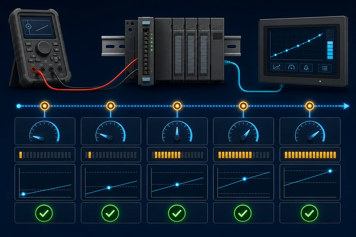
Example evidence table
The table uses the worked −10…90 bar S7-1200 contract. Acceptance values below are examples only; use the project's approved tolerance and reference uncertainty.
| Direction | Applied mA | Expected raw | Observed raw | Expected bar | Observed bar | Error bar | Quality | Result |
|---|---|---|---|---|---|---|---|---|
| up | 4.000 | 0 | 3 | −10.00 | −9.99 | +0.01 | good | evaluate to project tolerance |
| up | 8.000 | 6,912 | 6,905 | 15.00 | 14.97 | −0.03 | good | evaluate |
| up | 12.000 | 13,824 | 13,816 | 40.00 | 39.97 | −0.03 | good | evaluate |
| up | 16.000 | 20,736 | 20,742 | 65.00 | 65.02 | +0.02 | good | evaluate |
| up | 20.000 | 27,648 | 27,640 | 90.00 | 89.97 | −0.03 | good | evaluate |
| down | 12.000 | 13,824 | record | 40.00 | record | calculate | record | evaluate hysteresis |
At minimum, repeat the low and high endpoints after any adjustment, then restore the process path and prove alarm/interlock/quality behavior under the approved procedure. Do not leave a forced value, bypass, calibrator connection or disabled alarm behind.
Diagnose by injecting at successive boundaries
| Injection or observation point | If correct here | If wrong here | Next boundary |
|---|---|---|---|
| physical reference at sensor | process/reference is plausible | reference, impulse line or sensing point suspect | transmitter indication/output |
| transmitter output terminals | transmitter conversion is plausible | transmitter range, trim, power or sensor path suspect | field/marshalling terminals |
| PLC-side loop current | cable/current path is plausible | wiring, barrier, isolator, burden or grounding suspect | module channel raw tag |
| module raw tag | input conversion/configuration is plausible | wrong channel/range/format, module or termination suspect | scaled program tag |
| scaled tag | formula/constants/type are plausible | software mapping/scaling defect | HMI/historian/controller consumer |
| HMI/controller value | end-to-end data path is plausible | alias, unit, rounding, stale data or duplicate scaling suspect | output/control response under procedure |
This first-disagreement method prevents random endpoint edits. For example, if 12.000 mA is correct at the PLC terminals but the raw tag is at 75%, inspect channel range/data format before touching the transmitter. If the raw tag is correct and the engineering value is biased by exactly 10 bar across all points, inspect EULow rather than wiring.
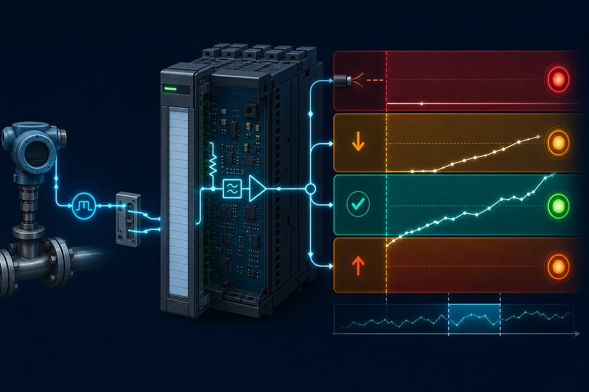
Preserve diagnostic zones before clamping
A 4–20 mA live zero creates room below 4 mA for under-range and failure signaling, but exact thresholds and meanings are device- and module-specific. Endress+Hauser documentation for one device using NAMUR NE 43, for example, distinguishes under-range at or below 3.8 mA and failure at or below 3.6 mA, with corresponding high-side ranges. That is evidence for that documented behavior—not permission to hard-code the same thresholds for every loop.
| Value to expose | Purpose | Example consumers |
|---|---|---|
RawValue |
exact module evidence | commissioning and diagnosis |
ValueEU |
extrapolated engineering value | trend, diagnostics and fault context |
LimitedEU |
bounded value if a consumer requires it | explicitly designed calculation/control path |
Good / quality enum |
whether value is usable for its purpose | interlocks, alarming, display decoration |
UnderRange / OverRange |
directional electrical/process evidence | maintenance alarm and fault history |
ModuleFault |
hardware/channel diagnostic | first-out and device-health logic |
LastGoodEU plus age |
continuity aid, never disguised as live | display/history under an explicit stale policy |
Do not overwrite ValueEU with zero on every fault and call that safe. Zero may command heat, speed, flow or makeup behavior through downstream logic. Define a per-consumer response: inhibit control, hold last good for a bounded time, transfer to manual, use a validated fallback, trip ordinary control, or request an independently engineered protection action.
Filtering without hiding the fault
A first-order filter can reduce display jitter, but it must use an intentional time constant and task interval:
alpha = dt / (tau + dt)
Filtered = Filtered + alpha × (ValueEU - Filtered)
For a 100 ms task and 2.0 s time constant, alpha = 0.1 / 2.1 ≈ 0.04762. Reusing that coefficient in a 20 ms task changes the real filter. Initialize the state deliberately at startup, call it at a known cadence, and decide what happens on bad quality. Filtering before fault detection can delay or conceal a broken-loop transition.
| Design question | Required answer |
|---|---|
| where is filtering applied? | module, transmitter, PLC, HMI or several layers |
| what is the effective update interval? | measured/configured input plus task behavior |
| what dynamics must remain visible? | process event, control response and fault transition |
| how is startup initialized? | first good sample, configured default or retained state |
| what happens on bad quality? | freeze, invalidate, reinitialize or controlled fallback |
| who may change the time constant? | governed role, bounds and audit record |
Build a measurement error budget
Scaling arithmetic can be essentially exact while the measurement result remains uncertain. Potential contributors include reference uncertainty, sensor/transmitter performance, ambient effects, installation, loop isolators, input-module accuracy, quantization, noise, sampling, wiring, linearization and repeatability.
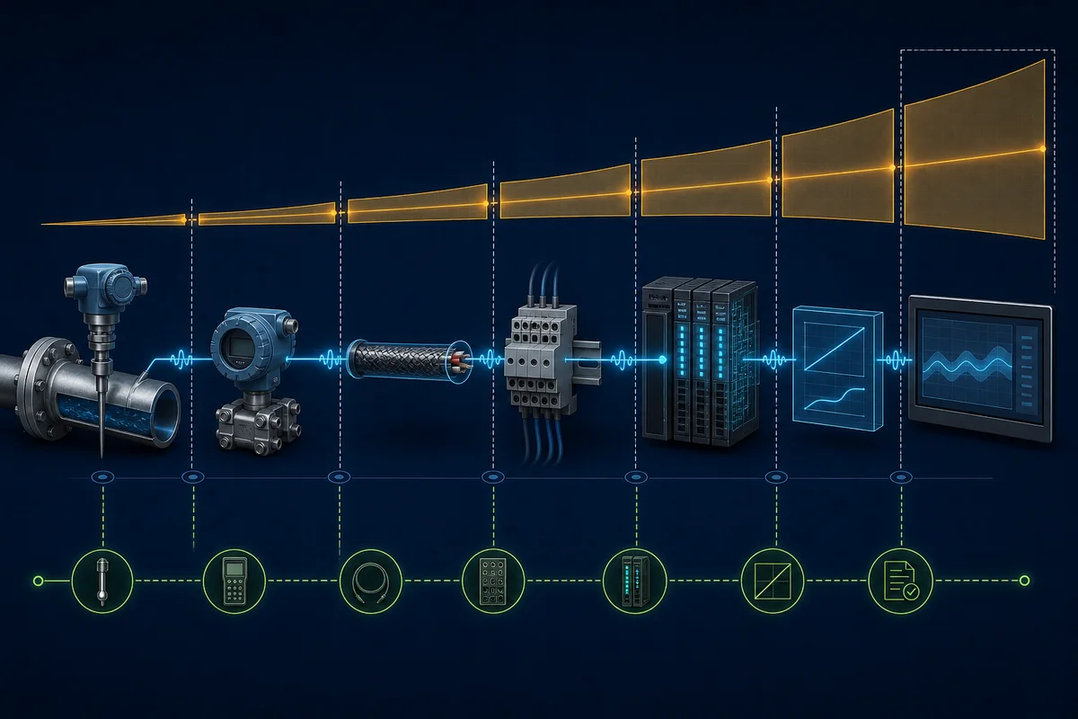
For screening only, suppose approved specifications and conditions support independent standard-uncertainty contributions equivalent to 0.10%, 0.15% and 0.05% of span. A root-sum-square screening estimate is:
sqrt(0.10² + 0.15² + 0.05²) = 0.187% of span
A worst-case arithmetic sum would be 0.30% of span. Neither result is automatically the reportable uncertainty: specifications may use different confidence, distributions, reference conditions, denominators and correlations. Convert each contribution consistently and follow the approved uncertainty method. The example only shows why “the transmitter is ±0.1%, therefore the loop is ±0.1%” is incomplete.
Resolution is not accuracy
For raw 0–27,648 mapped across a 100 bar span, one count represents approximately:
100 bar / 27,648 counts = 0.003617 bar/count
That is the scaling increment, not the full installed accuracy. A display with three decimals can show quantization, noise and bias more precisely without measuring the process more accurately.
Acceptance matrix
| Case | Stimulus | Expected result | Failure exposed |
|---|---|---|---|
| 1 | valid low endpoint | exact/within-tolerance low EU, good quality | offset or wrong raw low |
| 2 | valid high endpoint | exact/within-tolerance high EU | span or wrong raw high |
| 3 | midpoint | correct linear midpoint | slope/offset arithmetic |
| 4 | 25% and 75% | correct intermediate values | nonlinearity or duplicate scaling |
| 5 | raw just below nominal | extrapolated evidence plus configured quality | premature clamp |
| 6 | module wire-break diagnostic | bad quality and approved consumer response | diagnostic ignored |
| 7 | raw above nominal | over-range retained and alarmed as designed | hidden over-range |
| 8 | RawHigh = RawLow |
configuration fault; no divide | divide-by-zero |
| 9 | reversed EU range | intentional reverse mapping passes | invalid monotonic assumption |
| 10 | PLC restart at good input | defined initialization and correct value | stale/retentive filter state |
| 11 | quality bad then good | defined recovery and filter reinitialization | stale-value bump |
| 12 | input updates slower than task | age/stale behavior is correct | repeated sample mistaken for fresh data |
| 13 | range changed under authorization | versioned constants and consumers revalidated | undocumented re-range |
| 14 | HMI and historian comparison | same unit/source/quality policy | alias or duplicate conversion |
| 15 | alarm setpoint around boundary | correct engineering unit and hysteresis | setpoint left in old range |
| 16 | force/simulation removed | live source restored and documented | test state left active |
Twelve recurring symptoms and first checks
| Symptom | Likely boundary | First evidence to compare |
|---|---|---|
| correct at 4 mA, wrong at 20 mA | span/raw high | configured format, raw high and transmitter upper range |
| same bias at every point | offset/raw low | lower endpoint and EULow |
| reads 20% at live zero | 0–20 versus 4–20 mismatch | channel range and raw representation |
| reads five times too large/small | engineering span or duplicate conversion | constants and upstream formatted value |
| negative above midpoint | signed type/word interpretation | module-defined tag type and raw hex/decimal |
| flat at zero | fault substitution, wrong address or no loop power | raw tag, module status and loop current |
| flat at upper limit | clamp or overflow sentinel | pre-clamp value and module diagnostics |
| correct PLC, wrong HMI | display/alias/unit | actual HMI source tag and conversion |
| value drifts only after warm-up | sensor/module/environment | field reference and component temperatures |
| noisy raw but smooth HMI | hidden filter | module, PLC and HMI filter settings |
| slow control response | stacked filters/update rates | timestamped raw/scaled/control trend |
| calibration passes at PLC injection but fails through transmitter | upstream physical chain | transmitter, reference, impulse/sensor path and wiring |
Downloadable implementation pack
- Analog-channel endpoint and ownership contract (CSV)
- Five-point as-found/as-left loop-check worksheet (CSV)
- IEC-style scaling and quality oracle (ST)
The files are templates, not a substitute for the approved device manual, calibration method, change process or safety procedure.
Frequently asked questions
What is the PLC analog input scaling formula?
Use ScaledLow + (Raw - RawLow) × (ScaledHigh - ScaledLow) / (RawHigh - RawLow). Convert to an appropriate floating-point type before division and reject a zero raw span. Keep the four endpoints named and traceable to the exact module configuration and instrument range.
How do I scale 4–20 mA to engineering units?
First determine what raw values the exact configured channel returns at 4 and 20 mA. Then map those raw endpoints to the transmitter's lower and upper engineering values with the two-point formula. Do not assume every 4–20 mA module uses the same counts.
Why does an S7-1200 4–20 mA input start at raw zero?
The S7-1200 representation table documents raw 0 as 4 mA and raw 27,648 as 20 mA when the supported channel is configured for the 4–20 mA range. A 0–20 mA configuration has different electrical meaning. Verify the exact module/order number, firmware and selected range.
Is 5,530 always the Siemens raw value for 4 mA?
No. That value is associated with representing 4 mA as 20% of a 0–20 mA 0–27,648 span in some contexts. Siemens modules that support a configured 4–20 mA range can represent 4 mA as raw zero. Use the representation table for the exact module and range, not a remembered Siemens-wide number.
Does Studio 5000 have a universal SCP instruction?
No. Rockwell documents SCP for SLC 500 families, while Logix implementations depend on the target, module data format, available instructions, reviewed arithmetic or a governed Add-On Instruction. Do not paste an SLC instruction example into a Logix design without checking the target instruction set.
Should I clamp an analog input to its engineering range?
Only when a specific consumer requires a bounded value. Preserve the raw value, extrapolated engineering value and quality flags for diagnosis. If you clamp the only value at the nominal limits, you can hide under-range, over-range and failed-signal evidence.
Is PLC scaling the same as transmitter calibration?
No. Scaling maps defined endpoints in software. Calibration establishes a relation between a reference and indication under stated conditions, with the records/uncertainty required by the applicable system. Adjustment changes the instrument. A scaling edit should not conceal a failed calibration.
How many calibration points should I check?
Use the approved procedure and device requirements. A five-point up-scale check at 0, 25, 50, 75 and 100%, plus selected down-scale points, is a useful engineering verification pattern because it tests endpoints, midpoint, slope and possible hysteresis. It is not a universal regulatory requirement.
Why is my scaled value exactly right at one point but wrong elsewhere?
One matching point cannot prove both slope and offset. Compare low and high endpoints first, then intermediate points. Wrong span, duplicate scaling, incorrect data format and nonlinearity can all cross the expected line at one point.
Should a wire break force the process value to zero?
Not automatically. Zero may be a meaningful process value that drives unsafe or damaging downstream behavior. Mark quality bad and apply an approved response separately for each consumer: inhibit, bounded hold, fallback, transfer or ordinary trip as designed.
How do I choose an analog filter coefficient?
Choose a time constant from process and diagnostic needs, then derive the coefficient from the actual update interval, for example alpha = dt / (tau + dt). Document startup and bad-quality behavior. A coefficient copied between task periods produces a different filter.
Does more ADC resolution mean better accuracy?
No. Resolution describes available increments; accuracy and uncertainty also include reference, sensor, transmitter, module, environmental, installation, noise and repeatability effects. More digits can display a wrong result more precisely.
Can I calibrate a loop with a PLC simulator?
No. Simulation can verify formula, types, states, fault policy and acceptance cases. It cannot source traceable current, characterize an instrument, reproduce module electronics or validate the installed measurement chain.
What must I record after changing an analog range?
Record the approved range authority, instrument and module configuration, endpoint constants, code/configuration version, as-found/as-left evidence, alarm/interlock/setpoint review, HMI/historian units, restoration checks and approver. A range change affects every downstream consumer.
Primary and official sources
- Siemens S7-1200 System Manual V4.5 — analog representation and NORM_X/SCALE_X
- Siemens S7-1200 SM 1231 AI 4x13-bit product data
- Rockwell Compact I/O Analog Modules User Manual, 1769-UM002
- Rockwell Compact I/O Isolated Analog Modules User Manual, 1769-UM014
- Rockwell 1769-IF4 module-defined data and channel diagnostics
- Rockwell SLC 500 Instruction Set Reference — SCP
- Rockwell SLC 500 Analog I/O Modules User Manual
- Rockwell MicroLogix 1200/1500 Instruction Set Reference
- Schneider Electric Analog Input Module scaling reference
- CODESYS conversion operators
- CODESYS
LIMIToperator - Endress+Hauser device manual documenting NAMUR NE 43 ranges
- NIST metrological traceability policy and FAQ
- NIST: Traceability Considerations for Characterization and Use of Measuring Systems
- NIST Engineering Statistics Handbook — calibration
- NIST Engineering Statistics Handbook — uncertainty approach
- IEC 61131-3:2025 overview
- NI raw-data scaling and calibration note
Limitations: formulas, examples, code and worksheets are educational engineering references. They do not establish target compilation, device accuracy, calibration traceability, permissible error, process isolation, electrical authorization, hazardous-area suitability, functional safety or regulatory compliance. Use the exact project, hardware and instrument documents; approved procedures; competent personnel; and controlled field evidence.
Next: verify the endpoints in the analog scaling calculator, study the wider analog I/O signal chain, or practise the scaling and quality logic in the interactive PLC simulator. The simulator is operated by the same team; it does not emulate your target compiler, module electronics, transmitter, reference standard, installed process or safety system.


