Loop Check Procedure: Instrument & PLC Commissioning Guide
Commission analog and digital loops from field device to PLC, HMI, alarm and final element. Includes a five-point procedure, worked 4–20 mA example and free loop sheet.
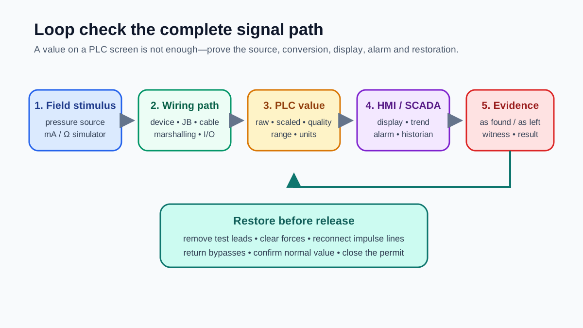
A loop check proves that a field input or output travels through the correct wiring, I/O channel, PLC logic, HMI/SCADA display, alarm or final element—and that the recorded values and actions match the approved design. It is an end-to-end commissioning test, not merely a continuity check or a value forced inside the PLC.
For an analog input, test multiple points across the range and a defined fault condition. For a digital loop, prove both states, normal sense and diagnostic behavior. For an output, control the movement or energization risk before commanding the final element.
Download the free instrument loop-check sheet (CSV) or download the complete commissioning toolkit.
Loop check versus point-to-point and functional testing
| Test | What it proves | What it does not prove by itself |
|---|---|---|
| Cable continuity/megger | conductor identity, continuity and insulation as applicable | I/O assignment, scaling or display |
| Point-to-point check | wire lands at the intended endpoints | complete process measurement/action |
| I/O checkout | PLC channel changes and may command an output | actual transmitter calibration or full control sequence |
| Loop check | field-to-control-room signal/action path | every sequence and process operating case |
| Functional test | equipment or process behavior against requirements | individual calibration accuracy unless included |
| FAT | system behavior in a controlled pre-site environment | installed field wiring and real utilities |
| SAT | installed system behavior at site | long-term process performance |
Projects use these names differently. Define the test boundary, prerequisites and acceptance criteria in the commissioning plan so “loop checked” has one meaning.
Safety boundary before testing
A loop check can move valves, start motors, defeat normal automatic logic, generate trips or expose technicians to process energy. Before work:
- use the approved permit, isolation and lockout/tagout process;
- identify whether the loop participates in a safety instrumented or machinery safety function;
- obtain operations/control-room authorization;
- confirm the process and connected equipment are in an allowed state;
- isolate or mechanically disconnect final elements when the procedure requires it;
- identify inhibited alarms, bypasses, forces and overrides;
- define a restoration owner and independent check;
- stop if the field condition does not match the drawing or permit.
OSHA’s control-of-hazardous-energy standard requires an energy-control program and procedures where unexpected energization or stored energy could injure personnel. The project method must also meet applicable local law, site rules and equipment instructions.
Prerequisites
Do not begin production loop checks just because the PLC is powered.
Controlled documents
- approved P&ID or machine schematic;
- I/O list;
- instrument data sheet and calibration record;
- loop/wiring diagram;
- cable and terminal schedules;
- cause-and-effect or control narrative;
- alarm list;
- current PLC/HMI software revision;
- loop-check form with unique loop/tag ID.
Installation readiness
- equipment and tags physically identified;
- cable installed, terminated and inspected;
- correct I/O module/channel fitted and configured;
- field and system power available;
- grounding, shielding and barriers inspected;
- impulse tubing or process connection safely isolated/ready;
- PLC, network, HMI and historian time/status healthy;
- test equipment within calibration date and suited to the signal.
Roles
Establish who stimulates the field device, who observes controller/HMI values, who operates the test equipment, who witnesses, and who authorizes return to service. Use reliable communication and repeat the tag before each action.
Live mini-lab
Try it: press START, then STOP
A stop-dominant seal-in rung: START latches the motor output through its own contact, and STOP breaks the circuit.
Watch the output lamp: it stays on after START until you press STOP.
Free · no signup to try · runs in your browserOpens plcsimulationsoftware.com — same team
Step-by-step analog-input loop check
1. Confirm identity and range
Read the field tag, drawing, terminal, PLC address/tag, engineering units and lower/upper range. Compare the instrument data plate/configuration with the approved data sheet.
Record discrepancies before adjustment. Do not make an undocumented scaling change merely to force a passing result.
2. Inspect wiring and power
Verify polarity, terminal tightness according to procedure, loop power, fuse, barrier/isolator, shield termination and cable identity. Confirm the channel is configured for the correct signal type.
For a 2-wire 4–20 mA transmitter, the supply, transmitter, wiring, receiving input and load form one series circuit. Fluke’s 4–20 mA explanation is a useful reference for that signal path.
3. Apply a known field stimulus
Preferred proof starts at the sensing end:
- apply pressure to a pressure transmitter;
- apply temperature or a sensor simulation suited to the temperature element;
- position or wet the actual switch where safely possible;
- use a calibrated current/voltage source at the approved injection point when the physical variable cannot be applied.
Record whether the test is a complete sensor/measurement check or an electrical-loop simulation. They are different levels of evidence.
4. Test the range
A common analog sequence is 0%, 25%, 50%, 75% and 100%, then one descending point to expose hysteresis or mechanical issues. Acceptance tolerance comes from the project/instrument specification—not a universal website value.
At each point record:
- applied physical or electrical value;
- field transmitter indication, if available;
- measured loop signal;
- PLC raw value;
- PLC scaled value and quality;
- HMI/SCADA value and units;
- historian/trend result where required;
- difference and pass/fail.
5. Test fault handling
Use the approved method to simulate relevant failures:
- signal below/above configured range;
- open circuit;
- bad-quality/status bit;
- module/channel fault;
- communication loss for remote I/O;
- frozen/stale data if the design detects it.
Prove the resulting alarm, control fallback, permissive or trip against the narrative/cause-and-effect matrix. Do not assume every 4–20 mA device uses the same under-range/over-range fault currents; use the configured device and project specification.
6. Verify alarm thresholds
Approach each threshold in the direction that causes the alarm, observe the configured delay, acknowledge behavior and operator text, then return past the reset threshold/deadband. Verify the event time and priority if these are acceptance requirements.
7. Restore the loop
Remove the simulator, reconnect leads/tubing, close drains/vents, return manifolds and isolation valves to the approved service position, remove forces/bypasses and confirm a credible live value. Record as-left status and obtain the required signoff.
Worked 4–20 mA example
Assume PT-201 is ranged 0–10 bar and the analog input is configured for 4–20 mA.
The ideal relationship is:
Engineering value = LRV + ((mA − 4) / 16) × (URV − LRV)
For 0–10 bar:
| Test point | Applied current | Ideal PLC value |
|---|---|---|
| 0% | 4 mA | 0 bar |
| 25% | 8 mA | 2.5 bar |
| 50% | 12 mA | 5.0 bar |
| 75% | 16 mA | 7.5 bar |
| 100% | 20 mA | 10.0 bar |
Suppose 12.000 mA produces 5.03 bar at the PLC and 5.0 bar at the HMI because the HMI rounds to one decimal. Record both. Whether 0.03 bar passes depends on the approved loop tolerance and how uncertainty is allocated among the source, transmitter, input module and display.
Use the analog scaling calculator to check ideal conversions, but keep measured results in the controlled loop sheet.
Digital-input loop check
For a switch or discrete status:
- confirm the normal physical state and electrical contact state;
- stimulate the field device, not only the PLC tag;
- verify input LED/module diagnostic;
- verify PLC raw and named status;
- verify HMI indication and text;
- verify alarm, permissive or sequence response;
- restore and prove the normal state.
Test wiring-fault detection where the design provides it. A normally closed contact may reveal an open circuit as a de-energized input, but that only becomes diagnostic if the logic and operating state distinguish the condition correctly.
Analog-output and valve loop check
Outputs require tighter control because the test can move equipment.
Before commanding
- confirm the valve/damper/motor command will not create a process hazard;
- isolate the final element or process energy where required;
- establish Manual/test ownership;
- check actuator supply, travel stops and fail action;
- agree whether feedback, flow or process response is included;
- define how the output will be restored.
Test points
Command 0%, 25%, 50%, 75% and 100% where the equipment and procedure permit. Measure output current, position feedback and actual travel. Test increasing and decreasing directions if hysteresis or stiction matters.
Do not infer valve flow from stem position alone. Installed valve characteristic, pressure drop and process conditions affect actual flow.
See the control valve positioner guide and 4–20 mA current-loop guide.
Motor and digital-output loop check
For a motor starter or drive, separate command testing from energized rotation:
- with energy isolated or the starter in an approved test condition, prove PLC output and interposing circuitry;
- verify the field device catalog/coil voltage and feedback contacts;
- when authorized for live testing, announce the start and establish the area is clear;
- verify command, starter/drive state, motor rotation and run feedback;
- test stop, fail-to-start timeout and trip feedback;
- restore control mode and remove temporary measures.
For safety functions, use the approved validation plan and competent personnel. An ordinary loop sheet does not replace safety validation.
Common failures and diagnosis
| Symptom | Likely checks |
|---|---|
| Correct mA, wrong PLC value | channel range, raw limits, scaling, engineering units |
| PLC correct, HMI wrong | tag mapping, additional scaling, display units/rounding |
| 0 mA | open loop, fuse, polarity, missing supply, disconnected barrier |
| Fixed low/high value | simulator connection, saturated transmitter, forced tag, bad configuration |
| Noisy analog value | grounding/shield path, routing, supply, filtering, process pulsation |
| Digital input inverted | contact normal state, wiring convention, tag semantics |
| Output current correct, valve wrong | positioner calibration, air supply, linkage, actuator, travel stops |
| Value updates slowly | module filter, task/network update, HMI scan, historian rate |
| Alarm missing | alarm enable/suppression, threshold, delay, tag mapping, server state |
Troubleshoot one boundary at a time: field source, cable, input terminal, raw PLC value, scaled value, HMI value, alarm/event and final effect.
As-found versus as-left data
Always preserve the first observed result. “As found” reveals wiring swaps, configuration drift and calibration condition. “As left” proves the final accepted state after authorized corrections.
A complete record includes:
- loop/tag and drawing revision;
- instrument and test-equipment identification;
- applied and observed values;
- tolerance/acceptance basis;
- as-found and as-left results;
- deviations and corrective-work reference;
- forces, inhibits and bypass restoration;
- technician, witness, date and signatures/approval.
Loop-check closeout checklist
- Correct loop/tag and controlled drawings were used.
- Test boundary and simulation point are recorded.
- Field identity, wiring, range, units and I/O mapping agree.
- Multiple points across the analog range were tested.
- Both discrete states and normal sense were tested.
- PLC raw/scaled values and data quality were observed.
- HMI/SCADA display, trend and alarms were checked as required.
- Output/final-element action was controlled and recorded.
- Defined fault behavior was tested safely.
- As-found and as-left values are preserved.
- Test equipment and technician/witness are identified.
- Leads, links, manifolds, forces, overrides and bypasses are restored.
- Operations accepted the live value/status before handover.
Primary references
- ISA, ISA-5 standards family, including ISA-5.4 instrument-loop diagrams.
- Fluke, What is a 4–20 mA current loop?.
- Fluke, loop calibration and maintenance.
- OSHA, 29 CFR 1910.147 control of hazardous energy.
Continue commissioning
Now run it · free · no signup
Run your first PLC program in your browser
Build one rung, press Run and watch the output change in a free browser lab. Nothing to install and no signup needed to try it.
Ownership disclosure: PLC Programming IO and PLC Simulation Software are operated by the same publisher.


