PLC Inputs and Outputs: Digital, Analog and Field Wiring
Select, map, wire and commission PLC digital, analog and specialty I/O from the field device through process data, logic, output command and feedback.
Review status: Editorially reviewed against current Siemens S7-1500/ET 200MP, Rockwell ControlLogix I/O, Beckhoff EtherCAT I/O, Schneider Electric Machine Expert and IO-Link documentation plus official OSHA electrical and hazardous-energy requirements; exact thresholds, ratings, terminals, isolation, update timing, diagnostics, fault states and safety restrictions remain module-, firmware-, configuration-, circuit- and site-specific
Direct answer
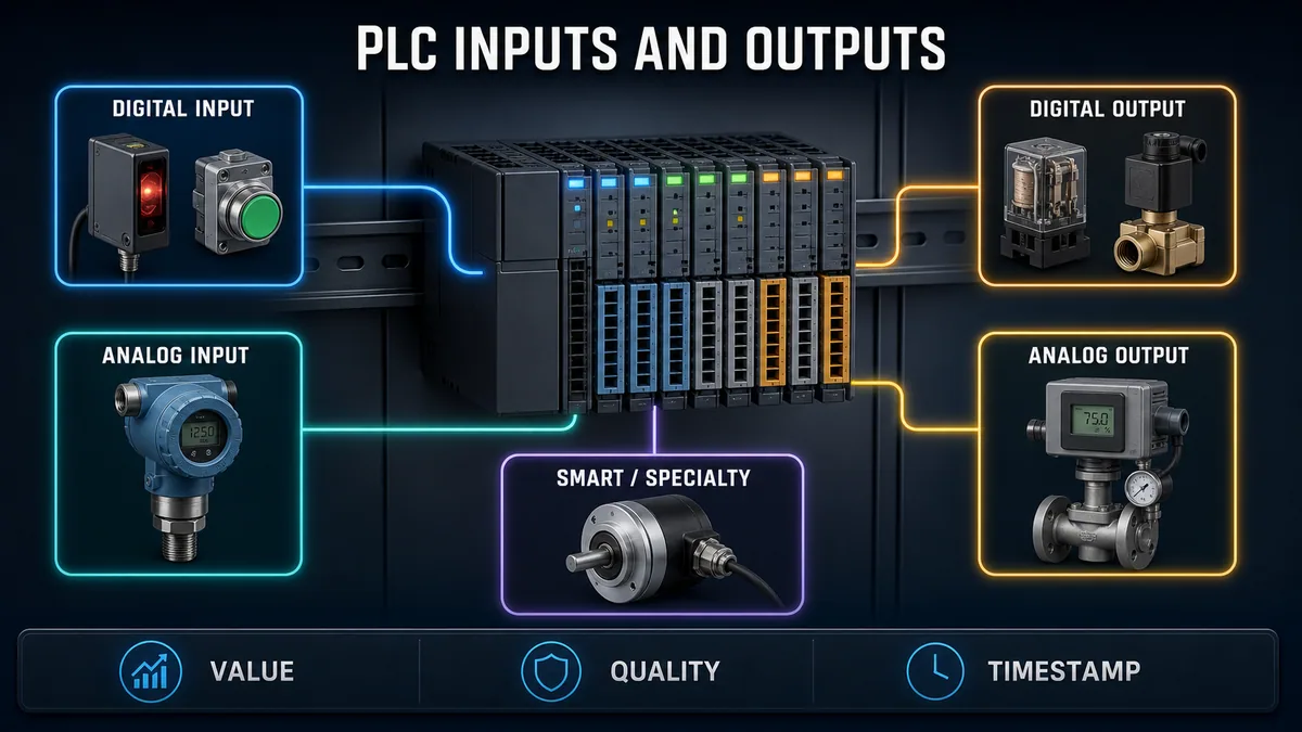
PLC inputs and outputs (I/O) are the controller's boundary with field devices. An input module converts a physical or communicated condition into controller data; the program evaluates that data; an output module converts a controller command into a field signal for an actuator or downstream device. A complete I/O point includes more than a bit or number: service, signal type, electrical interface, range and units, source or load, module/channel, power group, filtering and update behavior, quality/diagnostics, normal and failure behavior, tag mapping, drawing reference and acceptance test.
Use a digital input for a qualified two-state condition such as a pushbutton, auxiliary contact or switching sensor. Use a digital output for an on/off command to a compatible relay, indicator, valve pilot or interface. Use an analog input for a continuous measurement such as current, voltage, resistance or thermocouple signal. Use an analog output for a continuous command such as a valve position or drive reference. Select specialty, smart or safety-rated I/O when standard channels cannot provide the required timing, event capture, signal conditioning, device diagnostics or certified safety behavior.
Select the exact module from the field requirement outward. Verify signal and sensor type, voltage/current/range, thresholds, channel and group limits, isolation, protection, inrush/leakage, accuracy/resolution, filter and conversion time, cyclic or event update, diagnostics, environment, certifications and fail-state behavior. A correct point count with an incompatible interface is not a valid I/O design.
Wire only from the approved system drawings and exact module manual. The PLC wiring and circuit-diagram guide explains how to trace source, switching element, receiver or load and return across schematic and connection views. Separate field/load supply from PLC electronics or backplane power; document commons, groups, isolation and protection; engineer shielding, bonding and cable segregation; and never infer terminals or conductor colors from a generic diagram. Commission each point end-to-end: identify the field device, prove the field condition through the terminal and module, compare raw value plus quality, verify scaling/tag/logic, exercise the authorized output path, observe independent feedback, record diagnostics and update the as-built I/O list.
Understand the complete I/O signal chain
Separate physical quantity, signal and controller data
Pressure is a physical quantity. A transmitter may convert it to a configured current signal. An analog input channel measures that signal and represents it as raw counts or engineering data with status. The program may scale, validate and use the measurement. A controller command may then become an analog output signal for a valve positioner, while a separate position measurement confirms what the actuator actually did.
Those are different boundaries. A valid raw input does not prove the scaled value is correct. A correct output tag does not prove the channel produced a compatible signal. A produced signal does not prove the actuator moved. A feedback value does not prove the command caused it unless identity and timing are also established.
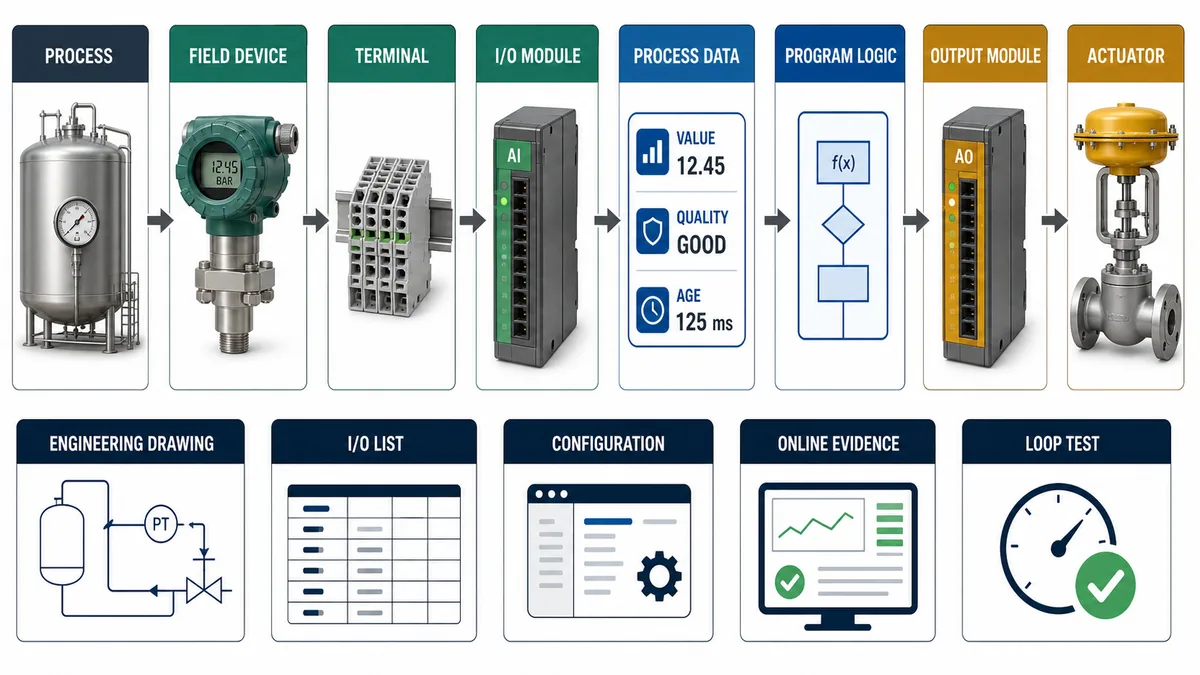
| Boundary | Design record | Runtime evidence | Frequent category error |
|---|---|---|---|
| process | quantity, normal range, operating modes and hazard consequence | independent physical reference and time | treating a tag as the process itself |
| field device | device identity, supply, output/input type, range and diagnostics | local state, calibrated output, device status | calling every transmitter “4–20 mA” without its exact wiring mode |
| cable/terminal | cable/core, junctions, terminals, protection, shield/bonding and isolation | continuity/identity and approved loop evidence | using a generic color or terminal convention |
| I/O channel | module catalog/revision, channel, group, range, filter and diagnostics | raw data, quality/status, module/channel state | reading a plausible number while quality is invalid |
| controller data | tag, datatype, scale, unit, age and ownership | mapped raw/engineering values and timestamp | scaling twice or losing sign/status bits |
| program | validation, mode, permissive, command and failure response | executing logic and first-out reason | forcing a value to hide a design mismatch |
| output path | command, module signal, load/interface and feedback | command, output echo/status and independent result | output image equals energized actuator |
Carry value, quality and age together
A Boolean or number alone is incomplete process data. Quality states whether the producer considers it valid; age or timestamp indicates freshness; diagnostics explain abnormal conditions such as open load, underrange, overrange, field-power loss or synchronization error where supported. Siemens' S7-1500 diagnostics documentation, for example, describes optional channel value status in the process image synchronized with user data. Beckhoff process-image documentation commonly exposes values with error, underrange/overrange, synchronization or update-status information for applicable terminals.
Define how every consumer behaves when quality is bad or age exceeds its limit. Holding the last value can hide a failed sensor. Substituting zero can look like a real low measurement. Driving maximum can create the opposite hazard. The process and hazard review owns the response; the I/O module only provides capabilities and evidence.
Choose digital, analog or specialty I/O
Classify the information and action required
Start with the control requirement, not a preferred card. Ask whether the point is a two-state condition, a continuous quantity, a time-critical pulse/event, a structured smart-device exchange, or part of a safety function. Then identify direction from the PLC viewpoint: an input brings data into the controller, while an output carries a controller command outward.
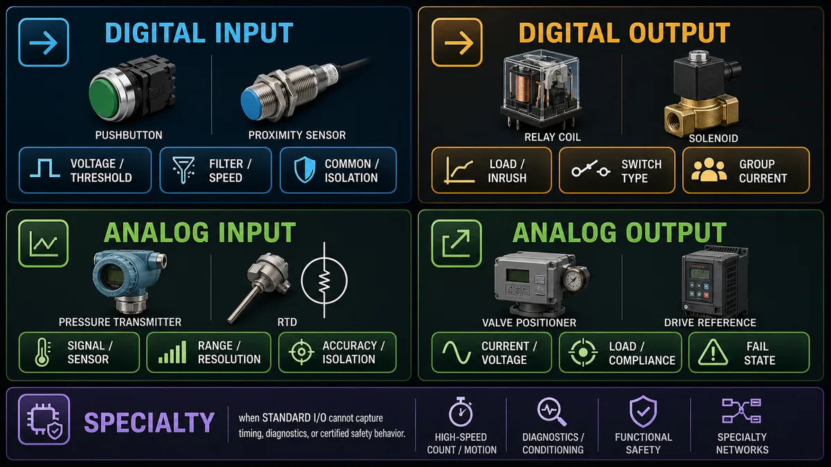
| Requirement | Typical I/O class | Examples | Selection questions |
|---|---|---|---|
| two-state field condition | digital/discrete input | contact, photoeye, proximity switch, relay status | thresholds, source/sink compatibility, filter, common, isolation, diagnostics |
| on/off field command | digital/discrete output | pilot relay, lamp, solenoid interface, enable | load type, inrush, leakage, switching frequency, channel/group current, fault state |
| continuous measurement | analog input | pressure/current, voltage, RTD, thermocouple | signal/sensor, active/passive loop, range, resolution, accuracy, isolation, conversion/filter |
| continuous command | analog output | valve position, drive speed reference, setpoint | current/voltage, load/compliance, resolution, update, isolation and failure response |
| pulse/count/precise event | high-speed or timestamped input | encoder, flow pulse, registration mark | maximum frequency, minimum pulse, timestamp resolution, task/event interface |
| pulse/PWM/scheduled action | specialty output | timed valve pulse, PWM heater, scheduled event | time base, jitter, load compatibility and cycle limits |
| smart point-to-point device | IO-Link or supported smart I/O | parameterized sensor, identification and diagnostics | master port mode, process data layout, device identity, IODD/profile, events and replacement policy |
| safety function | safety-rated controller and I/O subsystem | emergency stop, guard, light curtain, safe output | risk assessment, architecture, diagnostic coverage, response time, certification and validation |
Do not substitute standard I/O for a special requirement
A standard digital input can miss a pulse shorter than its filter and update path. A standard analog input may not support the sensor excitation, cold-junction compensation, lead compensation, isolation or diagnostic behavior a thermocouple or RTD installation needs. A normal output bit does not create a safety function, regardless of how carefully the ladder logic is written.
Choose a high-speed counter, timestamp module, weighing module, temperature module, motion interface, HART/IO-Link master or safety-rated I/O when the requirement demands it. Confirm the complete system, not only the module label: compatible base/terminal, firmware, engineering tool, CPU, network adapter, power architecture, device description/profile and environmental/certification constraints.
Treat IO-Link as structured I/O, not a generic fieldbus claim
The IO-Link Community describes IO-Link as an IEC 61131-9 point-to-point communication technology for sensors and actuators, not a fieldbus. Its system description separates cyclic process data from on-request parameters/identification and events, with the master mediating access. That richer data can improve diagnostics and replacement, but the PLC integration still needs an exact port mode, process-data layout, value status, device identity and parameter-management policy.
Do not reduce a smart sensor to one Boolean if its quality, contamination warning or identity is necessary for the application. Conversely, do not introduce a smart interface when a simple qualified contact meets the requirement more reliably. Select from lifecycle need, not novelty.
Specify digital input channels
Match the field device and input circuit
Digital inputs have documented ON/OFF thresholds, input current, delay/filter, common/group arrangement, isolation, leakage tolerance, permitted sensor types and environmental limits. A contact input, two-wire electronic sensor and three-wire transistor sensor impose different interface conditions. The module may source or sink current, support configurable polarity, or require a matching field interface.
The sinking and sourcing PLC I/O guide owns the detailed PNP/NPN and current-path explanation. The essential rule here is to prove a complete compatible loop from the exact field device output through supply/common and module input—not to match labels by habit.
| Digital-input attribute | Requirement to record | Why it matters |
|---|---|---|
| nominal signal and thresholds | exact device output states versus module ON/OFF regions | a voltage present may still be indeterminate or below ON threshold |
| input current/load | current required from switch/sensor and effect on leakage | two-wire sensor can leak enough current for false ON |
| common/group topology | shared reference, potential group and isolation boundary | wrong common can disable a group or create backfeed |
| filter/delay | OFF-to-ON and ON-to-OFF filter behavior | suppresses chatter but can miss short valid events |
| channel diagnostics | wire-break, short, chatter, value status or none | application must know what the selected module can actually detect |
| timestamp/COS | cyclic, change-of-state, event or timestamp support | determines ordering and minimum observable event |
| field power monitoring | supply/status evidence for input group | CPU can be healthy while field inputs lose supply |
| fault behavior | value/status when circuit, module or connection fails | false, retained or invalid must not be guessed |
Distinguish contact philosophy from PLC logic symbols
A normally open or normally closed field contact describes its physical contact state in a defined normal condition. An examine-if-true or examine-if-false instruction describes how program logic evaluates a Boolean. They are not the same choice. Document the field device de-energized and energized states, normal process condition, broken-wire consequence, input bit convention and application meaning independently.
For critical alarms or interlocks, design failure detectability rather than assuming “normally closed is fail-safe.” A short circuit, cross-connection, welded contact or common failure can defeat a simplistic assumption. Safety functions require their validated safety architecture.
Specify digital output channels and loads
Select the switching technology from the load
Relay, transistor and AC solid-state/triac outputs differ in voltage type, switching speed, leakage, lifetime, isolation, diagnostics and load compatibility. A relay contact may handle AC or DC within its exact utilization limits but has mechanical wear and finite switching life. A transistor output is fast and DC-specific with polarity and semiconductor leakage/voltage-drop considerations. A triac-style output is AC-specific and can have holding/leakage constraints.
Verify steady current, inrush, duty cycle, switching frequency, power factor, inductive energy, ambient derating, per-channel limit, group/module aggregate, common/field supply, protection, permitted suppression and failure mode. “0.5 A output” never proves a 0.4 A coil is acceptable if inrush, group load, repetition or inductive turn-off exceeds another limit.
Calculate output demand before choosing the module
For a worked example, assume the authorized worst-case operating state can energize four interposing-relay coils at 0.040 A, six solenoid pilot coils at 0.120 A, and two indicators at 0.025 A. These are example load data, not typical ratings:
| Load class | Quantity | Assumed steady current each | Subtotal |
|---|---|---|---|
| interposing-relay coil | 4 | 0.040 A | 0.160 A |
| solenoid pilot coil | 6 | 0.120 A | 0.720 A |
| indicator | 2 | 0.025 A | 0.050 A |
| simultaneous steady demand | 12 | — | 0.930 A |
The arithmetic is 4 × 0.040 + 6 × 0.120 + 2 × 0.025 = 0.930 A. If this project deliberately requires a 25% steady-state design reserve, the planned field-supply contribution becomes 0.930 × 1.25 = 1.1625 A before adding other consumers. Round and select under the project's electrical design rules.
That result does not select a module or supply. Compare each load's inrush and suppression with the per-point rating; distribute the simultaneous load across documented groups; apply ambient and duty derating; include module/base and conductor/protection constraints; include supply startup and other loads; and verify the protective device coordinates with the conductors and module. A spare channel can be unusable if its group is already at a limit.
Separate command, output echo and physical result
Rockwell's 2025 ControlLogix digital I/O manual documents capabilities such as output data echo, field-power-loss detection, electronic fusing, no-load detection and field-side output verification for applicable modules. These are distinct evidence surfaces and not every module provides them. Output echo generally establishes module-reported state under its documented model, not current through the load or actuator motion.
Use independent feedback where the process requires proof: auxiliary contact, valve position, drive running state, pressure/flow response or another suitable measurement. Define discrepancy timing and alarm behavior. Do not force the output to resolve whether field power, protection, wiring or the load is at fault; use the PLC I/O troubleshooting guide for the ordered diagnostic method.
Live mini-lab
Try it: press START, then STOP
A stop-dominant seal-in rung: START latches the motor output through its own contact, and STOP breaks the circuit.
Watch the output lamp: it stays on after START until you press STOP.
Free · no signup to try · runs in your browserOpens plcsimulationsoftware.com — same team
Specify analog input and output channels
Match signal, sensor and channel configuration
Analog modules may accept current, voltage, resistance, RTD, thermocouple, strain/bridge or other specialized signals. Verify active versus passive current loop, supported sensor/wiring mode, input impedance, common-mode limits, isolation, range, conversion/update time, filter, overrange/underrange, wire-break behavior, resolution, accuracy, drift and environmental limits. For outputs, verify signal range, load/compliance, short-circuit behavior, update time, resolution and configured fault response.
Resolution is the smallest represented step under stated configuration; accuracy is closeness to the true value within specified conditions. Noise-free display digits do not improve module accuracy. System accuracy also includes field sensor, transmitter, reference/excitation, wiring, isolation, module, scaling and calibration uncertainty.
The PLC analog I/O signals guide owns loop topology, raw/status handling, scaling, quality and detailed analog fault diagnosis. This page shows how the analog point fits into the wider I/O design.
Work a transparent scaling example
Assume a deliberately configured analog input representation—not a universal vendor format:
RawLow = 0at the configured low signal;RawHigh = 32000at the configured high signal;EngLow = 0 °C;EngHigh = 100 °C;- current raw sample
Raw = 16000with good quality.
Use the linear relationship:
Engineering = EngLow + (Raw − RawLow) × (EngHigh − EngLow) / (RawHigh − RawLow)
The result is 0 + (16000 − 0) × 100 / 32000 = 50.0 °C. The nominal represented increment is 100 / 32000 = 0.003125 °C per count. That increment is not the system accuracy and does not prove the sensor or module can resolve a meaningful process change that small.
For an analog output using the same assumed 0…32000 raw span for a configured 4…20 mA range, a 65% command gives Raw = 0 + 0.65 × 32000 = 20800. The corresponding ideal current is 4 mA + 0.65 × 16 mA = 14.4 mA. Verify the exact module representation, clamping, fault value, load/compliance and real measured output; never copy these counts into an unidentified module.
Decide bad-quality and out-of-range behavior explicitly
Separate raw value, engineering value, quality, age, alarm state and control validity. An overrange value may still provide diagnostic magnitude; a wire-break code may lie outside normal raw span; a stale last-good value can look plausible. Preserve raw/status evidence and prevent generic scaling from turning a diagnostic code into a believable process number.
| Input condition | Data model should expose | Application decision owned by design |
|---|---|---|
| valid in range | raw, engineering value, good quality, age | normal display/control use |
| configured underrange/overrange | raw, limit status, derived engineering indication | alarm, clamp, diagnostic or controlled-mode response |
| wire break/open loop if detectable | diagnostic code/status and bad quality | defined fallback, trip/hold/manual transfer and operator response |
| stale/no update | last value plus bad/stale quality and age | maximum age and consequence by consumer |
| module/connection fault | module/channel identity, quality and event | inhibit/transfer/recovery behavior |
| maintenance/calibration mode | substituted/test source, owner and expiry | prevent silent use as normal measurement |
Design addresses, tags and the process image
Keep physical address and semantic tag traceable
A physical address identifies rack/drop, slot/module and channel under a platform's mapping. A semantic tag tells humans and applications what the point means. Preserve both through the I/O list and configuration: PIT_101_PV is more durable than scattering a raw address across logic, while the mapping still proves exactly where the value originates.
Use typed channel structures where practical: raw value, engineering value, quality, age/timestamp, diagnostics, simulated/substituted state, configuration identity and source. For outputs, separate requested command, selected owner/mode, limited command, module command, output status/echo and independent feedback. That model makes commissioning and fault diagnosis extractable without watching dozens of disconnected bits.
Treat the cyclic process image as a model, not a universal law
Siemens' 2024 S7-1500 system manual describes its process image as a consistent memory image of signal states, with documented cyclic transfer between output modules, input modules and the process images. Rockwell ControlLogix I/O documentation describes requested packet interval, cyclic/change-of-state transfer and asynchronous relationships. Beckhoff EtherCAT terminals expose PDO/process-image structures whose content depends on device and configuration. These are not one universal scan mechanism.
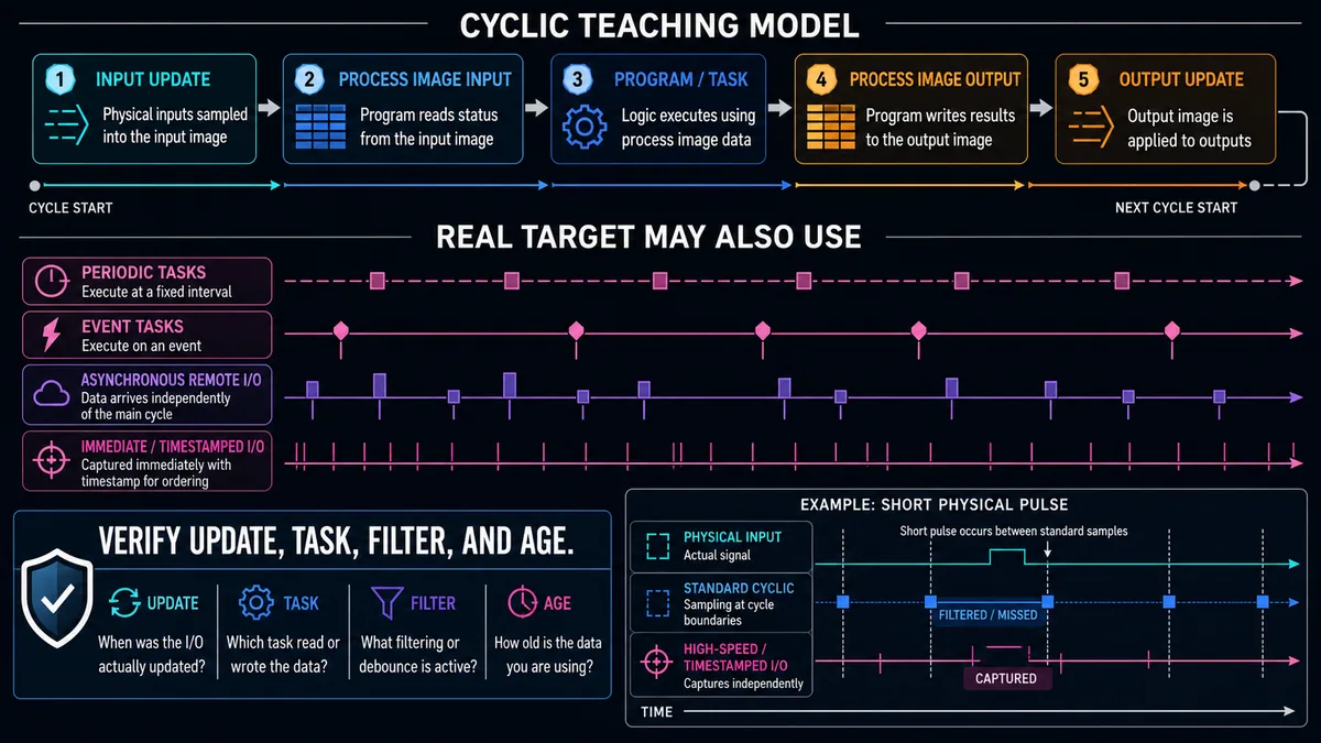
| Timing element | Source of delay or uncertainty | Evidence to specify/test |
|---|---|---|
| sensor/actuator | device response, switching jitter, mechanical/process lag | product response and observed field behavior |
| input conditioning | debounce/filter, conversion, averaging | configured values and pulse/step response |
| module/network | cyclic interval, COS/event, timestamp, bus phase and retries | module/adapter configuration and capture |
| task/program | period, priority, phase, execution and overlap | task monitor/trace and worst-case path |
| output transfer | output update/scheduling and module processing | command-to-module timestamp/capture |
| load/process | relay/valve/drive/machine response | independent feedback and acceptance window |
Work a response-time budget
Assume an example requirement says a permitted event must produce verified actuator response within 100 ms. The selected path has documented or measured worst-case contributions of 12 ms sensor response, 8 ms input filtering, 10 ms network/update wait, 20 ms task wait plus execution, 10 ms output update and 60 ms actuator response. The additive conservative budget is 12 + 8 + 10 + 20 + 10 + 60 = 120 ms.
The candidate fails the 100 ms requirement by 20 ms before other uncertainty is added. Do not simply reduce a filter that was selected for noise immunity. Revisit the requirement and architecture: faster field device, suitable filter, higher-rate update/task, event/timestamp path, specialty output, actuator or another approved design. Then measure the complete path under worst-case representative load. Not all delays are independent or strictly additive; the chosen budgeting method must match the architecture.
Plan field wiring, power and isolation boundaries
Distinguish system power from field/load power
PLC electronics/backplane power and field-device/load power can be separate even when they share a cabinet. A controller can remain in RUN while a field supply is absent. An output indicator can change while the load has no field power. Conversely, a field circuit can remain energized when a PLC module is removed or the CPU is stopped. Draw and label every source, disconnect, protection boundary, common/reference, backfeed path and stored-energy source.
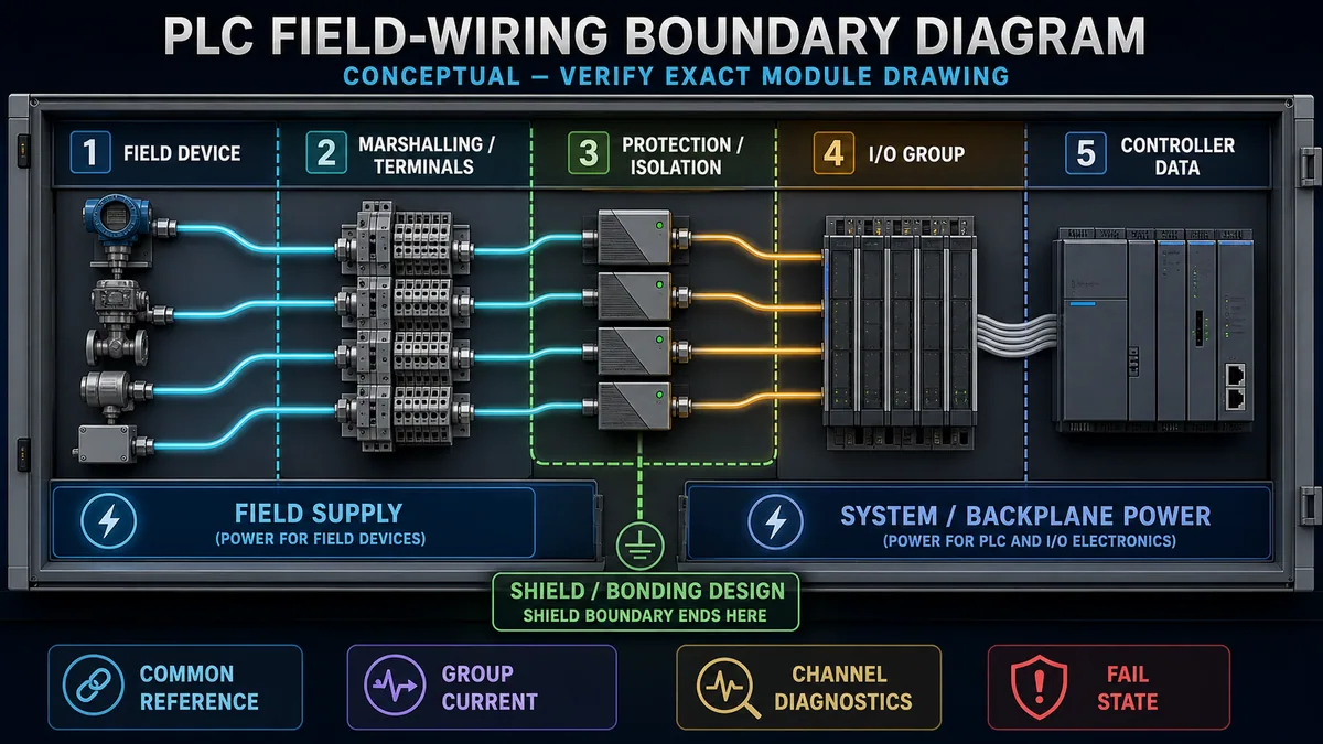
| Wiring boundary | Drawing/design questions | Commissioning evidence |
|---|---|---|
| field supply | source, voltage/type, capacity, protection, isolation and monitoring | identified source and status under representative load |
| system/backplane power | supply capacity, module demand and distribution | configured rack/station healthy with valid budget |
| common/reference | which channels/groups share a reference and where it is established | no undocumented bridge, backfeed or floating path |
| terminal/marshalling | cable/core, terminal identity, disconnect/test feature and segregation | point-to-point identity matches as-built drawings |
| protection/interface | fuse/electronic protection, relay/barrier/isolator and suppression | compatible device and defined fault indication/recovery |
| shield/bonding | cable construction, termination and equipotential/grounding design | installation matches engineered EMC design |
| I/O group | channel allocation, common, group current and diagnostics | channel/group status under authorized test |
Engineer grouping, segregation and protection
Group channels by voltage/signal type, common/reference, isolation, equipment ownership, failure consequence and maintenance boundary—not only by spare space. Do not mix circuits on a terminal/module simply because the conductors fit. Follow product spacing, potential-group, hazardous-area, intrinsic-safety, EMC, cable-rating and enclosure requirements.
Coordinate conductor capacity and protection with available fault current, field supply, module and load. Electronic short-circuit protection has current, time, temperature and retry behavior; it is not a universal substitute for branch protection. Suppression for inductive loads changes release time and must match the module/load and functional requirement. Use exact manufacturer instructions and the engineered electrical design.
Establish the safety boundary before live work
OSHA 1910.333 generally requires exposed live parts to be de-energized unless the stated conditions and protections apply, and it requires qualified persons for covered energized work. OSHA 1910.147 addresses hazardous-energy control during covered servicing and states that pushbuttons, selector switches and interlocks are not energy-isolating devices. The site's applicable rules and risk assessment determine the work method.
An I/O LED, HMI status or output force is not absence-of-voltage verification. This guide does not authorize energized probing, terminal work, bypasses, forces, hot swap or safety-function testing. Only qualified, authorized people using the site's drawings, permits, energy-control and electrical safe-work procedures should perform installed-equipment work.
Build an auditable I/O list and channel schedule
Give every point enough attributes to survive handover
An I/O list is a design and test database, not four columns of tags. Keep stable identifiers and controlled revisions. Separate functional requirement from hardware allocation so a module change does not erase what the point must do.
| Attribute group | Recommended fields | Decision supported |
|---|---|---|
| identity | tag, service/description, equipment, area/unit, requirement ID | what the point means and why it exists |
| I/O class | DI/DO/AI/AO/specialty/safety, signal/sensor type, direction | correct interface family |
| field details | device, normal/de-energized states, range/unit, source/load, supply | compatibility and behavior |
| electrical boundary | drawing, cable/core, junction/terminal, common/group, isolation/protection | traceable field wiring |
| allocation | station/rack, slot/module, channel, base/terminal, configured address | hardware and data mapping |
| performance | filter, conversion/update, accuracy/resolution, response budget | timing and measurement fitness |
| data model | raw tag, engineering tag, datatype, scale, quality, age and owner | usable controller data |
| abnormal behavior | diagnostics, failure state, alarm/interlock, substitution policy | safe and diagnosable response |
| lifecycle | spare/reserve class, calibration, test ID/status, revision and approver | commissioning and maintenance evidence |
Calculate point count, reserve and module quantity
Assume a defined project scope requires 37 DI, 22 DO, 9 AI and 5 AO. The project specification requires a 20% planning reserve for each class; this percentage is an explicit project assumption, not a universal rule.
| Class | Required | × 1.20 then round up | Candidate density | Modules | Installed channels | Unallocated after reserve target |
|---|---|---|---|---|---|---|
| DI | 37 | 45 | 16 | 3 | 48 | 3 |
| DO | 22 | 27 | 16 | 2 | 32 | 5 |
| AI | 9 | 11 | 8 | 2 | 16 | 5 |
| AO | 5 | 6 | 4 | 2 | 8 | 2 |
The formulas are ReserveTarget = ceil(Required × 1.20) and Modules = ceil(ReserveTarget / ModuleDensity). The arithmetic establishes capacity only. Before accepting the schedule, distribute points across common/potential groups, load/current limits, isolation zones, cabinets/stations, network capacity, power budget, safety classifications, redundancy/availability and maintenance spares. Sixteen open DI channels on an inaccessible remote station do not necessarily satisfy a local reserve requirement.
Mark spare, reserved and future points differently
A physically unused channel may be spare capacity, reserved for a named requirement, unavailable because of group/power/isolation constraints, or unsuitable for the signal. Give each a status. Provide terminal and cable capacity only where the design intentionally includes it; undocumented “future” conductors become ambiguity during commissioning.
Configure failure behavior and diagnostics
Define output states by consequence
On controller stop, connection loss, module fault or field-power loss, an output may de-energize, hold, adopt a configured value, follow a delayed fault state or behave according to another product-specific mechanism. None is universally safe. Closing a cooling valve, opening a fuel valve, stopping a lubrication pump and freezing a motion reference have different consequences.
Record the initiating failure, detection time, module behavior, field interface behavior, actuator fail action, process response, restart/reconciliation and independent protection. The safety or process hazard review owns the required state. Verify that the exact hardware and configuration implement it, including what happens before the module detects the fault and after communications return.
Expose diagnostic limits
Module features vary. Rockwell's current digital I/O manual documents optional/configurable behaviors such as input filters, COS, output echo, electronic fusing, field-power-loss, no-load and field-side verification on applicable modules. Siemens documents channel diagnostics and value status on applicable modules. Beckhoff examples show process-data objects whose diagnostic content depends on the selected device/PDO assignment. Schneider documentation similarly exposes module-specific status where enabled or read through the supported interface.
Do not write “channel diagnostics” in the I/O list without naming what is detected, under what output/input state, with what threshold/time, and how the application obtains it. Open-load detection may work only when an output is off or on, depending on product. A disabled diagnostic is not evidence of health.
Commission every input and output point
Test from field condition to accepted evidence
Prepare approved loop-test sheets from the controlled I/O list and drawings. Verify prerequisites, identity, calibration/reference status, safe process condition, responsible operator and abort criteria. Record as-found before changing configuration. Where live simulation or output action is not permitted, use an approved isolated method or defer the test; do not improvise a force.
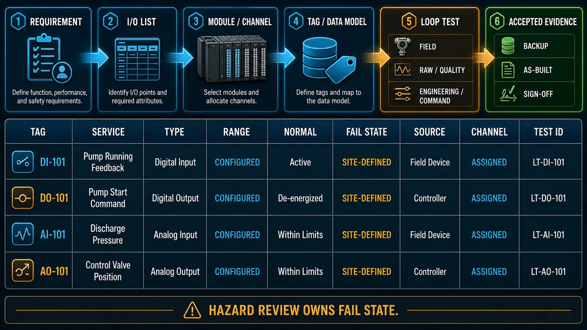
| Point class | Authorized stimulus/condition | Controller evidence | Output/process evidence | Acceptance record |
|---|---|---|---|---|
| DI | field device/contact normal and active states | raw bit, mapped tag, quality, filter/timestamp if required | application state changes only as specified | both states, identity, timing and diagnostics |
| DO | approved command through normal ownership | requested/selected/final command, output status/diagnostics | channel signal and independent load/actuator result | on/off, discrepancy, protection and restoration |
| AI | traceable low/mid/high plus authorized abnormal points | raw/status, engineering value, quality and age | display/control/alarm behavior | errors, tolerances, units and calibration reference |
| AO | approved low/mid/high commands within safe process boundary | requested/limited/raw output and status | traceable signal plus actuator/device response | output error, load response and failure-state test |
| specialty/smart | profile-specific vectors, identity and event cases | process data, status/events, timing and parameters | device operation/diagnostics | configuration/version and supported test matrix |
Prove analog points at more than one value
Low and high points reveal span and reversal errors; a midpoint reveals offset/linear mapping errors that two endpoints can hide in some workflows. Include quality and configured overrange/underrange or diagnostic conditions where safely supported. Use a traceable source appropriate to the required uncertainty and document tolerances before testing.
For analog outputs, distinguish raw command, actual electrical signal, receiving-device interpretation and physical response. A correct 14.4 mA signal can still produce the wrong valve position if the receiver range, action, characterization or mechanical linkage differs.
Close discrepancies and update as-built records
Record every wiring, allocation, range, filter, scale, tag, diagnostic and fail-state change through the controlled process. Retest affected normal, boundary, fault and restart behavior. Update drawings, I/O list, configuration, source project, calibration and loop-test records together. A redlined drawing that never reaches the master is future troubleshooting debt.
At handover, verify no unintended force, test value, simulation flag, bypass or temporary jumper remains. The PLC program debugging guide owns safe online-monitoring, trace and force governance. Archive the final online/offline comparison and backed-up project with the accepted hardware/configuration identity.
Troubleshooting sequence by symptom
Locate the first failed boundary before replacing hardware
| Symptom | First decisive comparison | Likely boundary if it first diverges | Avoid |
|---|---|---|---|
| field device active, PLC bit off | physical device/terminal state versus module LED/raw bit/quality | wiring, common/supply, compatibility, filter or channel | rewriting logic |
| module LED on, mapped tag off | raw channel/address versus mapping and project identity | addressing, mapping, connection or data ownership | rewiring a proven field loop |
| analog value fixed low/high | field reference and raw/status versus configured range | field circuit, range/type, wire break or diagnostic code | adjusting scale to hide raw error |
| output tag true, load off | final command/force versus module status, field power and channel signal | output ownership, module, group supply/protection or load path | forcing repeatedly |
| several points fail together | shared supply/common, group/module, remote station and connection | common/group/power/network boundary | replacing every device |
| short pulse missed | physical event duration versus filter, update, task and timestamp support | timing architecture | reducing filter without noise review |
| point fails after module replacement | exact catalog/revision, base, configuration, range and channel mapping | compatibility/configuration | assuming same channel count means equivalent module |
| output behaves unexpectedly on network loss | configured fault state, detection delay, interface and actuator fail action | failure-behavior design/configuration | calling de-energized universally safe |
| value plausible but wrong | source, raw, quality, scale, unit and duplicate conversion | data model/scaling | calibration offset as first fix |
| safety input visible in standard PLC | validated safety path and status versus standard mirrored tag | safety interface/diagnostics | treating the mirrored bit as proof of safety function |
Diagnostic answer map for PLC inputs and outputs
| Question a technician or AI assistant may ask | Short, extractable answer | Evidence that decides it |
|---|---|---|
| What are PLC inputs and outputs? | Inputs convert field conditions into controller data; outputs convert controller commands into field signals, with mapping, quality, timing and failure behavior around each point. | I/O list, module configuration and loop-test evidence |
| What is the difference between digital and analog PLC I/O? | Digital I/O represents qualified two-state conditions or commands; analog I/O represents continuous measurements or commands over a configured range. | field requirement and exact channel specification |
| How do I choose a PLC I/O module? | Match signal, electrical interface, channel/group limits, isolation, timing, diagnostics, environment, fail state and system compatibility—not only point count. | field-device data, load list, timing budget and module manual |
| How many PLC I/O modules do I need? | Apply the project's reserve to each I/O class, divide by suitable module density and round up, then validate group, power, isolation, location and network constraints. | controlled I/O list and channel schedule |
| What is a PLC process image? | It is a platform-specific controller data representation of I/O states used under documented update rules; it is not a universal physical or timing guarantee. | controller/module update documentation and task configuration |
| Does a PLC output bit prove the device is on? | No. Trace final command, module status/signal, field power, interface/load and independent actuator feedback. | online evidence plus approved field/feedback test |
| How do I scale a PLC analog input? | Map the valid configured raw span linearly to engineering low/high while keeping quality and diagnostic codes separate. | exact raw representation, range, units and traceable test points |
| What should a PLC output do on failure? | The site hazard and process design must define it; de-energize, hold or substitute are not universally safe. | hazard review, module configuration, actuator fail action and test |
Continue into sensor-specific I/O design
Use the photoelectric sensor types guide for through-beam, retroreflective, diffuse, background-suppression and application boundaries around a discrete input. Use the pressure, flow and level measurement guide for analog transmitter ranges, units, scaling, quality and loop evidence. When the task includes terminal layout, segregation, protection and drawing handoff, continue to the PLC control-panel wiring guide.
Frequently asked questions
What is a PLC input?
A PLC input is a channel or communicated data object that brings a field condition into the controller. It can be a digital state, analog value, pulse/count, timestamped event or structured smart-device record. A usable input also needs identity, quality, age, configuration and mapping.
What is a PLC output?
A PLC output carries a selected controller command toward a field device through a compatible channel or communications object. The program command, module-reported state, electrical signal, actuator result and feedback are separate evidence boundaries.
What is the difference between a digital input and digital output?
A digital input reads a qualified two-state field condition into the PLC; a digital output switches a compatible two-state command outward. Direction is always from the controller viewpoint. Each still requires compatible voltage/current topology, group/common, timing and diagnostics.
What is the difference between analog input and analog output?
An analog input converts a continuous field signal or sensor value into controller data. An analog output converts a controller number into a continuous field command. Their ranges, raw representations, accuracy, isolation, quality and failure behavior must be configured and tested separately.
How do I calculate PLC I/O count?
Count each required point by class, apply the project's explicit reserve, round up to suitable module densities, then validate grouping, current, isolation, station location, power, network capacity and safety classification. An unused physical channel is not automatically a usable spare.
Can I connect a solenoid directly to a PLC output?
Only if the exact solenoid steady/inrush current, voltage type, inductive behavior, duty and suppression comply with the exact output's per-channel, group, protection and environmental limits. Otherwise use an engineered compatible interface. Verify the circuit design and manufacturer instructions.
What does PLC input filtering do?
Input filtering rejects or delays changes shorter than the configured behavior, which can reduce chatter/noise but also miss valid pulses and add response time. Select it from signal characteristics and the timing budget; use high-speed or timestamped I/O when required.
What is the PLC input image and output image?
They are platform-specific memory/process-data representations used under the controller's documented update model. A simple cyclic model is useful for teaching, but periodic/event tasks, asynchronous networks and specialty I/O can behave differently. Verify the exact target.
Why is my PLC output on but the device is off?
The viewed bit may not be the final writer, a force or mode may alter ownership, the module/channel or field supply may be faulted, protection may be open, or the load/interface may not respond. Trace command, module evidence, field signal and independent feedback in order.
How should PLC I/O be commissioned?
Use controlled drawings and an I/O list, verify identity and prerequisites, test each authorized field state or traceable analog point through raw value/quality and engineering tag, exercise outputs through normal ownership, prove feedback and failure behavior, close discrepancies and update as-built evidence.
Sources, review scope, and limitations
This guide synthesizes primary regulator, standards-community and manufacturer documentation into a vendor-neutral I/O design and commissioning method. The figures are conceptual and do not define compatible products, terminal assignments, conductor colors/sizes, protection, commons, isolation, shield termination, grounding/bonding, hazardous-area circuits, output fail states, safety architecture or live test methods. Exact product instructions and the engineered site design take precedence.
- OSHA 29 CFR 1910.147: The Control of Hazardous Energy — hazardous-energy scope, procedures and limits of control-circuit devices as isolation.
- OSHA 29 CFR 1910.333: Selection and Use of Work Practices — de-energization, qualified-person and electrical safe-work requirements.
- NIST SP 800-82 Rev. 3: Guide to Operational Technology Security — OT safety, reliability, access, change and security context.
- Siemens S7-1500 / ET 200MP System Manual, 11/2024 — process image, I/O system, power architecture and commissioning context.
- Siemens S7-1500 Diagnostics Function Manual, 11/2024 — system/channel diagnostics and quality/value status in process data.
- Siemens DI 16x24…125VUC HF Equipment Manual, 02/2024 — example of module-specific wiring, parameters and technical specifications.
- Rockwell Automation ControlLogix Digital I/O Modules User Manual, 01/2025 — cyclic/COS transfer, filters, output echo, fusing, diagnostics, field-power and fast-I/O features.
- Rockwell Automation ControlLogix I/O Documentation Center — current digital, analog, safety and specialty module documentation routing.
- Rockwell Automation High Resolution Analog I/O Modules User Manual — range-, sensor- and temperature-dependent analog resolution context.
- Beckhoff EtherCAT I/O Terminal Documentation Index — digital, analog, specialty and diagnostic terminal documentation.
- Beckhoff EP4378 Process Image — combined DI, AI, DO and AO process data with status/validity examples.
- Beckhoff Multi-Timestamp I/O Technology — standard sampling, filter and timestamped digital-I/O distinctions.
- Schneider Electric Machine Expert: Analog I/O Module Diagnostics — module/channel status and configuration-dependent diagnostic access.
- Schneider Electric: Configuring I/O Fallback Behavior — product-specific output fallback configuration example.
- IO-Link Downloads and Released Specification Packages — current official interface, device-description, profile, safety and test packages.
- IO-Link System Description — point-to-point architecture, cyclic process data, parameters, identification and events.
Now run it · free · no signup
Wire a 24 VDC sensor to a PLC input
Connect sensor power and signal, present a target and prove the live PLC input changes. Free browser lab — no signup required to finish it.
Ownership disclosure: PLC Programming IO and PLC Simulation Software are operated by the same publisher.
PLC Programming IO Editorial Team
Industrial automation education, references, and software testing
The PLC Programming IO Editorial Team publishes sourced industrial-automation education and documents how material is reviewed, tested, and corrected. A team byline means the publisher is responsible for the page; it does not represent a fictional person or imply an engineering licence.
Coverage:
- • PLC programming concepts and examples
- • Vendor software tutorials and comparisons
- • SCADA, HMI, protocols, and instrumentation
- • Training, careers, and reference material
Review standard:
- • Prefer primary and official sources
- • Record software versions when material
- • Separate tested facts from estimates
- • Publish material corrections
Important scope note
This site provides education, not project-specific engineering approval. Safety, code, and compliance decisions require a qualified person with access to the actual machine and jurisdiction.