Sinking and Sourcing PLC I/O Explained
Match PNP and NPN sensors to PLC inputs, distinguish high-side and low-side outputs, calculate the current path, check electrical limits and troubleshoot safely.
Review status: Editorially reviewed against cited Siemens, Rockwell Automation, Schneider Electric, Beckhoff and OSHA documentation; exact terminals, polarity, thresholds, load ratings, protection, isolation and test methods require product- and site-specific verification
Direct answer
Sourcing means supplying conventional current into a circuit; sinking means providing its return path toward 0 V. A complete 24 VDC input loop needs one side to source and the other to sink. Therefore a PNP sourcing sensor normally drives a sinking PLC input, while an NPN sinking sensor normally drives a sourcing PLC input. For an ON signal, conventional current flows from +24 V through the sourcing side, the input/load and the sinking side to 0 V.
For transistor outputs, a sourcing output is normally a high-side switch that applies positive supply to a load whose other side returns to 0 V. A sinking output is normally a low-side switch that completes the load's path to 0 V while the other side of the load is supplied from +24 V. A relay-contact output is different: its isolated contact can often be placed on either side of a compatible circuit within its ratings, but it does not supply voltage by itself.
Terminology alone is not enough to authorize a connection. Manufacturers can describe the module by its internal current behavior, by the compatible field device, or as positive/negative switching. Some input banks become sinking or sourcing according to how their group common is wired or configured; others have fixed polarity. Read the exact module wiring diagram and specifications, then draw one complete current path from the supply through sensor/contact/input or output/load and back to the supply return.

Start with conventional current, not the label
Conventional current is drawn from the positive supply toward the negative/0 V return. Electron flow is physically opposite, but industrial schematics, component ratings and the words source/sink normally use conventional current.
Identify the sourcing side and sinking side
| Circuit role | What it does when ON | Common implementation | Opposite side needed |
|---|---|---|---|
| source | supplies conventional current from positive potential | PNP/open-emitter sensor output or high-side PLC transistor output | a sinking input/load/return path |
| sink | accepts current and completes path toward 0 V | NPN/open-collector sensor output or low-side PLC transistor output | a sourcing input/supply/load path |
| passive contact | opens or closes a conductor but supplies no electrical energy | pushbutton, relay contact, limit-switch contact | external supply plus input/load and return |
| push-pull/bipolar | actively drives more than one state/direction as specifically designed | product-specific sensor/output stage | only the interface described by its manual |
“PNP” and “NPN” name transistor structures, but in typical three-wire DC industrial sensor shorthand, PNP is the sourcing signal version and NPN is the sinking signal version. Normal-open/normal-closed behavior is a separate choice: a PNP sensor can be NO or NC, and so can an NPN sensor.
Trace the two valid input loops
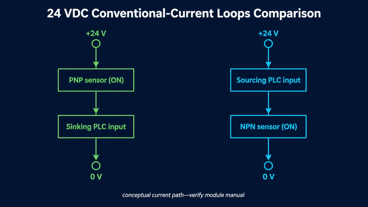
| Sensor/interface pair | ON-state current path | Compatible in the general case? |
|---|---|---|
| PNP sourcing sensor + sinking PLC input | +24 V → sensor output stage → PLC input circuit → input common/0 V | yes, when all voltage/current/common specifications match |
| NPN sinking sensor + sourcing PLC input | +24 V/input common → PLC input circuit → sensor output stage → 0 V | yes, when all specifications match |
| PNP sourcing sensor + sourcing PLC input | both sides expect to source; no intended return through input | no, unless exact product provides a special bidirectional interface |
| NPN sinking sensor + sinking PLC input | both sides expect to sink; no intended positive source through input | no, unless exact product explicitly supports it |
This compatibility rule does not define wire color, terminal number, supply sharing, isolation, safety category or permissible current. Use it to understand the circuit after the exact product documents are open.
Decode PLC input terminology and common polarity
Some DC input groups have a common terminal that can be connected to either 0 V or +24 V, changing the group between sinking and sourcing behavior. Rockwell's MicroLogix 1000 instructions, for example, describe a sinking input as active high with DC COM at negative, and a sourcing input as active low with DC COM at positive. Siemens S7-1200 G2 documents particular configurable input products with the common connected to one polarity for a selected sinking mode and the other polarity for sourcing mode. The exact labels and setup differ, so the module manual controls.
Join four descriptions before deciding compatibility
| Evidence | Example wording | What it tells you |
|---|---|---|
| catalog/module type | 24 VDC sinking input, source input, positive switching |
intended electrical behavior, subject to vendor terminology |
| group wiring diagram | common connected to M/0 V or L+/+24 V | polarity/reference that completes the input circuit |
| electrical table | on/off voltage, on/off current, impedance, delay, IEC input type | whether sensor ON/OFF states are guaranteed |
| field-device output | PNP source, NPN sink, push-pull, two-wire, relay contact | switching role and residual/leakage behavior |
| configuration parameter | sinking/sourcing or positive/ground switching selection | software-selected interpretation/stage behavior where supported |
| channel/group boundary | common per 4/8/16 channels, isolated or shared | which points change together and what supplies/reference they share |
Do not infer a bank common from a nearby M, L+, DC COM, S/S or C terminal on another model. Some module families share one common across a group; some have individual commons; some fixed-polarity M12 blocks supply sensors internally. The catalogue number, base/terminal unit and revision all matter.
Use the common as a compatibility checkpoint
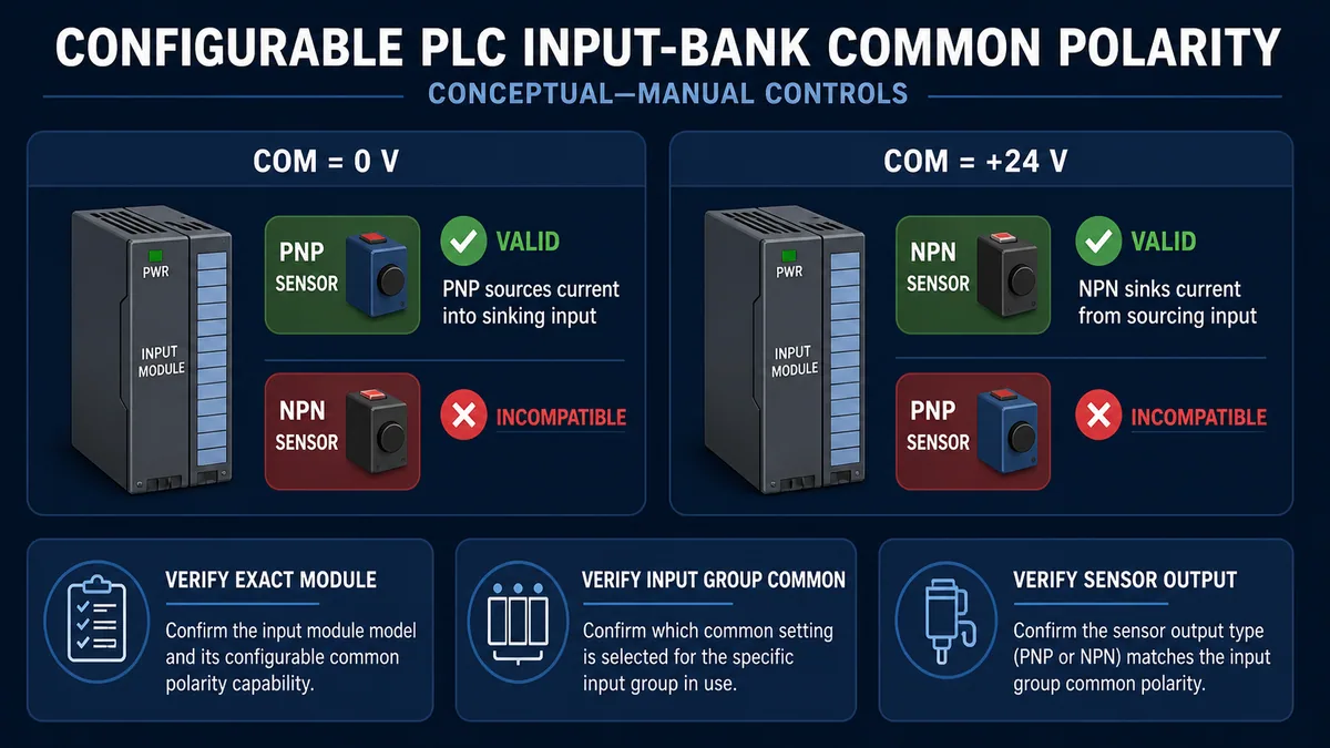
| Input-bank condition | Expected compatible signal | ON state concept | Diagnostic clue |
|---|---|---|---|
| common/reference at 0 V, module documented as sinking | PNP/sourcing signal applies positive voltage/current to input | active high | input terminal approaches positive supply relative to common under supported load |
| common/reference at +24 V, module documented as sourcing | NPN/sinking signal pulls input toward 0 V | active low | input terminal approaches return relative to common under supported load |
| wrong common/open return | neither loop completes correctly | undefined/off/intermittent | several points in same group fail together |
| polarity/configuration mismatch | device output and input role do not complement | no guaranteed valid state | sensor LED can operate while PLC input stays off |
Schneider documentation also distinguishes positive logic—source output into sink input—from negative logic—sink output drawing current from a source input. It notes product-specific consequences such as a ground fault being interpreted as ON in a negative-logic interface. Fault response belongs in the design decision, not only whether a normal signal works.
Connect dry contacts and electronic sensors conceptually
A dry contact has no PNP/NPN transistor and is not inherently sourcing or sinking. Its placement in the powered loop determines which role the external circuit creates.
Distinguish contact, two-wire and three-wire devices
| Field device | Supply conductors | Signal behavior | Compatibility work |
|---|---|---|---|
| dry contact | none for contact itself | connects/disconnects external current path | choose side of input circuit per module diagram and contact ratings |
| three-wire PNP sensor | positive supply, 0 V return, sourcing signal | electronics powered independently; signal sources positive current | sinking input; sensor load/current and commons compatible |
| three-wire NPN sensor | positive supply, 0 V return, sinking signal | electronics powered independently; signal sinks current | sourcing input; current path and references compatible |
| two-wire electronic sensor | two wires in series with input/load | must power its electronics through ON/OFF circuit | check off-state leakage, on-state drop, minimum load/current and polarity |
| push-pull sensor | supply, return, actively driven signal | can drive high and low according to product | use only documented compatible input; check fault/backfeed behavior |
| NAMUR/special interface | product-specific low-energy/current behavior | not a standard 24 V PNP/NPN switch | requires approved barrier/amplifier/input interface |
For a sinking input bank whose common returns to 0 V, a dry contact can complete the positive side from an approved +24 V source to the input. For a sourcing input bank whose common is at +24 V, a dry contact can complete the return side from input toward approved 0 V. This is a conceptual path, not a terminal instruction; isolated supplies, common bonding, protection and channel grouping must follow the project drawing and exact manuals.
Do not trust color without the product diagram
Brown/blue/black is a common three-wire sensor convention for positive supply, 0 V and output, but connectors, complementary outputs, four-wire sensors, special interfaces and repaired cables vary. Read the label/pinout and prove the selected part number. Wire color is supporting evidence, never the compatibility test.
Live mini-lab
Try it: press START, then STOP
A stop-dominant seal-in rung: START latches the motor output through its own contact, and STOP breaks the circuit.
Watch the output lamp: it stays on after START until you press STOP.
Free · no signup to try · runs in your browserOpens plcsimulationsoftware.com — same team
Understand sinking and sourcing PLC outputs
Input terminology asks who drives the sensing circuit. Output terminology asks which side of the load the semiconductor switch controls.
Compare high-side, low-side and relay outputs
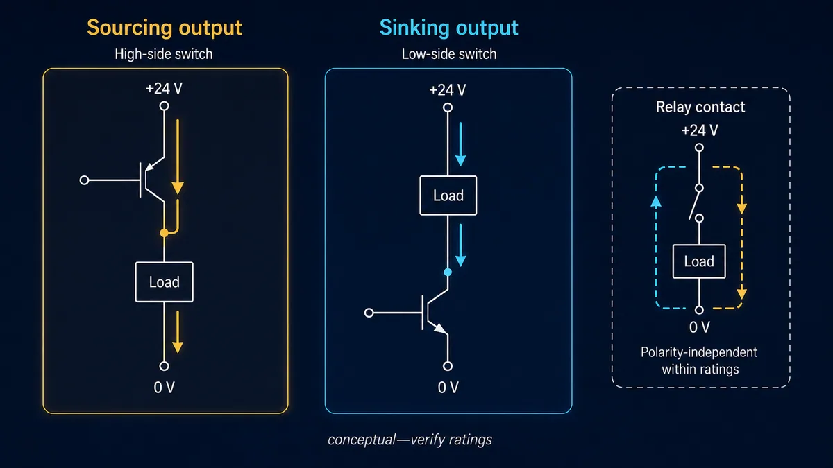
| Output type | ON-state path | Load placement concept | Key limitation |
|---|---|---|---|
| sourcing/PNP transistor | module positive/load supply → high-side output switch → load → 0 V | load between output and return | channel/group current, voltage drop, leakage and supply/reference |
| sinking/NPN transistor | +24 V → load → low-side output switch → module return | load between positive supply and output | same limits plus shared return/common integrity |
| push-pull/bipolar | actively sources and sinks as specified | product-defined load/interface | never parallel or back-drive without explicit support |
| relay contact | external supply → contact → load → external return in allowed circuit | high or low side if contact ratings/application permit | mechanical life, switching category, inrush and no output voltage without supply |
| AC triac/solid-state | AC-specific electronic switching | product-specific AC load | not interchangeable with 24 VDC transistor logic |
The PLC output LED commonly shows the controller's command or channel state, not proof that load power is present or current reaches the actuator. A sourcing bank can need a separate load-supply terminal; a sinking bank needs a valid return; a relay output needs an external supply. Compare command, module diagnostic/status, group supply, output terminal under the approved test and load feedback.
Calculate per-channel and group load before connection
| Rating/behavior | Question | Failure if ignored |
|---|---|---|
| nominal/allowed voltage | are module, supply and load ranges compatible through tolerance? | undervoltage, damage or undefined switching |
| per-channel continuous current | does steady load current remain below channel limit? | overheating, shutdown or output damage |
| group/module total | do simultaneous loads exceed shared terminal/driver/thermal limit? | several outputs fail despite each being individually acceptable |
| inrush/peak | lamp, contactor, valve or capacitive input startup current | nuisance protection or welded/damaged stage |
| on-state voltage drop | voltage remaining for load at actual current | load chatters or will not pull in at supply low limit |
| off-state leakage | current through load while command is OFF | glow, ghost voltage or unintended sensitive-load operation |
| switching rate/duty | thermal and device switching limit | excess heat or shortened life |
| short-circuit protection | exact duration/reset/thermal behavior | assuming “protected” permits indefinite or repeated faults |
Schneider's TM3 output specifications illustrate why all fields matter: the product publishes per-channel and group current, voltage drop, off-state leakage, switching time, short-circuit behavior and clamping. Those numbers are not transferable to another output. Beckhoff likewise documents product-specific leakage that can produce several volts on a high-impedance measurement even when the output is not delivering usable load current.
Use guaranteed input and output electrical limits
Digital does not mean any voltage below 12 V is zero and any voltage above it is one. The manufacturer specifies guaranteed OFF and ON voltage/current regions, with an intermediate region where the logical result is not guaranteed. Input filters add timing behavior.
Create an electrical compatibility worksheet

| Input-module specification | Field-device specification to compare | Pass logic |
|---|---|---|
| guaranteed ON voltage/current range | sensor ON residual voltage/current capability at supply/load extremes | sensor can deliver at least required current while keeping input inside ON region |
| guaranteed OFF voltage/current maximum | sensor off-state leakage and coupled current | worst leakage keeps input inside OFF region |
| nominal input impedance/current | sensor maximum load/current and cable drop | both device and input operate within limits |
| input filter/delay | shortest valid field pulse and bounce/noise behavior | real event persists long enough and nuisance event is rejected |
| polarity/reverse protection | possible field faults and supply references | design does not rely on unspecified reverse behavior |
| isolation/group common | sensor supply and other connected equipment references | no prohibited commoning, ground loop or backfeed path |
Rockwell's current 1762 module instructions, for example, publish minimum on-state voltage/current, maximum off-state voltage/current, impedance and delay for a 24 V sink/source input product. POINT I/O selection data distinguishes fixed sinking and sourcing module variants. Use the exact row for the exact catalogue number—not a family-level nominal value.
Treat two-wire leakage and output ghost voltage as load problems
A high-impedance digital meter can display voltage produced through tiny off-state leakage, internal diagnostic circuits or capacitive coupling. Voltage alone does not prove the output can deliver rated current. Conversely, a two-wire sensor needs some off-state current to power itself, which can keep a sensitive PLC input above its guaranteed OFF current.
Use the manufacturer-approved compatibility calculation or accessory/bleeder interface where specified. A resistor is not a generic fix: its resistance, power, heat, protection, fault behavior and effect on the ON state must be engineered. Do not add one based on an internet value.
Protect outputs and inductive loads correctly
Relays, contactors, solenoids and valve coils store magnetic energy. When current is interrupted, that energy produces a voltage transient. The output's internal clamp/protection and the external suppression recommended for the exact load determine stress and release time.
Select suppression as part of the load design
| Suppression question | Why it matters |
|---|---|
| does the output manual require external suppression despite internal protection? | short-circuit/clamp protection may not absorb repetitive load energy indefinitely |
| what is the load coil voltage, current, inductance/energy and duty? | sizes the suppression and output stress |
| where must the device be installed? | lead inductance can defeat remote suppression; manufacturer placement rules apply |
| what release time is required? | a flyback diode can slow relay/valve release compared with higher-voltage clamps |
| is polarity fixed? | diode suppression is polarity sensitive; wrong polarity can create a short/failure |
| is the device safety/process critical? | release delay and welded/stuck output consequences enter validation |
Beckhoff's guidance explains that an inductive load tries to continue current when the driver turns off and can generate very high self-induced voltage without a dissipation path. Use its/product/load manufacturer calculation—not the conceptual image on this page—to choose diode, TVS, RC or other suppression.
Avoid backfeed, shared-common and ground-fault surprises
A circuit can work in a normal state and still be unsafe or undiagnosable under power loss, broken common or cross-supply faults. Multiple supplies and I/O groups require intentional reference and isolation design.
Review the fault matrix before wiring
| Fault/change | Possible result | Required design evidence |
|---|---|---|
| input common opens | every point in group drops, floats or becomes intermittent | group boundary, monitored supply/common and alarm consequence |
| 0 V is grounded/missing contrary to design | noise, fault current or unintended active-low signal | exact grounding/bonding drawing and product guidance |
| field supply off, signal backfeeds from another source | module/device partially powers through I/O | isolation and every external connection reviewed |
| two outputs tied together | driver contention and damage when states differ | only use supported redundancy/diode/interface architecture |
| output supply missing while external voltage remains | reverse feedback into unpowered module | product prohibition/protection and isolation interface |
| ground fault on active-low/NPN signal | input can turn ON | fault response included in hazard/process logic |
| shared group overloaded | several channels shut down or heat | simultaneous group load and derating calculation |
| common polarity changed for one desired channel | all channels in bank change behavior | channel grouping and controlled rewiring/configuration plan |
Siemens warns for a particular high-speed output signal-board design that loss of a ground connection can permit leakage capable of activating a DC load. Beckhoff warns some outputs can be damaged by external 24 V feedback if their load supply is absent. These are product-specific examples of a general rule: study every supply and return state, not just the ON circuit.
Troubleshoot by current path and evidence
Do as much as possible de-energized: identify equipment, compare drawings, inspect terminations, verify module groups/commons and trace the intended loop. Energized diagnostic work is not authorized by this guide. OSHA 1910.333 requires live parts to be deenergized before work unless specific exceptions apply, and only qualified persons may work on parts not deenergized under applicable safe work practices. Hazardous-energy control also covers unexpected machine startup and stored energy.
Use a five-gate diagnostic flow
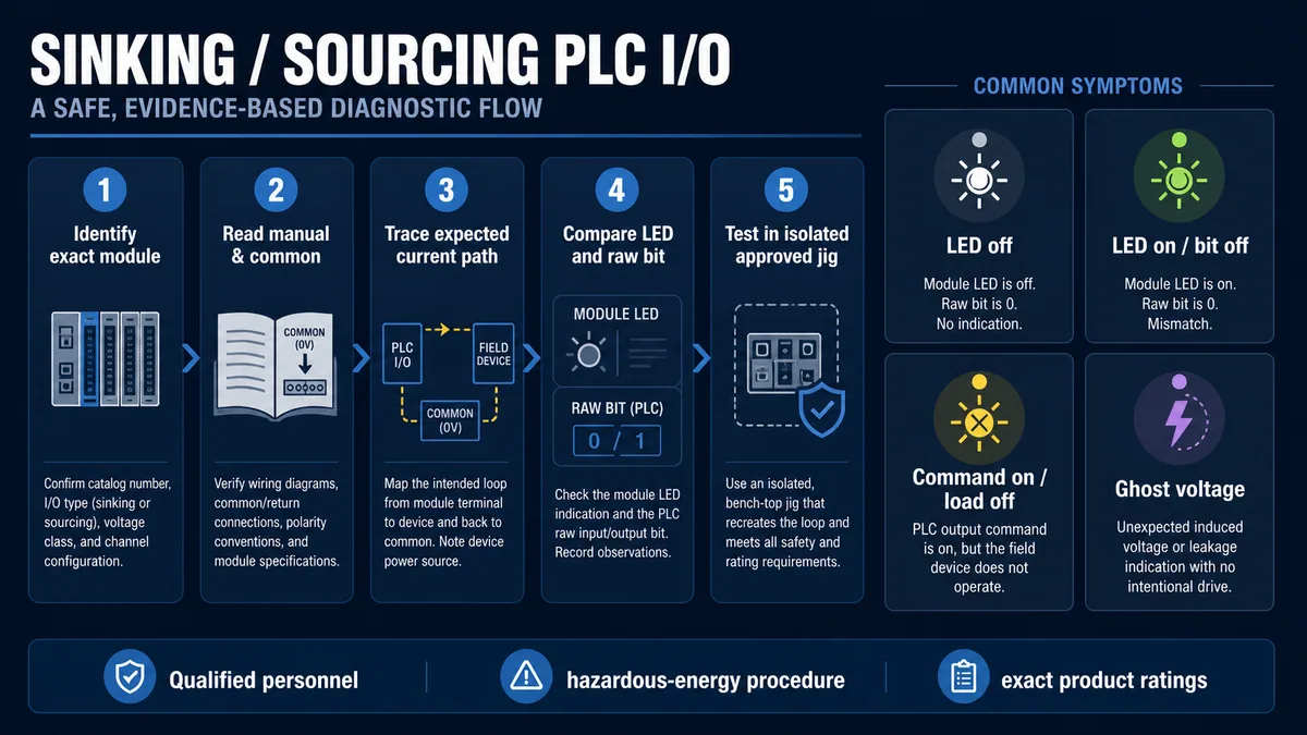
| Gate | Evidence | Stop condition |
|---|---|---|
| exact identity | controller, module/base, channel/group, field device and load catalogue numbers/revisions | any part or drawing cannot be positively identified |
| manual/common | input/output type, common polarity, supplies, isolation, limits and safe procedure | actual connection differs from approved manufacturer/project documentation |
| current path | complete +24 V-to-0 V loop with source, load/input and sink; all fault states | no complete loop or prohibited shared/backfeed path |
| software/indication | channel LED/diagnostic, raw I/O bit, mapped tag, command and application state | force/bypass would be needed to continue outside approved test |
| controlled proof | isolated approved jig/simulator or site-authorized qualified-person test | ratings, energy state, test instrument/category or personnel authorization unclear |
Use the PLC wiring simulator to practise current paths, commons and signal states without touching a field circuit. It does not reproduce the exact leakage, threshold, protection, isolation or hazardous-energy behavior of installed hardware. For the full channel diagnostic chain, see PLC input and output troubleshooting.
Diagnose the symptom, not only the voltage
| Symptom | First discriminating evidence | Likely boundary | Avoid |
|---|---|---|---|
| sensor LED changes, PLC input LED stays off | exact sensor output type versus input/common plus complete loop | PNP/NPN mismatch, open common/signal, sensor supply or threshold | changing PLC logic first |
| input LED on, raw bit off | correct module/channel address, diagnostics/filter and controller state | wrong mapped point, module/bus fault or documentation mismatch | rewiring a proven electrical point |
| raw bit on, application tag off | mapping/alias and logic task/condition | software ownership/filter/interlock | replacing sensor |
| output command/LED on, load off | output group supply/return, diagnostic and load feedback | missing load power, open circuit, overload/protection, wrong output role | declaring PLC output healthy from LED alone |
| output off, meter shows voltage | test instrument impedance, output leakage and rated test load | ghost voltage/coupling rather than usable current | shorting the point or adding arbitrary resistor |
| output turns off under load | channel/group current, inrush, temperature and diagnostic | overload/short/derating or voltage drop | repeated reset without correcting load |
| several adjacent points fail | shared common/potential group and module supply | group wiring/supply/base fault | replacing every field device |
| input flickers | actual signal, filter, common integrity, cable/noise and sensor leakage | marginal threshold, bounce, noise, supply dip or connection | hiding with maximum filter before finding cause |
| load remains faintly energized | off-state leakage, load sensitivity and suppression/interface | solid-state leakage or backfeed | assuming OFF bit means zero current |
| NPN circuit turns on after ground fault | negative-logic current path and fault location | active-low topology consequence | treating the ON state as valid process demand |
Commission every I/O pairing as a contract
Create one controlled record per channel rather than a generic note that “inputs are PNP.” It makes later replacement and fault analysis reproducible.
Digital I/O acceptance matrix
| Gate | Test | Pass evidence |
|---|---|---|
| identity | compare PLC/module/base and field device/load to BOM/manual/drawing | exact products and revisions controlled |
| de-energized circuit | trace approved source, input/load, sink, common, protection and isolation | complete loop with no undocumented bridge/backfeed |
| polarity/role | compare PNP/NPN/contact and sinking/sourcing group/output | complementary source/sink roles on every electronic interface |
| electrical limits | worst supply tolerance, ON/OFF current/voltage, channel/group, inrush, drop, leakage, temperature | calculations remain inside guaranteed regions |
| diagnostics/mapping | actuate controlled field/simulator state and compare device, LED, raw bit and tag | one-to-one state/quality mapping with expected filter time |
| output load | command through approved sequence and compare terminal/load/feedback | correct load state without protection/thermal fault |
| OFF/fault behavior | field signal off, supply/common loss, open/short cases as authorized | defined quality, alarm, application response and no unintended load |
| restart | PLC/module/field supply sequencing under approved process state | no unintended pulse, latched stale command or false input |
| documentation | update loop/channel record, drawing, spare and test result | current recoverable baseline |
Required channel register fields
| Field | Purpose |
|---|---|
| equipment/tag and process meaning | connects electrical point to application consequence |
| module/base/channel/common group | exact PLC hardware boundary |
| input/output technology and polarity | sinking, sourcing, relay, push-pull or special interface |
| field product/output/load type | PNP/NPN/contact/two-wire and actual load category |
| voltage/current/threshold/filter ratings | guaranteed electrical and timing contract |
| supply/return/protection/isolation | complete circuit and fault-current boundary |
| PLC raw and application tags | software mapping and ownership |
| fail/STOP/restart behavior | response to faults and lifecycle transitions |
| drawing/manual/revision and test case | reproducible evidence |
Diagnostic answer map for search and AI-assisted design
| User or AI query | Concise answer | Required qualification |
|---|---|---|
| What is a sinking PLC input? | An input circuit that accepts sourced current and provides the return toward 0 V, commonly used with PNP sensors. | Verify vendor terminology, exact common and thresholds. |
| What is a sourcing PLC input? | An input circuit that supplies current which an NPN field device sinks toward 0 V. | Exact module can be fixed or common/configuration selectable. |
| Does PNP connect to sinking or sourcing input? | PNP sourcing output generally connects to a sinking input. | Voltage, current, leakage, common, isolation and manual must also match. |
| Does NPN connect to sinking or sourcing input? | NPN sinking output generally connects to a sourcing input. | Verify active-low fault behavior and exact product. |
| What is a sourcing PLC output? | A high-side transistor output that supplies positive current to a load returning to 0 V. | Check load supply, drop, leakage, channel/group current and protection. |
| What is a sinking PLC output? | A low-side transistor output that completes a supplied load's path to 0 V. | Check common/return integrity and exact ratings. |
| Is a dry contact PNP or NPN? | Neither; it passively closes an externally powered circuit and can create a sourcing or sinking path by placement. | Contact voltage/current/category and module diagram still control. |
| Why is there voltage on an OFF PLC output? | Solid-state leakage or capacitive coupling can produce ghost voltage on a high-impedance meter. | Compare with the published leakage and an approved rated-load test method. |
| Can PLC transistor outputs drive a contactor directly? | Only if the exact coil steady/inrush/energy and output ratings/protection/suppression permit it. | Often an interposing interface is selected; engineer it rather than assume. |
| Can PNP and NPN sensors share one input bank? | Usually not if the bank has one common polarity; special individually configurable/bidirectional modules can differ. | Verify per-channel versus per-group capability. |
Frequently asked questions
What is the easiest way to remember sinking and sourcing?
Trace conventional current from +24 V to 0 V. The device that supplies current from the positive side is sourcing; the device that completes the return toward 0 V is sinking. One complete loop normally needs one of each.
Is PNP positive and NPN negative?
That shorthand points toward their common industrial behavior but is incomplete. A typical PNP sensor sources positive current; an NPN sensor sinks current to 0 V. Supply polarity, NO/NC state, input common, thresholds and exact terminal functions still require the product diagram.
Why does a PNP sensor need a sinking PLC input?
When the PNP sensor turns on, it supplies current into the input terminal. The sinking input provides the internal path to its 0 V common, completing the loop. Two sourcing sides would not provide the intended return.
Can I change a PLC input from sinking to sourcing?
Only if that exact input group is documented as configurable and its common/wiring/software selection supports the change. Many modules are fixed. Changing a shared common affects every channel in that group and requires controlled rewiring, review and retest.
Are sourcing outputs always PNP transistors?
High-side DC sourcing outputs are commonly implemented with PNP or P-channel/high-side semiconductor stages, but internal technology varies. Use “sourcing/high-side” behavior and the product specification rather than selecting replacement hardware from transistor shorthand alone.
Can a relay output be sinking or sourcing?
An isolated dry relay contact is not inherently either. The external circuit can place the contact on the positive/source side or return/sink side if the contact, load, supply, protection and application ratings permit. Some relay-output commons are grouped, so verify the terminal unit.
Why does my sensor LED turn on but the PLC input does not?
The sensor can detect its target while its output current has no compatible loop to the PLC. Check exact PNP/NPN output, input sinking/sourcing type, group common, supply/return, signal conductor and guaranteed ON current/voltage before software mapping.
Why does an OFF solid-state output show 5 or 24 volts?
A high-impedance meter needs very little current, so off-state leakage, diagnostics or capacitive coupling can charge the point. That does not prove usable load power. Use the exact output leakage specification and an approved test method/rated load; never short the terminal to “prove” it.
Can I mix different 24 VDC supplies on PLC I/O?
Only through an engineered reference/isolation arrangement permitted by every connected module and device. Unplanned commoning can create ground loops, backfeed or destructive fault current; isolated supplies can also leave no signal return. The system drawing must define bonding and isolation.
Does short-circuit protection make a PLC output indestructible?
No. Protection has voltage, current, time, temperature, reset and repetition limits. Repeated faults, load inrush, group overload, feedback or excessive inductive energy can still damage hardware or create unsafe behavior. Clear the cause and follow the exact module recovery procedure.
Sources, review scope, and limitations
This guide was reviewed on August 28, 2026 against current public first-party documentation. Terminology, commons, thresholds, isolation, protection and compatible devices vary by PLC, signal module, base/terminal unit, sensor/load, firmware/configuration and wiring standard. Verify the exact installed combination and retain the tested documentation revision.
- S7-1200 G2 Programmable Logic Controller System Manual — Siemens
- MicroLogix 1000 Programmable Controllers installation instructions — Rockwell Automation
- 1762 DC input/output module installation instructions — Rockwell Automation
- POINT I/O Modules Selection Guide — Rockwell Automation
- Inductive proximity sensor technical data and PNP/NPN diagrams — Rockwell Automation
- Positive and negative logic types — Schneider Electric
- TM3 transistor output electrical characteristics — Schneider Electric
- Configurable positive/ground-switching digital input — Beckhoff
- Digital output leakage and load specifications — Beckhoff
- Output protection for DC inductive loads — Beckhoff
- 29 CFR 1910.147, control of hazardous energy — OSHA
- 29 CFR 1910.333, selection and use of electrical work practices — OSHA
The images show conceptual current roles and decision boundaries; they do not define terminal assignments, conductor colors, wire sizes, protection, grounding/bonding, isolation, supply compatibility, safe test methods or a functional-safety circuit. This page does not authorize energized measurement, terminal work, output forcing, bypassing, grounding changes or live machine testing. Only qualified, authorized personnel following the site risk assessment, electrical safe-work and hazardous-energy procedures, engineered drawings and exact manufacturer documentation should install, modify, measure or test PLC I/O.
Now run it · free · no signup
Wire a 24 VDC sensor to a PLC input
Connect sensor power and signal, present a target and prove the live PLC input changes. Free browser lab — no signup required to finish it.
Ownership disclosure: PLC Programming IO and PLC Simulation Software are operated by the same publisher.
PLC Programming IO Editorial Team
Industrial automation education, references, and software testing
The PLC Programming IO Editorial Team publishes sourced industrial-automation education and documents how material is reviewed, tested, and corrected. A team byline means the publisher is responsible for the page; it does not represent a fictional person or imply an engineering licence.
Coverage:
- • PLC programming concepts and examples
- • Vendor software tutorials and comparisons
- • SCADA, HMI, protocols, and instrumentation
- • Training, careers, and reference material
Review standard:
- • Prefer primary and official sources
- • Record software versions when material
- • Separate tested facts from estimates
- • Publish material corrections
Important scope note
This site provides education, not project-specific engineering approval. Safety, code, and compliance decisions require a qualified person with access to the actual machine and jurisdiction.