PLC Cabinet and Control Panel Wiring: Design, Layout and Troubleshooting
Design, document, wire, inspect and troubleshoot a PLC cabinet or control panel from requirements and fault-current evidence through FAT, commissioning and as-built handover.
Review status: Editorially reviewed against current official OSHA electrical and hazardous-energy rules, the 2024 NFPA 79 public preview, current UL 508A resources, IEC 60204-1:2016+AMD1:2021, IEC 61439-1/-2:2020, current Siemens installation guidance, Rockwell wiring/grounding guidance and Rittal enclosure-climate tooling; applicability, editions, conductor/protection selection, SCCR, clearances, environmental ratings, safety functions, test methods and approval remain jurisdiction-, machine-, circuit-, component- and site-specific
Direct answer
PLC cabinet wiring—also called PLC control-panel wiring or, informally in some regions, PLC panel board wiring—is the engineered connection of incoming supply, isolation and protection, control power, PLC and I/O, safety equipment, networks, relays, drives or starters, terminals, protective bonding and field cables inside an enclosure. A maintainable panel is not created by copying a photograph or following one universal top-to-bottom layout. It is created by carrying requirements and evidence through the complete lifecycle: define the machine and site; identify the governing jurisdiction, standards and approval path; document the one-line and available fault current; select compatible components and establish the panel short-circuit current rating; calculate control-power and heat loads; arrange functional zones around clearances, cable entry, EMC, thermal and service constraints; produce schematics and schedules; build and inspect; perform an approved factory acceptance test; commission safely; and issue verified as-built records.
The physical layout should follow the current path, heat sources, manufacturer mounting rules, electromagnetic compatibility needs, cable entry, bending space, enclosure environmental duty, operator access and future maintenance. Incoming power, power conversion, PLC/I/O, safety, network, motor-control and field-terminal functions normally need deliberate zones, but their exact positions depend on the design. A fixed spacing, wire color, duct-fill percentage or service-loop dimension is not universally valid. Record the project rule and its source instead of turning a local convention into a global requirement.
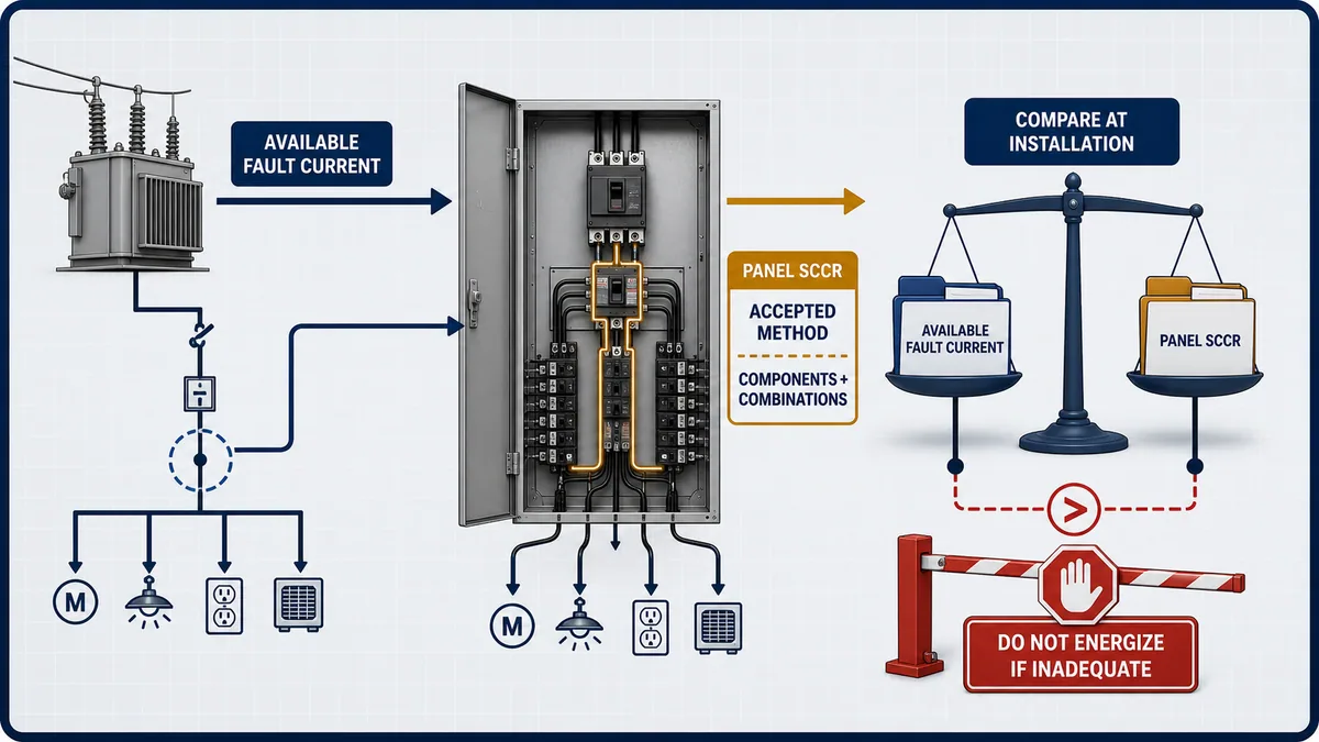
Before energization, compare the available fault current at the installation point with the panel's verified short-circuit current rating (SCCR). Where UL 508A applies, use the current accepted method and component/combination data; do not assume the answer is always the lowest nameplate value because tested combinations and current-limiting arrangements can change the result. Confirm conductor, terminal, protective-device, interrupting, voltage, temperature, environmental and listing/labeling constraints from the exact selected products and adopted rules.
For troubleshooting, trace one documented path at a time: source and protective device, control-power distribution, terminal, field device, PLC channel, program command or state, output interface, load and independent feedback. Compare drawing identity with measured and online evidence. A true input bit does not prove the field device is correct, and an energized output command does not prove current reached the actuator. Stop when the work crosses the approved energized-work, arc-flash, hazardous-energy, safety-function or test-authority boundary.
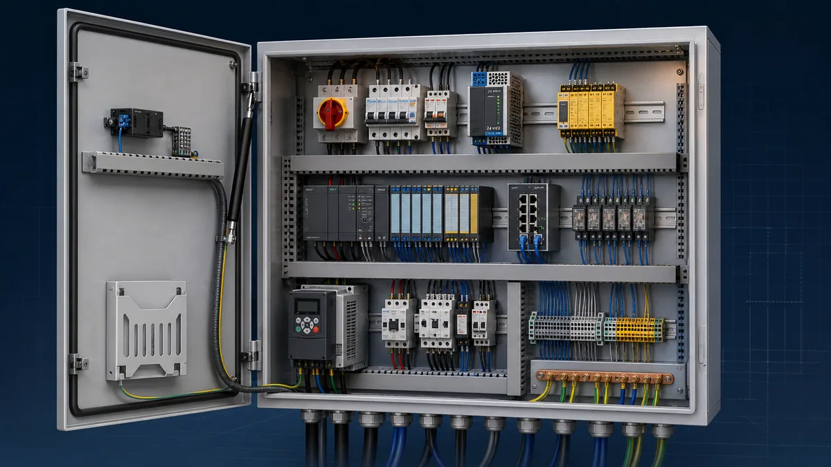
PLC cabinet or control panel: what does the query mean?
In ordinary automation conversations, PLC cabinet, PLC control cabinet, PLC panel and PLC control panel often refer to the same enclosed assembly. The words are not a complete technical classification. A search for “PLC cabinet” may mean the empty enclosure, the mounting-plate layout, the finished industrial control panel, its PLC/I/O wiring or the complete design-and-test lifecycle. Resolve the assembly boundary and applicable product/machine rules before choosing components or copying a diagram.
| Term used in a drawing, quote or search | Plausible scope | Clarification required before design |
|---|---|---|
| PLC cabinet / control cabinet | enclosure plus internal control equipment, or sometimes only the enclosure | empty enclosure or completed assembly; indoor/outdoor/environmental duty; incoming and outgoing interfaces |
| PLC control panel | completed industrial control assembly associated with a machine or process | jurisdiction, machine/assembly category, supply, fault duty and conformity path |
| PLC panel wiring | internal conductors, field terminals and sometimes external I/O/load connections | exact boundary, voltage classes, cable schedule, drawings and responsible installer |
| PLC panel board / control panel board | often an informal regional phrase for the completed PLC control panel, but panelboard can formally mean power-distribution equipment |
whether the requested assembly is an industrial control panel, a distribution panelboard, or a combination requiring separate product/installation rules |
| mounting plate / backplate | mechanical support for rails, duct and components | enclosure fit, clearances, bonding, weight, tooling and service access |
| remote-I/O enclosure | distributed I/O, local power/protection, network and terminals | supply isolation, network topology, environmental duty and field-cable boundary |
| junction box | mainly field termination or marshalling, possibly without PLC CPU | whether active devices, protection, isolation or heat sources are present |
A defensible PLC cabinet design therefore answers more than “where should the PLC go?” It identifies the exact enclosure duty, source and available fault current, isolation and protective devices, control-power demand, component SCCR/interrupting constraints, PLC/I/O and network interfaces, heat losses, EMC classes, protective bonding, field-terminal plan, conductor identities, safety boundary, required drawings, FAT tests and as-built handover. The rest of this guide applies that same evidence workflow whether the project calls the assembly a cabinet or a control panel.
The planned /guides/plc-cabinet-wiring and /guides/plc-panel-board-wiring wordings are consolidated into this canonical because the captured searches serve the same design, wiring and troubleshooting task. Creating separate long pages would split link, click and answer-engine evidence while forcing readers to choose between synonyms.
Do not let the informal phrase erase a formal equipment boundary. In North American product terminology, UL's panelboard application guide identifies UL 67 as the basic standard for panelboards, while UL identifies enclosed industrial control panels under ANSI/UL 508A. In the IEC assembly family, IEC 61439-3:2024 addresses distribution boards intended to be operated by ordinary persons within its scope, while other assembly and machinery parts can govern different equipment. A PLC may be installed near or supplied from a distribution board, and one enclosure may contain coordinated sections, but that does not make every distribution panelboard a PLC control panel or every control panel a panelboard. Classify the actual assembly before applying construction, marking, SCCR, access or conformity rules.
Start with the machine, site and acceptance requirements
Define the panel boundary and operating context
Write a design-basis record before selecting the enclosure. Identify what enters and leaves the panel, where the supply connection begins, which loads are inside or outside, who operates and maintains it, and what other panels or supplies remain energized when its disconnect is open. Record nominal voltage, phases, frequency, earthing arrangement where relevant, available fault-current evidence, control voltages, prospective loads, simultaneous operating states, starting/inrush behavior, regenerative or stored-energy sources, environmental conditions and cable-entry direction.
The machine and site context changes the design. A clean indoor teaching rig is not an outdoor wastewater cabinet. A sealed washdown enclosure with a VFD is not thermally equivalent to a ventilated room panel. A panel serving a coordinated machine is not automatically governed by the same rules as a building distribution assembly. Hazardous locations, mines, marine service, public access, food hygiene, functional safety, fire systems and utility interconnection can add specialized requirements outside this guide.
| Requirement group | Evidence to obtain | Design decision affected | Acceptance record |
|---|---|---|---|
| supply and fault duty | source one-line, transformer/source data, conductor path, current study and installation point | disconnect, protection, interrupting ratings, SCCR and labeling | approved one-line and fault-current basis |
| loads and modes | load list, simultaneous states, inrush, duty and failure response | feeders, branches, control power, grouping and thermal load | load schedule and design calculation |
| environment | ambient range, solar exposure, dust, water, chemicals, altitude, vibration and condensation | enclosure type, materials, sealing, climate control and derating | environmental specification |
| interfaces | I/O list, networks, remote supplies, field cable types and external energy | terminals, isolation, segregation, shielding, warnings and disconnect scope | interface and terminal schedule |
| people and maintenance | operator actions, access, service frequency, replacement needs and competence | working space, door devices, test points, labels, lighting and spares | maintainability review |
| safety and approval | risk assessment, AHJ, adopted codes/standards, customer spec, NRTL/certification path | safety architecture, component acceptance, construction, marking and verification | compliance matrix and sign-off route |
Separate functional safety from ordinary control
A standard PLC, ordinary output and well-written ladder rung do not create a safety function. The machinery risk assessment defines hazards and required risk reduction. The selected safety-related control system then needs the appropriate architecture, certified components, diagnostics, response time, validation and lifecycle controls. Keep safety-device identities, reset behavior, feedback, discrepancy detection and proof-test requirements explicit in the drawings and validation plan.
Emergency stop, guard interlocking, safe speed, safe torque off and other safety functions cannot be accepted through a generic panel checklist. They need competent safety engineering under the applicable machinery and functional-safety framework. Ordinary control may request a stop and display status, but it must not silently bypass or replace the validated safety path.
Choose the jurisdiction, standards and approval path
Build an applicability matrix instead of naming one universal code
The question is not “Is this a UL panel or an IEC panel?” The question is: what country and local jurisdiction apply; what installation and machine category is involved; which editions have been adopted; what the authority having jurisdiction, purchaser and insurer require; what product certification or listing path is contracted; and which manufacturer instructions form part of the accepted installation.
OSHA 1910.303 requires electrical equipment to be acceptable for the installation, evaluates factors including heating, arcing, interrupting rating and use, and requires listed or labeled equipment to be installed according to its instructions. It also addresses marking and safe access/working space. That does not mean every panel in every country has the same listing route. OSHA's NRTL program FAQ explains the role of nationally recognized testing laboratories in the US occupational context.
For industrial machinery in relevant North American projects, the public NFPA 79 2024 preview shows the breadth of the machinery electrical-equipment lifecycle: disconnecting, grounding and bonding, control circuits, equipment location and mounting, conductors and wiring practices, marking, documentation, testing and verification. UL 508A can be the applicable industrial-control-panel construction and certification framework, but do not state that a UL label is universally required for every US or Canadian panel. Resolve the adopted code, AHJ, end-use and contract.
For applicable machinery, IEC 60204-1:2016+AMD1:2021 covers electrical, electronic and programmable electronic equipment from the supply connection to the machine's electrical equipment. Applicable low-voltage assembly work may involve IEC 61439-1:2020 together with the relevant product part; IEC 61439-2:2020 gives specific requirements for power switchgear and controlgear assemblies within its scope. These are not interchangeable labels, and local adoption and conformity routes still control.
| Question | Why it matters | Record before design release |
|---|---|---|
| Where will the panel be built, installed and operated? | country, state/province and local authority can change adopted rules | jurisdiction and AHJ/contact |
| Is it machinery, process equipment, a distribution assembly or another category? | scope boundaries and product standards differ | equipment classification and rationale |
| Which editions and amendments are adopted or contracted? | “latest” and “adopted” may not be the same | edition-controlled standards list |
| Is listing, certification, field evaluation or declaration required? | component selection, construction and evidence path change | conformity route and responsible party |
| Which customer and insurer requirements are additional? | site practices can be stricter than baseline rules | deviations and acceptance owner |
| Who has design, build, test and energization authority? | prevents an informal review from becoming approval | named roles and hold points |
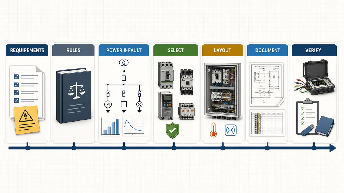
Build the one-line, load architecture and isolation concept
Follow every source and energy path
The one-line should show the supply source, nominal characteristics, isolation, protective devices, transformers or power supplies, major branches and loads, protective-earth/bonding arrangement and interfaces to other equipment. Identify auxiliary and foreign supplies, UPS-backed circuits, regenerated energy, stored energy and conductors that can remain live with the main disconnect open. A door-mounted disconnect handle is not evidence that every internal conductor is de-energized.
Separate the power circuit, control-power distribution, I/O field supplies and external interfaces logically. Decide where faults should be isolated and what operational consequence each protective device creates. One large 24 VDC branch may be simple but can turn one sensor short into a whole-machine outage. Too many undocumented branches create the opposite problem. Segment according to consequence, conductor and device protection, diagnostics, service access and the adopted rules.
Coordinate devices with conductors and loads
Select conductors, terminals, disconnects and protective devices as a system. Check voltage and current, load category, continuous duty, inrush, ambient and grouping, terminal temperature ratings, short-circuit withstand, interrupting rating, conductor material and permitted terminations, motor requirements where present, downstream protection and manufacturer conditions of use. A breaker handle current alone does not prove conductor protection, branch acceptance, selectivity or load compatibility.
| Design artifact | Minimum useful content | Failure it prevents |
|---|---|---|
| source one-line | source, isolation, protection, branches, major loads, PE/bonding and external feeds | hidden energy and undocumented fault path |
| load schedule | load identity, voltage, current, inrush, duty, simultaneity, heat loss and source | undersized supplies and incorrect diversity |
| protective-device schedule | exact device, setting/rating, interrupting/SCCR data, protected conductor/load and coordination evidence | accidental substitution and weak fault path |
| control-power tree | supply, branch protection, distribution terminals, commons/groups and diagnostic point | one unexplained 24 VDC outage |
| isolation matrix | isolator versus energy removed, energy retained and verification point | assuming “main off” means everything safe |
| cable schedule | cable/core, origin, destination, type, shielding/bonding, gland and terminal | field termination ambiguity |
Prove fault-current suitability and panel SCCR
Keep available fault current and panel SCCR distinct
Available fault current is an installation characteristic at a defined point under defined source and conductor conditions. The panel SCCR is the assembly rating established under an applicable method. The installation must not expose the panel to a prospective fault duty beyond the panel's verified capability. Also verify that devices intended to interrupt faults have sufficient interrupting ratings for their application; SCCR and interrupting rating are related design evidence, not interchangeable labels.
Obtain the facility fault-current study or other approved evidence for the actual point of installation. Record its date, assumptions, operating configuration and responsible engineer. A utility transformer value alone is not the final point-of-installation result because upstream and downstream impedance and possible source configurations matter. Recheck after source, transformer, conductor or distribution changes.
Use the accepted component and combination method
Where UL 508A applies, use the current controlled standard and training/engineering process available to the responsible panel shop or designer. UL's official SCCR resource and combination motor controller explanation describe Supplement SB as an accepted determination method. UL also explains that tested combinations can achieve a rating higher than the lowest individual component rating. That is why “the lowest component always sets the panel SCCR” is an unsafe shortcut.
Check the exact component identity, category, conditions of acceptability, branch arrangement, overcurrent device, line/load location, current-limiting conditions and combination-table data. UL's current Supplement SA component resource supports component selection but is not a substitute for the complete controlled evaluation. Preserve the calculation and component evidence with the project record so a later substitution can be reviewed.
| SCCR evidence item | Question to answer | Red flag |
|---|---|---|
| installation fault-current value | What maximum prospective value applies at this panel connection? | value copied from a different bus or old study |
| panel evaluation method | Which adopted/accepted method and edition established the assembly rating? | informal “lowest breaker” note |
| component identity | Are exact catalog numbers, ratings and conditions recorded? | “equivalent component” without review |
| combinations/current limitation | Are upstream/downstream positions and permitted combinations preserved? | rating claimed from an unrelated combination |
| interrupting ratings | Can protective devices interrupt the fault duty where applied? | confusing device SCCR with interrupting rating |
| marking and file | Does the nameplate and technical file match the verified assembly? | label updated without calculation or vice versa |
Live mini-lab
Try it: press START, then STOP
A stop-dominant seal-in rung: START latches the motor output through its own contact, and STOP breaks the circuit.
Watch the output lamp: it stays on after START until you press STOP.
Free to start · runs in your browserOpens plcsimulationsoftware.com — same team
Calculate the 24 VDC control-power demand
Sum credible simultaneous loads, not only nameplate maxima
Create a control-power budget by source and branch. For every PLC, I/O group, HMI, switch, radio, relay, solenoid, sensor and interface, record steady demand, startup/inrush, duty, worst credible simultaneous state, environmental derating and data source. Keep PLC/backplane or electronics power separate from field/load power when the architecture separates them. Include externally powered devices only on the source that actually supplies them.
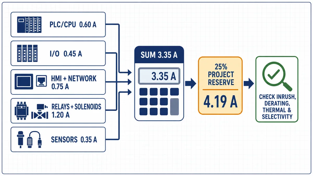
Consider one explicit example using assumed steady currents:
| Assumed 24 VDC load | Simultaneous current |
|---|---|
| PLC/CPU and controller electronics | 0.60 A |
| local and remote I/O contribution on this source | 0.45 A |
| HMI and network equipment | 0.75 A |
| simultaneous relay and solenoid coils | 1.20 A |
| sensors and field interfaces | 0.35 A |
| steady simultaneous sum | 3.35 A |
| with a project-specific 25% steady reserve | 4.1875 A |
The arithmetic is 0.60 + 0.45 + 0.75 + 1.20 + 0.35 = 3.35 A, then 3.35 × 1.25 = 4.1875 A, commonly displayed as 4.19 A for this planning example. These values are not typical equipment ratings, and 25% is not a universal rule. It is an explicit project assumption.
Do not turn 4.19 A into an automatic 5 A selection
A nominal 5 A candidate may still be unsuitable. Verify input supply range, permitted mounting and clearances, ambient/altitude derating, conversion efficiency and heat, startup/inrush and ride-through, dynamic load response, short-circuit behavior, branch coordination, redundancy policy, output adjustment and tolerance, conductor and terminal limits, diagnostics and the consequence of failure. Confirm whether capacitive loads, DC-DC converters, electronic circuit protectors or simultaneously switching coils create a transient beyond the steady budget.
Use exact manufacturer curves and conditions. If a redundant supply architecture is required, define whether each source carries the full worst-case load and how decoupling, monitoring and common-cause failures are handled. A second power supply in the enclosure is not redundancy if both depend on the same unprotected upstream point or share an undocumented failure path.
Arrange functional zones around real constraints
Reject the universal top-to-bottom panel recipe
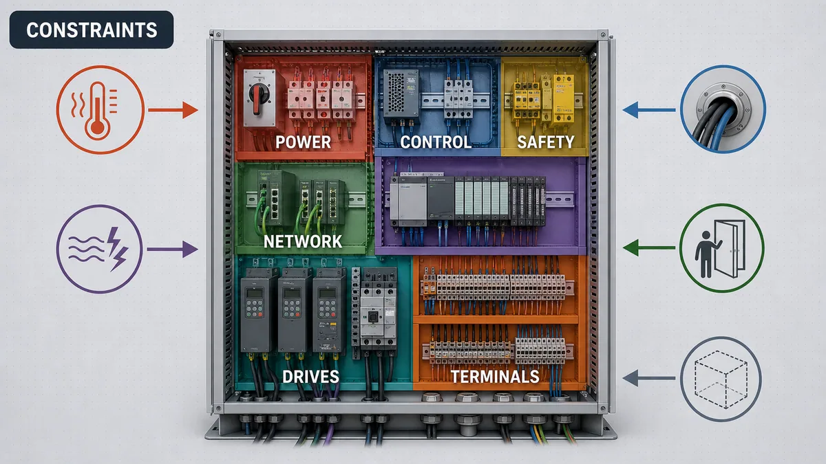
There is no single standard arrangement that places all incoming power at the top, PLCs in the middle and terminals at the bottom. Cable entry may be top, bottom or side. A disconnect mechanism may constrain the door and mounting plate. VFD cable routing, heat flow, touch safety, bending space, short-circuit path, device clearances, door swing, service access, enclosure strength and expansion can change every position. Manufacturer instructions may require a specific orientation or empty space around a device.
Use functional zones as a planning tool: incoming isolation/protection; power distribution and conversion; PLC/I/O; safety; industrial network; relays and interfaces; drives/starters; terminals and cable entry; protective-earth/bonding; and climate-control equipment. Place each zone by interactions and constraints, then trace every conductor route. Review the layout with an electrician or panel builder before drilling the mounting plate.
Design for installation and replacement
Show the enclosure, mounting plate, door equipment, cable entries, wire duct, DIN rail, glands/conduit, bonding points and service envelopes to scale. Import exact device dimensions and clearance envelopes where possible. Check whether a screwdriver, torque tool, test probe or module-removal motion can reach the component after wire duct and adjacent equipment are installed. Allow door wiring to move through its full range without abrasion or loading terminals.
Siemens' current S7-1500/ET 200MP system manual, for example, gives exact cabinet clearances and installation rules for that product family. Those numbers belong to that equipment and revision; they are not generic PLC clearances. Repeat this exact-manual check for the power supply, switch, safety equipment, relays, drive, terminals and enclosure accessories.
| Layout constraint | Evidence | Review question |
|---|---|---|
| manufacturer clearance/orientation | exact manual and device drawing | Can heat dissipate and can the device be installed/removed as specified? |
| cable entry and bend | cable schedule, gland/conduit plan and cable data | Can every cable reach without violating bend, strain or sealing requirements? |
| power and EMC route | one-line, drive/manual EMC instructions and cable classification | Are noisy and sensitive routes controlled for their actual circuit types? |
| service access | maintenance task analysis and tool envelopes | Can a terminal, fuse, module or fan be reached and replaced safely? |
| door and enclosure mechanics | enclosure data, door devices and wiring motion | Are weight, support, bonding, flex and closing clearances acceptable? |
| expansion | approved future I/O/load assumptions | Are documented spare terminals, rails, duct and heat capacity genuinely usable? |
Control heat, ambient conditions and enclosure climate
Build a heat-loss inventory from exact component data
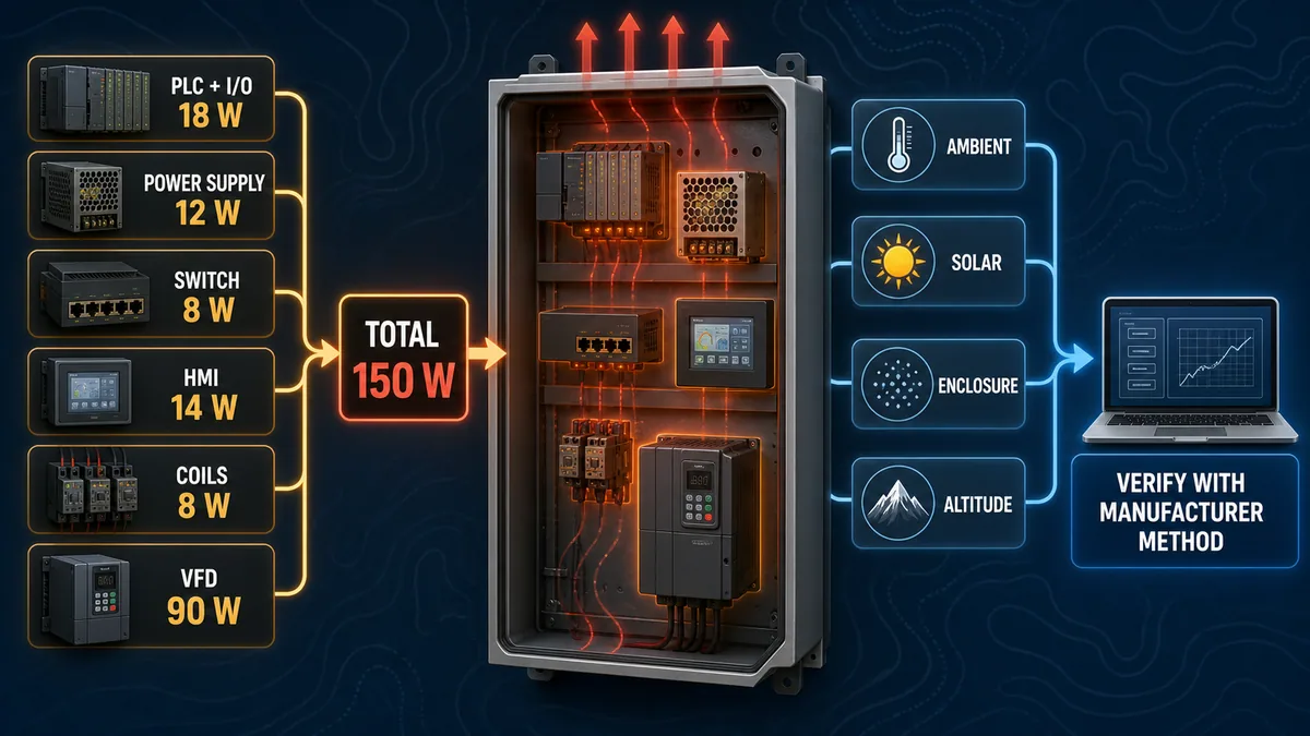
Heat inside the enclosure is not the sum of load power. Use manufacturer power-loss or dissipation data under the actual operating point and conditions. Separate internal loss from power delivered to an external load. Include power supplies, PLC/I/O, network equipment, HMIs, relays and contactors, transformers, electronic protection, drives, braking components and any enclosure accessories that reject heat inside.
For one worked inventory, assume exact project documents give: PLC and I/O 18 W; 24 VDC power-supply loss 12 W; switch 8 W; HMI 14 W; interface coils 8 W; VFD loss 90 W. The estimated internal heat load is 18 + 12 + 8 + 14 + 8 + 90 = 150 W. That only establishes one input to the thermal design.
Model the environment and verify the selected solution
The acceptable internal temperature depends on the limiting component, ambient range, enclosure material and surface area, mounting, solar exposure, sealed versus ventilated construction, dust/water/chemical duty, altitude, neighboring heat sources, air circulation, filter condition, humidity and condensation, component derating and lifecycle. Fans do not cool below ambient; filters load with contamination; an air conditioner introduces condensate and maintenance; an enclosure heater may be necessary to prevent condensation even when the operating concern is heat.
Use the enclosure/climate-control manufacturer's verified method and document inputs. Rittal describes RiTherm as an enclosure climate-control planning tool that calculates needs and recommends suitable systems. Other enclosure vendors provide their own tools and data. The point is the evidence workflow, not one vendor. Validate the final arrangement against all equipment manuals and the applicable assembly verification process.
| Thermal input | Example evidence | Frequent mistake |
|---|---|---|
| component losses | exact data sheet at operating point and switching/load state | using load power as internal heat |
| worst credible simultaneity | machine operating-mode study | summing impossible maxima or ignoring real overlap |
| ambient and solar | site specification and measured/design extremes | using room average for an outdoor cabinet |
| enclosure construction | dimensions, material, mounting, sealing and surface exposure | assuming all surfaces dissipate equally |
| airflow and contamination | fan/filter curve, pressure, dust loading and maintenance interval | accepting a clean-filter calculation forever |
| temperature limits/derating | exact device manuals and altitude/ambient curves | checking only the PLC rating |
| verification | manufacturer calculation, temperature test or approved validation | selecting cooling from watt total alone |
Engineer EMC, protective bonding and signal reference
Classify circuits before routing conductors
Do not route solely by nominal voltage. A 24 VDC solenoid or relay-coil circuit can be noisy, while a 24 VDC analog or encoder circuit can be sensitive. Classify incoming and motor power, drive input/output and braking paths, switched inductive loads, ordinary digital control, analog/instrumentation, high-speed encoder and communication circuits. Apply exact device, cable and system guidance for separation, crossing, shielding, bonding and termination.
Rockwell's Industrial Automation Wiring and Grounding Guidelines, publication 1770-4.1, explains raceway layout, mounting/bonding/grounding, power distribution and surge-suppression principles for the systems in its scope while explicitly saying local electrical codes take precedence. Use it as product-family guidance, not as a universal distance table. Drive, encoder, analog module and network manuals can be more specific.
Never publish “keep signal wiring six inches from power” as a global law. The required physical separation or barrier depends on circuit classification, insulation, product instructions, applicable rules and installation geometry. When routes must intersect, an approximately perpendicular crossing can reduce parallel coupling, but it does not fix incompatible insulation, unsafe segregation or incorrect shielding.
Distinguish protective earth from functional reference
Protective earthing and bonding provide a safety path and keep exposed conductive parts within the designed protection system. A functional signal reference, shield termination, equipotential/high-frequency bond or 0 V reference serves a different electrical purpose. They may be connected at defined points under the design, but the names are not interchangeable and a green/yellow protective conductor must not become a convenient signal conductor.
Bond doors, mounting plates, gland plates, enclosure sections and equipment as required by the approved design and product instructions. Remove insulating finishes only by an accepted bonding method; use suitable hardware and protect the joint from corrosion. Verify continuity using the prescribed test method and acceptance limit, then record the result. Do not infer a valid bond from a hinge or mounting screw.
Design terminals, conductor identification and wire management
Make every field connection traceable
The terminal plan is the interface contract between panel and field. Give each terminal a stable designation that maps to schematic, cable/core, I/O or device, signal name, voltage/circuit class, source, destination, shield/bond treatment and test-disconnect or fused function where present. Group for safe construction and maintenance, not merely for visual symmetry.
Use disconnect, fused, multi-level, sensor/actuator, PE or shield terminals only within their exact ratings and conditions. Check conductor type and range, ferrule compatibility, number of conductors per clamping point, current/voltage, short-circuit and temperature ratings, jumper capacity, test accessories and marking. “One wire per screw” is not a universal terminal law; the manufacturer defines permitted conductor combinations. Likewise, ferrules are not universally required or universally allowed. Follow the selected terminal and adopted rules.
Treat color and duct fill as documented project rules
Conductor colors vary by jurisdiction, circuit function, customer and retained/foreign-voltage convention. Protective-conductor colors have special restrictions in many systems. Never guess identity from color; verify the drawing, label and electrical state. Document the color convention, its authority and how external or retained energy is marked.
Wire duct must accommodate the actual conductor count, sizes, insulation, bends, heat/grouping considerations, covers and future capacity under its manufacturer data and project rules. This guide does not impose a universal 50% maximum or 20–30% spare value. If a project chooses a planning fill threshold, label it as a project assumption and verify the final installation against applicable code, standard, conductor derating and duct manufacturer limits.
| Terminal/wire record | Required identity | Diagnostic value |
|---|---|---|
| terminal designation | strip, position, level and function | moves directly from drawing to physical point |
| source/destination | device, pin/channel and cable/core | prevents same-color/same-number ambiguity |
| circuit class | voltage, source, retained/foreign energy and EMC class | controls routing and safe isolation |
| conductor detail | material, size, insulation, color, ferrule/lug and termination data | supports inspection and replacement |
| protection/disconnect | fuse/electronic protection/test-disconnect identity | isolates one fault path without improvisation |
| shield/bond | cable shield end treatment and bonding point | prevents random field changes |
| spare status | unused, reserved or fitted spare and approved capacity | distinguishes real expansion from empty-looking space |
Produce drawings that can build and troubleshoot the panel
Keep one stable identity across every document
Device tags, terminal numbers, wire numbers, cable/core IDs, I/O addresses/tags and physical labels must agree. Use cross-references so a technician can move from one-line to branch schematic, terminal plan, I/O list, device location, cable schedule and PLC tag without interpreting a private naming habit. Revision-control the whole set; a correct PDF with an outdated terminal export is not an as-built package.
At minimum, the project may need a design basis and compliance matrix, one-line, power and control schematics, safety drawings, panel layout, terminal and cable schedules, bill of materials, device settings, I/O list, network architecture/address plan, label schedule, heat and power calculations, SCCR/fault-current records, FAT/SAT procedures, inspection/test records, backups and revision history. The exact deliverables depend on scope.
Make assumptions and limitations visible
Put units, data sources, calculation assumptions and hold points beside the design evidence. If the available fault current is pending, do not bury it in an email. If a drive heat loss is estimated for preliminary layout, mark it for replacement with exact data before release. If a field cable is supplied by another party, identify the interface owner. If a safety function is excluded from the ordinary panel FAT, point to its separate validation plan.
| Document | Design use | FAT/commissioning use | Maintenance use |
|---|---|---|---|
| one-line and isolation matrix | define source, protection and energy boundary | verify sources, isolation and retained energy | diagnose whole-panel or branch loss |
| schematic and cross-reference | define circuit behavior and connections | point-to-point and functional test | trace command, supply and feedback |
| layout and device list | build clearances, zones and exact hardware | physical inspection | locate and replace components |
| terminal/cable schedule | define field interface | loop/identity checks | isolate field versus panel fault |
| I/O list and tag map | define channel, signal and behavior | I/O checkout | compare field, channel and program identity |
| settings/calculations | establish protection, supply, thermal and SCCR basis | verify programmed/adjusted values | control substitutions and changes |
| as-built and backup | capture accepted configuration | handover baseline | restore after failure or modification |
Build, inspect and test before field energization
Use controlled construction and independent inspection
Build from released drawings and exact bill of materials. Record substitutions before installation because a “same size” breaker, terminal, power supply or drive can change approvals, SCCR, heat, terminal conditions, diagnostics and spare parts. Apply manufacturer torque and assembly instructions with calibrated tools where required, and record critical settings and results rather than painting a generic torque mark as proof.
Perform the appropriate de-energized inspections: component identity and mounting; clearances and barriers; conductor identity and termination; door wiring motion; protective bonding; cable entry and strain relief; retained-energy warnings; labels/nameplate; enclosure sealing; duct covers; foreign material; documentation agreement. Electrical tests and acceptance limits must come from the governing procedure and equipment rules. Insulation-resistance or dielectric testing can damage connected electronics if applied without a suitable isolation plan.
Control the first energization and functional test
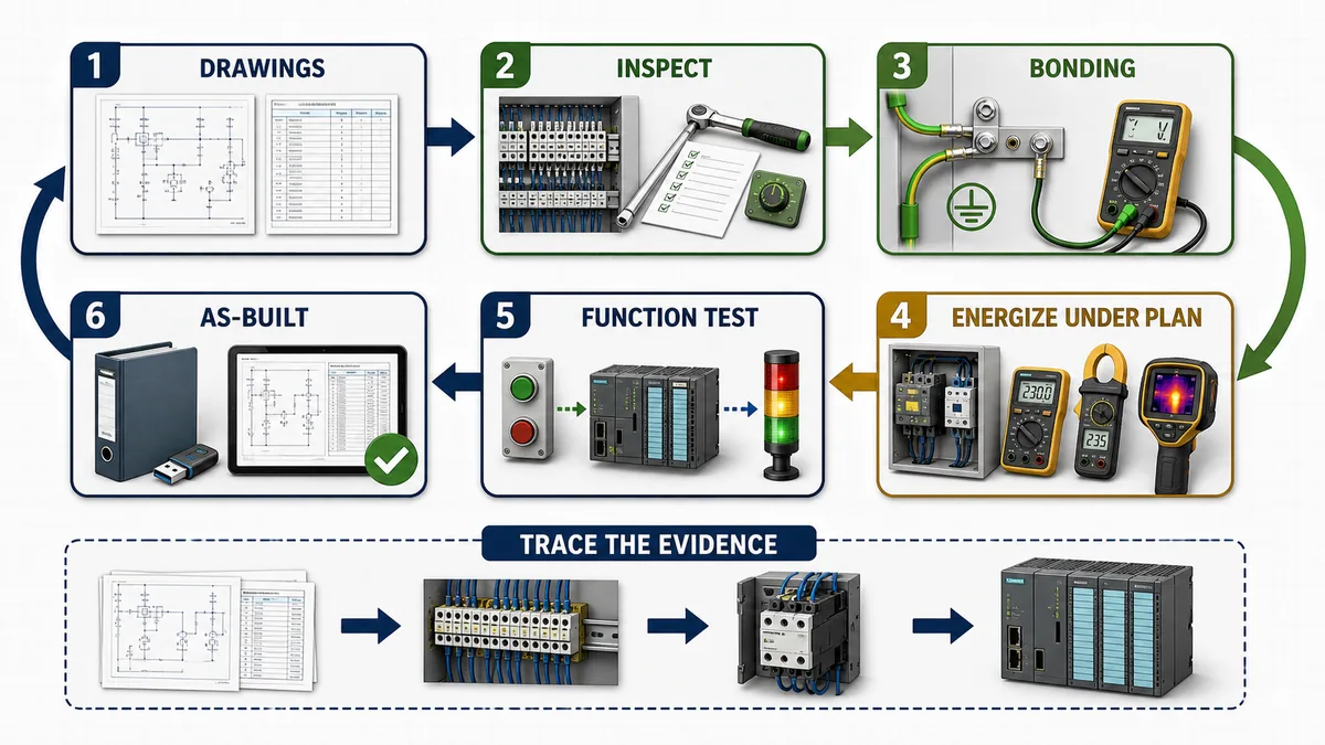
Create an energization plan with authority, prerequisites, boundaries, expected readings, protective equipment, test instruments, stop criteria and recovery. In the US workplace context, OSHA 1910.333 addresses selection and use of work practices for electrical safety, while OSHA 1910.147 addresses control of hazardous energy. Follow the site electrical-safety and lockout/tagout programs; this article is not an energized-work procedure.
Stage the test so evidence narrows risk: verify isolation and protective bonding under the approved procedure; confirm source and protective-device configuration; energize controlled branches; check control-power voltages, current and diagnostics; load software and configuration from controlled files; verify network identity; test each I/O point end-to-end; test commands, permissives, interlocks and independent feedback; exercise normal, abnormal and power-recovery states; observe thermal behavior at representative load; close punch items; and issue signed records.
Commission and troubleshoot from documented boundaries
Prove source, field, controller and load separately
When the panel does not behave, start with the symptom and exact operating mode. Check active alarms, first-out reason, recent changes, drawings and safe work boundary. Then divide the path into evidence layers. For a missing input: prove the field condition independently; identify the terminal and supply/common; inspect channel diagnostics and raw/status data; verify mapping and tag ownership; then inspect logic use. For a failed output: confirm the command owner and permissives; module/channel state and field power; protection and terminal path; interface/load; and independent actuator feedback.
Do not use a force as the first diagnostic action. A force can bypass the logic evidence you need, create a dangerous output, survive longer than intended or hide an intermittent fault. If an approved test requires forcing, record authorization, target, expected effect, interlocks/safety boundaries, observation and removal verification. Prefer simulation and offline review when testing can be separated from real energy.
Diagnose whole-panel and intermittent symptoms systematically
| Symptom | First evidence | Discriminating checks | Do not conclude yet |
|---|---|---|---|
| entire panel appears dead | source/disconnect indication, upstream status and one-line | approved absence/presence-of-voltage checks, main protection and retained supplies | dark HMI means no incoming power |
| PLC runs but field I/O is absent | module/group diagnostics and field-supply status | branch protection, commons, terminal voltage under safe procedure and channel status | CPU health proves field power |
| fuse/protector trips repeatedly | exact branch, timing and load state | conductor/load fault, inrush, suppression, device rating and downstream isolation | install a larger device |
| analog value jumps with drive operation | raw value/quality synchronized with drive state | routing, shielding/bonding, reference, field power and module diagnostics | “bad PLC card” from correlation alone |
| network faults appear under load | switch/device diagnostics and timestamps | power quality, bonding/EMC, link counters, topology and traffic/configuration | cable replacement is always the fix |
| output bit is true but actuator is still | command, output status, field power and independent feedback | protection, terminal path, interface, coil/load and mechanical/process condition | output bit proves current or motion |
| random resets or warm failures | event log, supply trace, temperature and load correlation | control-power transient, heat, loose connection, grounding/EMC and firmware/config | intermittent means software |
Keep a time-aligned evidence log: symptom, operating mode, command/request, permissive or state, input/output values with quality, module and network diagnostics, control-power observations, temperature, protective-device state and recent intervention. Intermittent faults become tractable when evidence is correlated instead of collected from memory.
Common design and build failures to prevent
A tidy panel can still be electrically wrong
Visual neatness helps maintenance but does not prove protection, SCCR, thermal performance, EMC, terminal suitability or documentation accuracy. Common failures include an unverified source/fault-current basis; exact devices replaced with “equivalents”; external or retained supplies omitted; control-power branches without consequence planning; drive output routed beside sensitive analog circuits contrary to instructions; shield and protective earth confused; door bond assumed through hinges; unusable spare space; inaccessible terminal screws; heat estimates that count nameplate load instead of internal loss; and drawings released before terminal and field changes are captured.
Another failure is over-generalized rules: always top-to-bottom, always 150 mm separation, always 50% duct fill, always one conductor per terminal, always ferrules, always a specific color. Any of those may be a valid local or manufacturer requirement in a defined context. None should be published as universally applicable without the source and scope.
Preserve modification control after handover
A panel can lose its verified state through a small maintenance change. A substituted protective device may change SCCR or coordination. Added I/O and relays may overload control power or create heat. A new cable can defeat segregation or sealing. A replaced drive may require new clearances, filters, cable rules or settings. Route changes through documented engineering review, update the affected calculations and drawings, repeat appropriate tests, then reissue the as-built baseline.
For networked panels, protect configuration and remote access as part of the lifecycle. NIST's Guide to Operational Technology Security, SP 800-82 Rev. 3 emphasizes OT's performance, reliability and safety constraints. Record asset identity, network boundaries, approved services, configuration backups and change responsibility. Cybersecurity does not replace electrical engineering, and electrical isolation does not prove cyber isolation.
Diagnostic answer map for panel design and wiring questions
If someone asks how to lay out a PLC control panel
Answer with a constraint process, not a picture to copy. Establish enclosure/environment and cable entry; place disconnect and energy-path components under their mechanisms and instructions; reserve exact clearances; isolate heat and EMC interactions; make terminals and service points reachable; model wire routes and bends; verify door movement and bonding; calculate heat; review the scaled layout; then release drawings. State that functional zones are useful but positions are project-specific.
If someone asks how to size the 24 VDC power supply
Ask for the exact load list, source boundaries, simultaneous states, inrush/startup, ambient/altitude, redundancy, failure consequence and manufacturer derating. Sum credible steady demand, state any project reserve, then test the candidate against dynamics, protection, thermal and terminal constraints. A watt or amp sum alone is not selection evidence.
If someone asks whether a panel needs UL 508A
Ask for country, jurisdiction, equipment category, AHJ, adopted code, customer/insurer specification and contracted certification route. Explain that UL 508A is a major North American industrial-control-panel framework, but do not claim every panel in the US or Canada universally requires a UL 508A label. The responsible local authority and project requirements decide applicability.
If someone asks how to troubleshoot a dead PLC panel
Use the one-line and isolation matrix to identify every source, including retained or external supplies. Under the approved safe-work procedure, establish whether the fault is upstream supply, isolation, main/branch protection, control-power conversion, distribution or the PLC itself. Use device diagnostics and measured evidence at documented boundaries. Do not infer the source from LEDs alone or bypass protection.
If someone asks why an output is on but the motor or valve does not move
Separate program command, module-reported state, field power, protective device, terminal path, interface or contactor, load electrical condition, actuator mechanical condition and process permissive. Check independent feedback. An output image or echo does not prove field current or physical motion. Use the PLC inputs and outputs guide for point design and the PLC I/O troubleshooting guide for an ordered field-to-logic method.
Frequently asked questions
Is a PLC panel board the same as a PLC control panel?
People often use “PLC panel board” informally to mean a PLC control panel, especially when searching for an internal wiring diagram. It is not a safe formal equivalence. Panelboard can mean a power-distribution product with buses and overcurrent devices, while an industrial control panel contains power and/or control components for controlling equipment. Define the assembly, jurisdiction and conformity path first; use the controlled drawing and applicable product/machine rules rather than the search phrase.
Is a PLC cabinet the same as a PLC control panel?
Often, but not automatically. Teams commonly use PLC cabinet, control cabinet, PLC panel and control panel for the same enclosed control assembly. A supplier may also use “cabinet” for the empty enclosure or mechanical build. Define whether the scope includes enclosure, mounting plate, incoming supply, protection, PLC/I/O, safety, networks, terminals, field cables, testing and certification before comparing designs or quotes.
What is the best layout for a PLC control panel?
There is no universal best physical order. Use functional zones, then place them around incoming/current paths, cable entry, manufacturer clearances, heat, EMC, touch safety, service access, enclosure mechanics and future documented capacity. Verify the scaled layout with exact device and cable data before fabrication.
Is UL 508A required for every PLC panel in the United States or Canada?
No universal statement is safe. Requirements depend on jurisdiction, equipment type, adopted codes, AHJ, customer or insurer terms and the listing/certification route. UL 508A is an important North American industrial-control-panel standard, but the responsible project parties must determine whether and how it applies.
Is panel SCCR always the rating of the lowest-rated component?
No. Under an applicable accepted method, individual component ratings matter, but listed/tested combinations and permitted current-limiting arrangements can change the established panel rating. Use the current method, exact component/combination data and documented circuit arrangement; never select SCCR from a casual lowest-label shortcut.
How do I calculate the 24 VDC PLC panel power supply size?
List every load on that source, its exact steady current, inrush/startup, duty and worst credible simultaneous state. Sum the demand, state any project-specific reserve, then evaluate candidate supplies for input range, derating, dynamics, protection, heat, terminals, redundancy and failure behavior. The arithmetic is a planning input, not the final selection.
How much space should be left between power and signal wiring?
There is no single universal distance. Classify the actual circuits, then follow the governing rules and exact device, cable, drive, I/O and network instructions for separation, barriers, insulation, crossings, shielding and bonding. Do not treat all 24 VDC circuits as sensitive signals or one internet distance as code.
Should every stranded wire use a ferrule?
Not automatically. Use the selected terminal or device manufacturer's permitted conductor preparation and the applicable project rules. A correct ferrule can improve a compatible termination, while an incorrect size, crimp or use in a terminal not approved for it can create a poor connection.
What wire-duct fill percentage should a PLC panel use?
Use the applicable rule, duct manufacturer data, conductor grouping/heat constraints and a documented project planning allowance. This guide does not impose a universal 50% maximum or spare percentage. Verify the final build rather than relying on a preliminary visual estimate.
What documents should be delivered with a PLC control panel?
Typical evidence includes design basis, applicability/compliance matrix, one-line, schematics, layout, bill of materials, terminal and cable schedules, I/O list, network architecture, settings, load/thermal/SCCR records, inspection and FAT/SAT results, software/configuration backups, punch-list closure and revision-controlled as-built files. Contract scope determines the final set.
How should a PLC control panel be tested before commissioning?
Use a competent, approved procedure with defined authority and safety boundaries. Inspect identity, mounting, terminations, labels, bonding, clearances and enclosure integrity; perform applicable electrical tests without damaging electronics; control first energization; verify power and diagnostics; test every I/O point and function; observe representative thermal behavior; and record results plus as-built changes.
Can a standard PLC implement the machine safety functions?
Ordinary PLC logic is not a substitute for a safety-related control system. The risk assessment and applicable functional-safety framework determine the architecture, certified equipment, diagnostics, response time and validation. Standard control can coordinate and display information without bypassing the validated safety path.
Sources, review scope, and limitations
Primary sources used for this guide
- OSHA 1910.303 — General electrical requirements: acceptability, installation/use, heating, arcing, interrupting rating, marking and working-space boundaries in its scope.
- OSHA 1910.305 — Wiring methods, components and equipment: official US workplace wiring-method requirements in its scope.
- OSHA 1910.333 — Selection and use of work practices and OSHA 1910.147 — Control of hazardous energy: electrical work-practice and hazardous-energy boundaries.
- OSHA NRTL program FAQ: official explanation of US NRTL recognition and product-approval context.
- NFPA 79, 2024 public preview: official public view used only for scope and lifecycle topic boundaries; verify the adopted edition and licensed text for a project.
- UL 508A Supplement SA component resource, UL SCCR resource, UL combination motor controller SCCR resource and UL 508A third-edition summary: current official public context; the controlled standard and responsible certification process govern actual construction.
- IEC 60204-1:2016+AMD1:2021, IEC 61439-1:2020, IEC 61439-2:2020 and IEC 61439-3:2024: official scope and edition records; purchased/adopted standards and relevant parts govern detailed machinery-equipment, assembly and distribution-board requirements.
- UL Solutions Panelboard Application Guide and UL's industrial-control-panel scope explanation: official public product-category context separating UL 67 panelboards from ANSI/UL 508A enclosed industrial control panels; exact certification and installation requirements remain project-specific.
- Rockwell Automation publication 1770-4.1: vendor guidance for raceway, mounting, bonding, grounding, power distribution and interference control in its stated scope.
- Siemens S7-1500/ET 200MP System Manual, 11/2024: example of product-specific installation and clearance requirements.
- Rittal RiTherm: official enclosure climate-control planning-tool context.
- NIST SP 800-82 Rev. 3, Guide to Operational Technology Security: official OT security lifecycle context.
Review and safety limitations
This guide provides a design and diagnostic method, not a construction drawing, conductor/protection schedule, arc-flash study, SCCR calculation, certification, functional-safety validation or energized-work procedure. The seven original generated visuals are educational abstractions. Their component appearance, wire routes, labels, dimensions, heat glow, instruments and review symbols do not establish an approved installation.
Before construction or work, use exact current product manuals, controlled standards, adopted local rules, approved drawings, site electrical-safety and hazardous-energy procedures, and qualified engineering/test authority. Revalidate after any change to source, transformer, protective device, component, load, conductor, enclosure, environment, firmware/configuration, network, field interface or certification basis. Review this article whenever a cited edition, official product document or applicable regulation changes.
Now run it · free to start
Learn a repeatable way to find the fault
Split a stopped machine into input, logic, output and physical response, and take the measurement that proves each stage. Practised on simulated machines. Free to start.
Ownership disclosure: PLC Programming IO and PLC Simulation Software are operated by the same publisher.
PLC Programming IO Editorial Team
Industrial automation education, references, and software testing
The PLC Programming IO Editorial Team publishes sourced industrial-automation education and documents how material is reviewed, tested, and corrected. A team byline means the publisher is responsible for the page; it does not represent a fictional person or imply an engineering licence.
Coverage:
- • PLC programming concepts and examples
- • Vendor software tutorials and comparisons
- • SCADA, HMI, protocols, and instrumentation
- • Training, careers, and reference material
Review standard:
- • Prefer primary and official sources
- • Record software versions when material
- • Separate tested facts from estimates
- • Publish material corrections
Important scope note
This site provides education, not project-specific engineering approval. Safety, code, and compliance decisions require a qualified person with access to the actual machine and jurisdiction.