Photoelectric Sensor Types: Selection Guide
Compare through-beam, retroreflective, diffuse, background-suppression and specialty photoelectric sensors by optical path, target, output, timing and installed test evidence.
Review status: Editorially reviewed against current IEC scope and direct Omron, Banner Engineering, SICK, Balluff, Pepperl+Fuchs and AutomationDirect technical material; exact sensing range, target response, output circuit, environmental suitability and safe use require verification for the selected model and installation
Direct answer
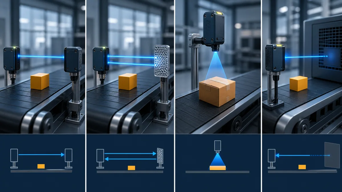
The four principal photoelectric sensor types are through-beam (opposed), retroreflective, diffuse reflective, and background-suppression or distance-settable sensors. All use an emitter and receiver, but their optical paths differ. A through-beam target interrupts light between separate emitter and receiver housings. A retroreflective target interrupts the round trip between one powered sensor and a reflector. A diffuse target returns light to a sensor in the same housing. A background-suppression sensor evaluates return position or distance so it can accept a target while rejecting a farther background.
Purpose-built arrangements include clear-object sensors, fork or slot sensors, fiber-optic heads, focused-spot or laser sensors, contrast/mark sensors and distance-measuring devices. Those are not automatically “better” versions of the four main types; they solve narrower optical, space, feature-size or measurement problems.
Choose the type from the entire detection contract: positive and negative target populations, optical access, minimum and maximum position, color/transparency/gloss, background distance, contamination, ambient light, effective beam or spot size, target dwell time, output circuit, light-on/dark-on behavior and maintainability. Then select an exact model and prove the installed result. A maximum catalogue range or a successful clean-bench demonstration is not production acceptance.
What this guide owns—and what stays separate
This page compares types within photoelectric sensing
Use this guide after optical sensing is a credible candidate and the remaining task is selecting its arrangement. It owns the type taxonomy, optical-path tradeoffs, output-semantics checklist, worked conveyor choice and installed acceptance evidence.
Cross-family selection has a different owner
If the decision is still inductive versus capacitive versus optical detection, begin with proximity sensor vs photoelectric sensor. That page compares sensing physics, target material, range, environment and PLC integration across families. The photoelectric sensor glossary remains the short definition entity. This page adds depth rather than replacing either one.
Electrical interface depth has dedicated owners
PNP/NPN and sinking/sourcing describe current flow, not the optical arrangement. Use sinking vs sourcing PLC I/O and the PNP/NPN wiring guide when the main job is proving circuit compatibility. Here the electrical discussion is deliberately a selection gate, not a terminal drawing for every product.
| Reader task | Canonical owner | Boundary |
|---|---|---|
| Select a photoelectric arrangement | this types guide | through-beam, reflector, target-return, distance and specialty modes |
| Choose inductive, capacitive or photoelectric | proximity-vs-photoelectric guide | compares different sensing physics |
| Get a concise definition | photoelectric sensor glossary | short entity explanation |
| Match PNP/NPN with PLC input | sinking/sourcing guides | circuit current direction and verified wiring |
| Validate exact model range or pinout | manufacturer data | product/version-specific evidence |
Photoelectric sensor working principle
The receiver evaluates changed light
A photoelectric sensor contains an emitter and a receiver, either in one housing or separate housings. The target changes the amount, position, timing, color or pattern of received light. Electronics compare that change with configured criteria and create a switching or measured output. Omron's classification explicitly distinguishes through-beam, retroreflective, diffuse-reflective and distance-settable methods.
The PLC usually sees only an input state. It does not automatically know whether the state came from a broken beam, returned light, a distance threshold, a reflector, a dirty lens or an internal alarm. Maintainable logic separates the physical meaning (“carton present at inspection point”) from the raw electrical state and records diagnostic information when the device provides it.
Optical path is more important than the marketing family name
Two rectangular sensors can respond oppositely to the same carton. A through-beam receiver normally sees its paired emitter and detects the target by loss of light. A diffuse sensor normally receives little light from empty space and detects the target by increased return. A background-suppression unit may see both target and background but accept only a defined distance zone. Select from this path, not case shape.
| Type | Emitter and receiver | What changes at detection | Main target dependency | Main installation dependency |
|---|---|---|---|---|
| through-beam/opposed | separate housings | target attenuates direct beam | target must block enough effective beam | two-sided access, alignment and two cable routes |
| retroreflective | one housing plus reflector | target attenuates round-trip return | transparency and specular reflection | reflector type, angle, cleanliness and polarization |
| diffuse/energetic | one housing | target returns light | color, gloss, texture, angle and size | sensitivity, background and spot placement |
| BGS/distance-settable | one housing | target return occurs in accepted position/distance | distance curve plus optical properties | target/background separation and teach stability |
| specialty | varies | feature-specific optical change | application-specific | head geometry, amplifier, teach and maintenance |
Through-beam photoelectric sensors
Separate emitter and receiver create a direct path
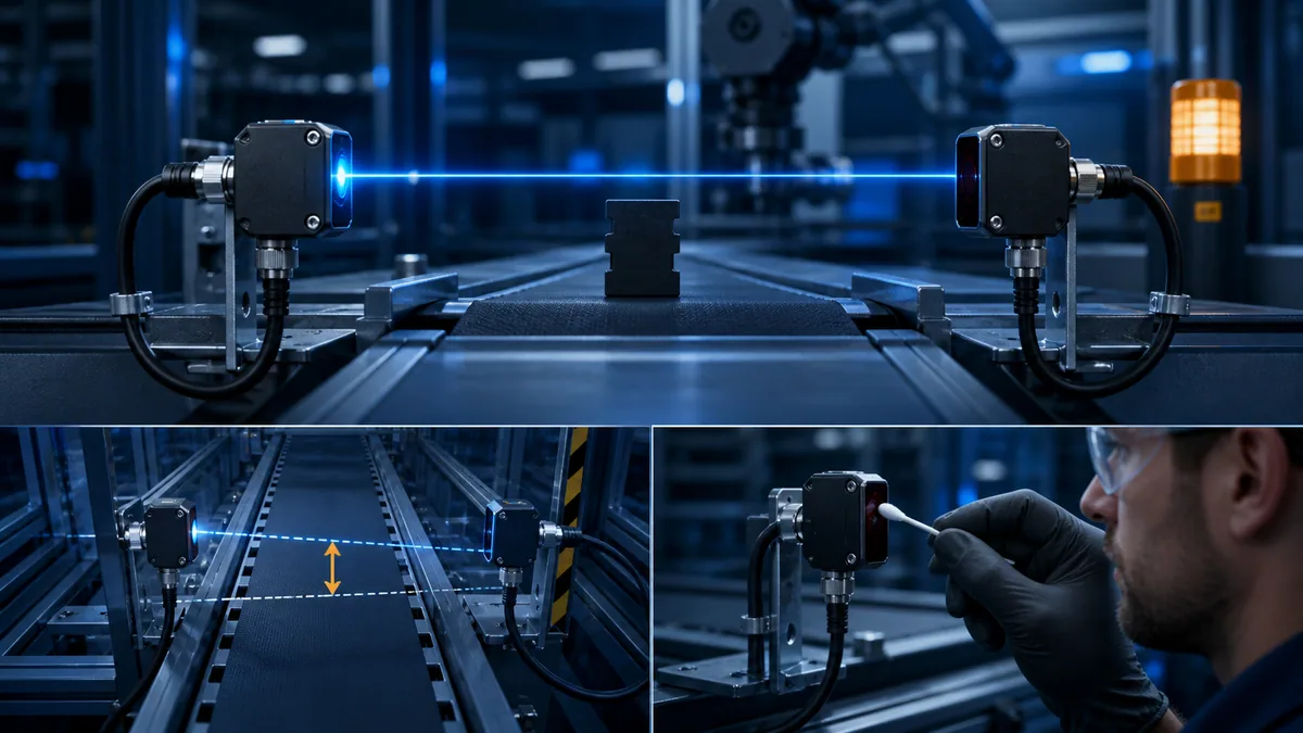
The emitter and receiver are installed opposite each other. Empty-path light reaches the receiver; an object is detected when it attenuates enough of that path. Because the receiver sees the emitter directly, target color and diffuse reflectivity commonly matter less than they do for a diffuse arrangement. Omron notes stable operation and long practical distances as characteristic advantages, while Banner describes opposed sensing as a high-reliability choice where it can be implemented.
Effective beam size controls the smallest detectable feature
The visible centerline is not necessarily the full sensing beam. A thin pin, perforated part or low-profile object can pass through the effective beam without reducing receiver light enough. The manufacturer's minimum-object data is tied to stated distance, sensitivity and accessories. Omron explains that emitter/receiver slits can narrow the beam for smaller-object detection, but narrowing the beam also reduces light and may reduce usable distance or contamination margin.
Two-sided access is the engineering cost
The architecture needs two mounted devices, two alignments and usually two cable routes. Include bracket motion, conveyor tracking and service replacement in the alignment envelope. Put the transmitter and receiver where optics can be cleaned safely. A long catalogue distance does not compensate for a bracket that operators can strike or a receiver hidden behind an unserviceable guard.
| Through-beam advantage | Corresponding cost or limit | Acceptance evidence |
|---|---|---|
| direct emitter-to-receiver path | hardware and wiring on both sides | stable empty-path indication and blocked-path separation |
| commonly strong operating margin | contamination still attenuates direct light | clean, expected-dirty and maintenance-threshold tests |
| less dependent on target return | transparent/small/perforated targets may not block enough | weakest target at all rotations and positions |
| longer supported distances available | alignment envelope grows with distance and bracket motion | edge-of-alignment mapping and replacement repeatability |
| fast electronic response available | PLC input/filter/task can still miss short events | complete sensor-to-program timing budget |
Retroreflective photoelectric sensors
One powered housing uses a reflector on the far side
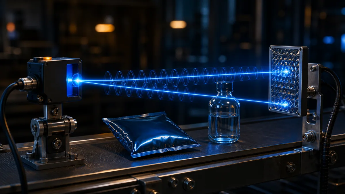
A retroreflective sensor sends light to a prismatic reflector and receives the returned beam in the same housing. The object is detected by interrupting or reducing that round trip. This removes the far-side receiver cable but does not remove the need for two-sided optical access: the reflector must be mounted, aligned and kept suitable for the environment.
Polarization helps reject shiny target returns
A glossy target can reflect sensor light back toward the receiver and imitate the reflector. Polarized retroreflective designs use polarizing optics and the reflector's effect on the returned light to help distinguish the intended path. “Polarized” is not a promise that every mirror-like target, protective film or angle is solved; test the complete surface and angle population.
Clear objects need a purpose-built response window
Transparent bottles or film may attenuate only a small amount of returned light. Dedicated clear-object retroreflective products are designed to resolve that small change and may add automatic adaptation or stability features. Verify container seam, wall count, label, cap, fill, bubbles, condensation, reflector and every permitted rotation. A general retroreflective device does not become clear-object capable through sensitivity alone.
Diffuse photoelectric sensors
The target supplies the return light
In an ordinary diffuse arrangement, emitter and receiver share a housing. Empty space returns little light; an object reflects emitted light into the receiver. The one-sided mechanical layout is attractive, but target optical behavior becomes central. A light matte target can return far more light than a dark, small, glossy or angled target at the same distance.
Rated distance depends on a stated reference target
Omron explains diffuse rated sensing distance using a standard sensing object such as white paper under specified conditions. A quoted distance is therefore not a material-independent boundary. Compare the exact product's response or excess-gain curves with the darkest, smallest, farthest and most angled production targets and with the strongest nearby background.
Sensitivity cannot manufacture separation
Raising sensitivity may make a weak target visible, but it can also accept the background, glare, lens contamination or adjacent reflections. The useful quantity is the stable window between the weakest positive target and strongest negative scene. If that window collapses across production variation, move to another optical path, improve mechanical guidance or use a distance-based mode.
Background-suppression and distance-settable sensors
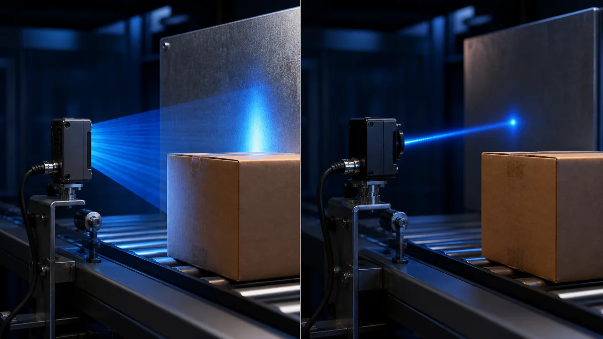
BGS separates a target plane from a farther background
Background-suppression (BGS) sensors use optical geometry, triangulation, position-sensitive reception, time-of-flight or another distance method to reduce response to objects beyond a set boundary. IEC 60947-5-2:2019 includes type-D background-suppression definitions and requirements. The exact implementation and performance curve remain product-specific.
Background suppression is not background immunity
The target needs adequate separation from the nearest background across target and bracket tolerances. Dark or glossy targets, angled surfaces, spot position and minimum/maximum teach conditions can still affect performance. Some applications use foreground suppression or defined background reference behavior instead. Prove the intended target at its nearest and farthest positions and the background at its nearest position.
| Scene | Ordinary diffuse risk | BGS/distance opportunity | Proof required |
|---|---|---|---|
| dark carton before bright conveyor rail | rail returns more light than target | accept target distance, reject farther rail | darkest/farthest carton and nearest/brightest rail |
| target moves in depth | return changes with distance | configured distance zone may separate states | all product and bracket positions |
| shiny angled pack | return may disappear or flare | distance method may reduce reflectance dependence | full angle and finish matrix |
| no stable background separation | sensitivity window collapses | BGS may still lack geometric margin | redesign path or guiding; do not force teach |
| background itself moves | false detections vary with machine state | another geometry or reference may be needed | every background state and restart condition |
Live mini-lab
Try it: press START, then STOP
A stop-dominant seal-in rung: START latches the motor output through its own contact, and STOP breaks the circuit.
Watch the output lamp: it stays on after START until you press STOP.
Free · no signup to try · runs in your browserOpens plcsimulationsoftware.com — same team
Specialty photoelectric sensor types
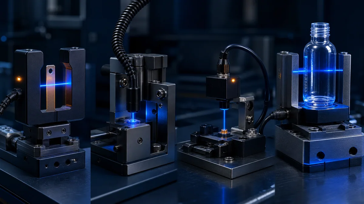
Fork and slot sensors integrate opposed optics
A fork sensor places emitter and receiver in the two arms of a U-shaped housing. Alignment is mechanically fixed, making it useful for labels, web edges, tabs, small components and position features that fit within the slot. The fixed gap, throat depth and effective beam must match the mechanism; a fork body that interferes with travel or traps contamination is not a good trade.
Fiber-optic sensors move the optical head
Fiber systems place small emitting and receiving tips near the target while the amplifier remains in a more accessible location. They help in tight spaces, high-feature-density areas or where a tiny spot is needed. Fiber material, bend radius, routing, cut/termination, head mounting, heat exposure and contamination affect the usable signal. A flexible cable is not permission to crease or crush the fiber.
Focused, laser and contrast sensors solve feature problems
A focused spot can detect a small feature that would fit inside a broad beam. Laser sources can provide small, visible spots and longer reach, but eye-safety class, reflective target behavior and alignment require model-specific attention. Contrast or mark sensors evaluate color/brightness differences at a controlled distance and angle; they are not general object-presence sensors merely because they switch an output.
Distance and IO-Link devices add information, not automatic truth
Some photoelectric sensors expose measured distance, signal strength, alarms, teach state, counters or configuration through an analogue output or IO-Link. IEC 60947-5-7:2024 addresses proximity devices with analogue and/or corresponding digital output. More data improves diagnostics only when the value, quality, units, update, limits and failure behavior are defined and tested.
| Specialty type | Best-fit problem | New dependency introduced | Test focus |
|---|---|---|---|
| fork/slot | tab, label, edge or small feature crosses fixed gap | part must fit and cross effective beam | min feature, lateral offset, web flutter and contamination |
| fiber optic | tight space or remote amplifier | fiber routing, bend, head and signal loss | replacement route, bend, dirty head and worst target |
| focused spot/laser | very small feature or precise edge | spot placement and reflective behavior | minimum feature at maximum motion |
| contrast/mark | printed registration contrast | print/color/finish and controlled standoff | every ink/substrate lot and speed |
| clear-object | small attenuation through transparent target | container/film state and stable reference | seam, label, contents, droplets and rotation |
| distance/measuring | position or analogue distance | units, update, curve, quality and target response | range endpoints, angle, invalid return and recovery |
Difficult targets change the type decision
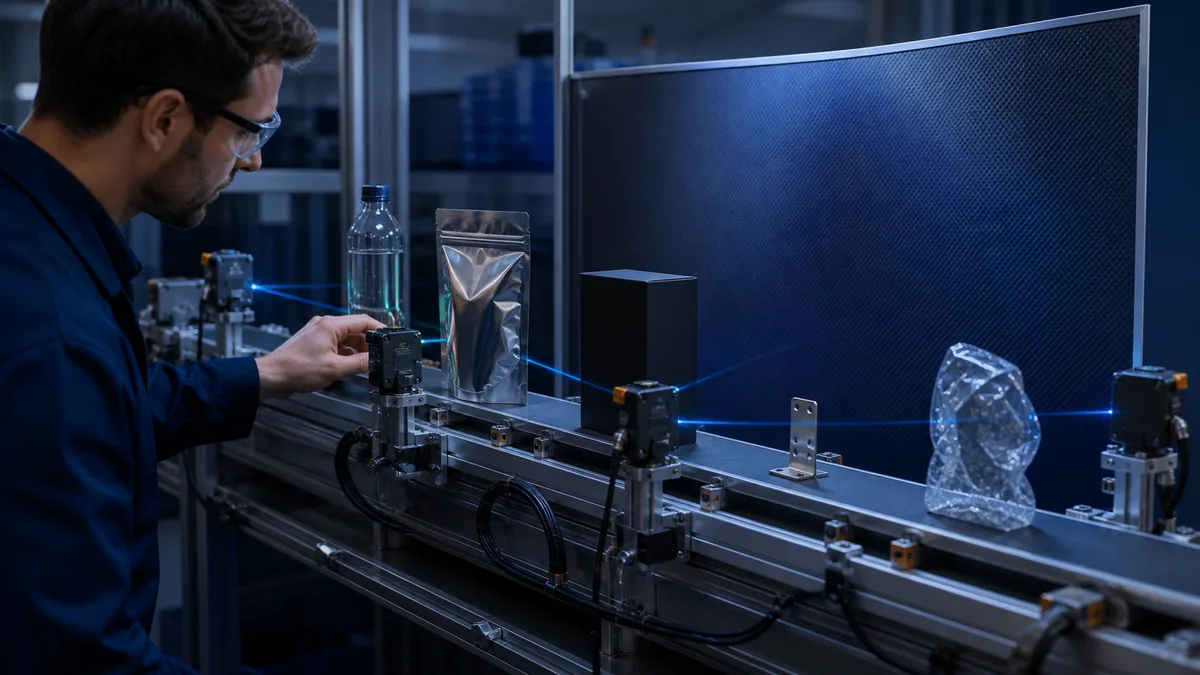
Clear targets transmit too much light
Clear containers, film and glass may not block enough of an opposed or retroreflective path. Their response changes with wall count, seam, curvature, label, contents, bubbles, condensation and angle. Use a purpose-built clear-object method and test the complete sample population. Teaching on the label alone converts a container-presence problem into a label-presence problem.
Glossy targets redirect light
Specular surfaces can return light directly, return it away from the receiver or imitate a reflector. Polarized retroreflection, changed mounting angle or a distance-based method may help. Preserve protective film, wet/dry surface and maximum angle in the acceptance set.
Dark targets absorb light
Dark matte material can create a weak diffuse return. Moving closer within the supported envelope, using through-beam or retroreflective interruption, selecting an appropriate spot/source, or using supported distance sensing may improve separation. Maximum sensitivity can also accept the background and is not a substitute for a stable margin.
Small and fast targets need beam and time budgets
A small target must intersect enough of the effective beam. Its event must then survive sensor response, output switching, input filtering, I/O update and PLC task timing. For a 12 mm feature moving at 1.5 m/s, geometric dwell is 0.012 m ÷ 1.5 m/s = 0.008 s, or 8 ms before beam-size effects. Every component in the signal chain must handle the actual minimum event with margin.
| Timing element | Evidence to obtain | Acceptance question |
|---|---|---|
| geometric target dwell | minimum feature length, maximum speed and effective beam geometry | how long can the physical optical state exist in the worst case? |
| sensor response and release | exact-model datasheet values under the configured mode | can both leading and trailing transitions settle inside the available dwell? |
| output and field interface | output mode, any configured delay and interface update behavior | does the electrical transition preserve the optical event? |
| PLC input filter and module update | approved hardware configuration and measured/raw transition trace | can the input module present the event before it disappears? |
| PLC task and application logic | task period, priority, event handling and count evidence | can the application observe one event exactly once at maximum production rate? |
Do not add worst-case delays as if every value has the same definition; response, release, update and task phase may be specified differently. Build the timing model from exact documentation, then confirm it with a controlled-speed test and a trace at the raw input boundary.
| Target challenge | Likely failure | Candidate direction | Acceptance samples |
|---|---|---|---|
| clear bottle or film | too little attenuation or unstable return | dedicated clear-object opposed/retro or controlled distance | seams, rotations, label, fill, droplets and condensation |
| glossy pouch or metal | reflection imitates/avoids path | polarized retro, BGS/distance or changed angle | finish, angle, film and wet/dry states |
| dark matte carton | weak diffuse return | through-beam, retro, closer diffuse or distance mode | darkest lot, print, position and dirty optics |
| tiny feature | target fits within effective beam | fork, fiber, focused spot or slit | smallest feature at every offset and speed |
| irregular bag | silhouette moves around sensing point | guided feature, multiple paths or different geometry | all fill, sag, wrinkle and orientation states |
Installed margin, alignment and environment
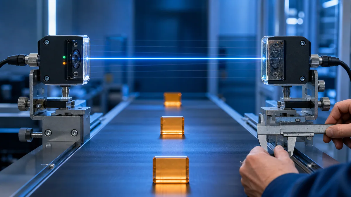
Rated distance is not the installed operating window
Manufacturer rated distance is defined with stated equipment, target, reflector and conditions. Installed gap also contains target motion, conveyor tracking, bracket tolerance, vibration, thermal movement and replacement tolerance. Compare the entire envelope with the exact model's stable sensing data—not with a typical maximum in a family table.
Map the alignment window
For through-beam and retroreflective systems, deliberately move the receiver or reflector horizontally and vertically to find stable edges, then center the installation with recorded margin. For diffuse and BGS arrangements, move the target through every allowed distance and angle. A stability or excess-gain indicator can be valuable evidence, but interpret it using the device manual.
Test expected contamination and ambient light
Oil mist, dust, flour, fibers, water droplets and scratches reduce or scatter light. Direct sun, high-frequency lighting, welding and adjacent optical sensors can interfere depending on modulation and construction. Test the credible environment and define the cleaning or alarm threshold. Do not smear an unknown substance on optics as an improvised test; use an approved, repeatable method compatible with the lens.
Light-on, dark-on, PNP and NPN
Light-on and dark-on describe optical output logic
Light-on means the output becomes active under the product's defined received-light condition; dark-on means it becomes active under the defined absence or reduction of light. That physical meaning differs by sensing arrangement. A diffuse sensor often receives more light when a target is present; a through-beam receiver often receives less. Therefore “light-on” is not a portable synonym for “target present.”
PNP and NPN describe current direction
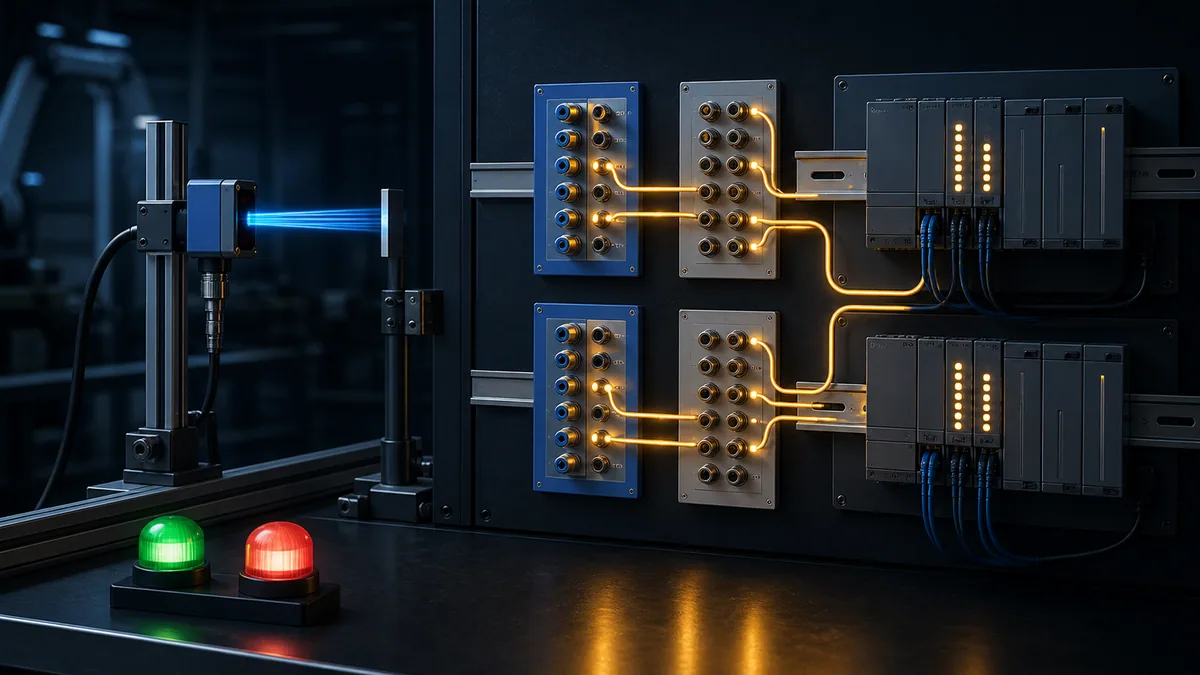
PNP/NPN describe output transistor behavior and must be matched to the exact PLC input circuit and common. They do not define whether the output is normally open/closed or light-on/dark-on. A product may offer selectable behavior or complementary outputs. Verify supply, common, connector pinout, load/current, off-state leakage and voltage drop from the exact manual.
Define raw and semantic states separately
Name the raw input from its circuit meaning and map it to an application meaning such as carton_present_validated. Record the expected sensor LED, terminal voltage, PLC channel indicator, raw tag and semantic state for both target-present and target-absent cases. This prevents a replaced sensor's output setting from silently reversing machine logic.
| Axis | Example choices | What it answers | What it does not answer |
|---|---|---|---|
| optical type | through-beam, retro, diffuse, BGS | how light travels and target is detected | output current direction |
| switching behavior | light-on, dark-on, NO/NC depending on product | when output is active | whether output is PNP or NPN |
| electrical output | PNP, NPN, push-pull, relay, analogue, IO-Link | how signal interfaces electrically | whether target means light or dark |
| application semantic | carton present, gap clear, label detected | what machine state should mean | exact sensor pinout or safety integrity |
Worked conveyor selection example
Define the detection contract
A packaging conveyor must count opaque cartons at up to 1.5 m/s. Cartons range from 120 to 500 mm long, 80 to 450 mm high, and include brown, white, dark print and glossy tape. The detection point has access on both sides, but the far side needs an additional cable route. The nearest fixed background is 150 mm beyond the product path. Dust accumulation is expected between scheduled cleaning windows. Missing a carton is more costly than adding the far-side cable.
Compare viable types
Through-beam is the initial candidate because cartons can interrupt a direct beam and two-sided access exists. Retroreflective is also viable and uses one powered side, but reflector state and glossy tape must be tested. Ordinary diffuse is easy to install yet depends more on the darkest/farthest return and bright background. BGS could separate product from the background if the position window remains wide enough.
| Criterion | Through-beam | Polarized retro | Diffuse | BGS/distance |
|---|---|---|---|---|
| color/print dependence | low candidate risk | low-to-medium | higher | medium/product-specific |
| powered-side wiring | two sides | one side | one side | one side |
| background dependence | low | low | material/sensitivity dependent | distance-window dependent |
| glossy tape risk | attenuation test | polarization/false-return test | return-angle test | target-curve test |
| dirty-state margin | often strong candidate | reflector plus lens affected | target return already weaker | model/target dependent |
| selected for pilot | yes | backup candidate | no | backup candidate |
Pilot the winner and backup
Select a through-beam model only after exact range, effective beam, response, output and environment checks. Build an adjustable pilot with production cartons at minimum/maximum height and lateral positions. Test clean and expected-dirty optics, bracket disturbance, start/stop, maximum speed and power recovery. Pilot a polarized retroreflective backup if far-side wiring cost is material. Preserve both results; “simpler wiring” and “stronger margin” are explicit tradeoffs.
Commissioning and troubleshooting
Commission from optics to application meaning
Verify exact part number and configuration, then power and optical state, alignment/stability, output circuit, terminal voltage, PLC channel state, raw tag, validated tag and machine behavior. Test positive and negative populations. A test that only waves one sample at the sensor does not establish timing, position or false-positive performance.
Troubleshoot the evidence chain in order
When a sensor misses, first reproduce the target and path. Observe the stability/output indicators, then measure the field signal according to the approved procedure, then inspect PLC channel and raw/semantic tags. Change one suspected boundary—target position, optic cleanliness, reflector, bracket, cable or input channel—while retaining before/after evidence. Avoid hiding optical chatter with an arbitrary timer before finding its cause.
| Symptom | First evidence | Likely boundaries | Controlled test |
|---|---|---|---|
| dark target misses | stability/return over target positions | weak diffuse return, distance, angle, dirty lens | compare worst target and background through envelope |
| clear bottle intermittently misses | container rotation and optical indication | seam, label, fill, condensation, wrong mode | indexed sample matrix at fixed setup |
| empty conveyor shows target | background and reflection path | excessive sensitivity, shiny rail, reflector imitation | cover/remove one background surface under approved test |
| input chatters | optical indicator, terminal voltage and raw tag | vibration, threshold margin, loose wiring, noise | correlate physical, electrical and program timestamps |
| high-speed count is low | target dwell and raw transition capture | spot/beam, sensor response, input filter, task | controlled-speed run with synchronized evidence |
| state reversed after replacement | light/dark and raw mapping | output setting, complementary wire, logic inversion | target-absent/present state table before motion |
Retain an acceptance record
Record selected type and model, firmware/configuration when relevant, reflector/accessories, supply/output, light/dark mode, mounting distances, target/background samples, environmental states, speed, input filter/task, raw and semantic results, faults, actor and date. Photograph mounting and cable route without exposing restricted system data. A replacement must reproduce the approved contract, not merely fit the bracket.
| Release layer | Minimum retained evidence | Reject or investigate when |
|---|---|---|
| identity and configuration | exact sensor, reflector/head/amplifier, accessories, output mode and teach/configuration record | the installed item or configuration cannot be reconciled with the approved selection |
| mechanical and optical path | mounting dimensions, alignment window, target envelope and service access | normal motion, replacement tolerance or expected contamination consumes the stable window |
| target and background population | positive and negative sample matrix with position, orientation and surface state | any required target is missed or any credible non-target is accepted |
| electrical and PLC interface | supply, common, output, terminal state, channel indication, raw tag and semantic mapping | any layer disagrees, chatters or reverses meaning |
| timing and production behavior | minimum dwell model, maximum-speed run, counts and synchronized trace | one physical event becomes zero, two or an indeterminate number of application events |
| faults and recovery | obstruction, dirty-state threshold, cable/power interruption, restart and replacement checks | the fault is hidden, recovery is ambiguous or restart creates an unsafe/unintended command |
| ownership and maintenance | approved baseline, responsible role, cleaning/inspection threshold and change-control reference | nobody owns the evidence or routine service cannot restore the approved state |
Diagnostic answer map
Main photoelectric sensor types
Through-beam uses separate emitter and receiver; retroreflective uses one powered housing plus reflector; diffuse receives light returned by the target; background suppression or distance setting distinguishes a target zone from a farther background. Specialty types adapt the path for clear, tiny, marked or constrained targets.
Best type for a conveyor
There is no universal best. Through-beam is often a strong candidate when both sides are accessible and the target can block the effective beam. Retroreflective reduces far-side wiring. Diffuse simplifies mounting but depends on target return. BGS helps when a stable target/background distance window exists. Pilot the actual target and environment.
Proof before release
Test every positive target and strongest negative background at all permitted positions and speeds, clean and expected-dirty states, bracket/reflector tolerances, start/stop and power recovery. Verify optical indication, electrical signal, PLC raw state, semantic state and required machine response.
Frequently asked questions
What are the main types of photoelectric sensors?
The main types are through-beam, retroreflective, diffuse reflective and background-suppression or distance-settable. They differ in whether light travels to a separate receiver, a reflector, the target itself or a distance-evaluating receiver. Specialty types include clear-object, fork, fiber-optic, focused-spot, contrast and distance-measuring sensors.
How does a photoelectric sensor work?
An emitter sends light and a receiver evaluates the light that arrives. A target interrupts, attenuates, reflects or changes the position/timing of that light. Electronics convert the detected change into a switching or measured output. The exact response depends on optical arrangement, target, background, configuration and product limits.
What is a through-beam photoelectric sensor?
A through-beam sensor has a separate emitter and receiver mounted opposite each other. An object is detected when it blocks enough of the effective beam. It often offers strong margin and less dependence on target color, but requires two-sided access, alignment and usually two cable routes.
What is a retroreflective photoelectric sensor?
A retroreflective sensor puts emitter and receiver in one powered housing and sends light to a reflector on the far side. The target interrupts the round-trip beam. Polarization can help with glossy objects, while clear objects usually require a dedicated clear-object design and tested attenuation window.
What is a diffuse photoelectric sensor?
A diffuse sensor emits light and detects the portion reflected by the target back into the same housing. It provides simple one-sided mounting, but sensing distance and stability depend more on target color, gloss, size, angle and background than a direct through-beam path.
What does background suppression mean?
Background suppression uses optical geometry or distance evaluation to accept a target in a selected zone while reducing response to a farther background. It is not universal immunity: target/background spacing, surface, angle, teach point and product-specific curves still require validation.
Which photoelectric sensor type detects clear bottles?
Use a purpose-built clear-object arrangement, often an opposed or retroreflective design with sensitivity and adaptation intended for small attenuation. Test seams, rotations, labels, caps, liquid, bubbles, droplets and condensation. No family label proves a particular clear container will be stable.
Does PNP mean normally open or light-on?
No. PNP describes output current direction. Normally open/closed and light-on/dark-on describe switching behavior. Optical type is another independent choice. Verify all three axes plus the PLC input common and exact connector diagram.
Why does a photoelectric sensor false trigger?
Common causes include a bright or moving background, specular reflection, dirty optics, reflector damage, bracket vibration, marginal teach setting, ambient/interfering light, electrical faults, wrong light/dark setting or program timing. Compare the optical indicator, terminal signal, raw input and semantic state before changing filters.
Can a normal photoelectric sensor be used as a machine-safety sensor?
Not merely because PLC logic stops motion when it changes. Safety functions require the applicable risk assessment, safety-rated architecture, device capability, diagnostics, fault response, validation and lifecycle. Ordinary object-detection sensors and standard PLC inputs do not gain a safety rating from their application name.
Sources, review scope, and limitations
This guide was reviewed on August 30, 2026. Product families, specifications, standards and support pages change. Verify the selected model's current manual, accessories, ratings and application data.
- IEC 60947-5-2:2019 proximity-switch scope and background-suppression type — IEC
- IEC 60947-5-7:2024 proximity devices with analogue/digital output — IEC
- Photoelectric sensor overview and classifications — Omron Industrial Automation
- Photoelectric sensor overview — Omron Industrial Automation
- Photoelectric sensor terms, sensing distance and light-on definitions — Omron
- Photoelectric engineering data and excess-gain interpretation — Omron
- Technical explanation for photoelectric sensors — Omron
- Slits for small-object through-beam detection — Omron
- Photoelectric sensing modes — Banner Engineering
- Clear and reflective target sensing — Banner Engineering
- Selecting a photoelectric functional principle and output — SICK
- Foreground-suppression definition — SICK
- Photoelectric sensor basics and installation — Balluff
- Photoelectric industrial sensor type examples — Balluff
- Multifunction optical principles and configurable outputs — Balluff
- Photoelectric sensor light/dark and PNP/NPN operating instructions — AutomationDirect
- Photoelectric sensor selection guide — Pepperl+Fuchs
- Photoelectric sensors and object detection — ifm
- NIST SP 800-82 Rev. 3 Guide to Operational Technology Security — NIST
- 29 CFR 1910.147 control of hazardous energy — OSHA
The taxonomy, selection example, matrices, timing calculation, diagnostic map and generated illustrations are original editorial teaching material. They are not product drawings, certified wiring diagrams, a safety function, an optical/radiation assessment, a chemical-compatibility claim, an installed range guarantee or a replacement for manufacturer application review.
This page does not authorize installing, wiring, bypassing, forcing, energizing, aligning inside hazardous motion, defeating a guard or changing a running machine. Qualified and authorized personnel must use the site hazard assessment, hazardous-energy and electrical safe-work rules, exact device and PLC documentation, optical-source precautions, approved change control and validated commissioning and recovery procedures.
Now run it · free · no signup
Switch a proximity sensor and watch the PLC input
Present and remove a target, watch the sensor switch and check that the PLC input follows. Free browser lab — no signup required to finish it.
Ownership disclosure: PLC Programming IO and PLC Simulation Software are operated by the same publisher.
PLC Programming IO Editorial Team
Industrial automation education, references, and software testing
The PLC Programming IO Editorial Team publishes sourced industrial-automation education and documents how material is reviewed, tested, and corrected. A team byline means the publisher is responsible for the page; it does not represent a fictional person or imply an engineering licence.
Coverage:
- • PLC programming concepts and examples
- • Vendor software tutorials and comparisons
- • SCADA, HMI, protocols, and instrumentation
- • Training, careers, and reference material
Review standard:
- • Prefer primary and official sources
- • Record software versions when material
- • Separate tested facts from estimates
- • Publish material corrections
Important scope note
This site provides education, not project-specific engineering approval. Safety, code, and compliance decisions require a qualified person with access to the actual machine and jurisdiction.