PID Program for PLCs: Design, Implementation and Commissioning
Build a dependable PLC PID program with fixed-cycle execution, engineering-unit scaling, modes, tracking, output limits, anti-windup, diagnostics and staged commissioning.
Review status: Editorially reviewed against cited Siemens, Rockwell Automation and Schneider Electric controller documentation; exact instruction behavior, units, timing, safety functions, process limits and commissioning procedures require verification for the installed platform and process
Direct answer
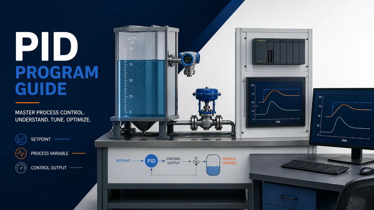
A dependable PLC PID program is more than a PID instruction with three tuning values. It is a control module that reads a valid process variable in known engineering units, executes at a known interval, compares that value with a bounded setpoint, calculates a controller output, respects actuator limits, transfers safely between manual and automatic modes, reports why it cannot control, and produces evidence that technicians can diagnose.
The practical implementation order is: define the process and control objective; scale and validate the process variable; choose action direction; run the controller on a documented fixed cycle; configure output and setpoint limits; implement manual tracking and bumpless transfer; coordinate permissives, interlocks and bad-measurement behavior outside the tuning terms; expose diagnostics and trends; then commission from signal checks through manual operation, low-risk closed-loop tests and approved tuning. Tuning cannot repair incorrect scaling, variable execution time, a saturated actuator, a reversed action setting or an unreliable sensor.
This guide focuses on implementation and commissioning. For deeper treatment of gain, integral time, derivative time and tuning methods, use the separate PID tuning guide. The diagrams here are conceptual training aids, not field wiring, safety logic or process operating instructions.
Define the loop before writing logic
State the controlled and manipulated variables
Write one sentence that identifies what must be held, what the controller may move, the normal range and the important disturbances. For example: “Maintain vessel level in the approved operating band by positioning the outlet valve while inlet flow varies.” This prevents a common design failure: configuring a mathematically valid controller around the wrong signal or final element.
Capture the process gain direction. If increasing the output makes the process variable increase, the loop usually needs one action direction; if increasing output makes the process variable decrease, it needs the other. Vendors name direct and reverse action differently, so verify the definition in the exact instruction manual and prove it at low risk in manual mode. Never infer action solely from whether the actuator is called “fail open” or “fail closed.”
| Design item | Question to answer | Evidence to retain |
|---|---|---|
| controlled variable | What physical condition should follow the setpoint? | tag, units, normal range and acceptable deviation |
| manipulated variable | What actuator command can change the condition? | output tag, units, limits and fail behavior |
| disturbance | What changes the process without being commanded by this loop? | expected range, rate and operating scenarios |
| action direction | Does more output raise or lower the measured variable? | manual step observation and approved sign convention |
| dynamics | How quickly does the measurement respond after output moves? | trend showing delay, response and settling |
| control objective | Is the priority tight regulation, gentle motion, fast recovery or another outcome? | measurable acceptance criteria |
Separate basic control from protection
A PID loop regulates a process; it is not a substitute for an independently engineered safety function. High-high trips, burner management, overspeed protection, machinery safety and other risk-reduction functions require the applicable hazard assessment and safety lifecycle. Ordinary permissives and interlocks can constrain whether the PID output is applied, but changing a tuning value must not silently change an independent trip threshold.
Define who owns each decision. The PID module can report requested output, limited output, mode and status. A separate equipment module can decide whether a pump or valve is available. A protection layer can force the process to its engineered safe state. Clear ownership makes testing and incident review possible.
Understand what the PID calculation contributes
Proportional, integral and derivative terms have different jobs
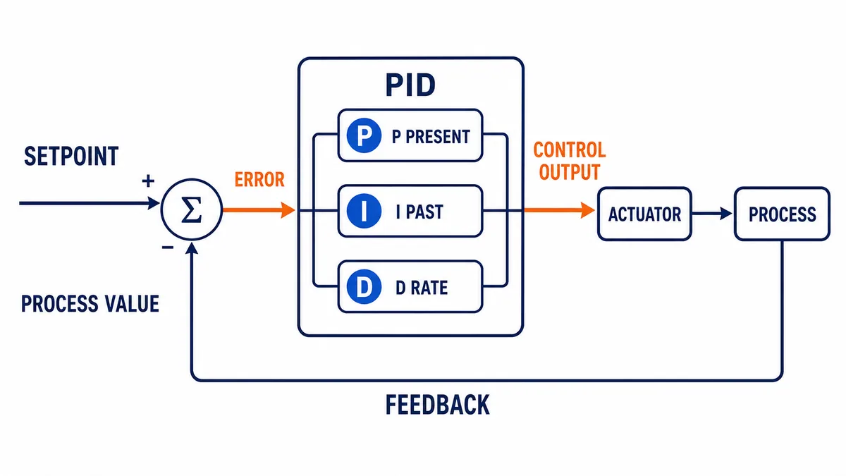
Proportional action responds to present error. Integral action accumulates error over time and can remove persistent offset, but it can also accumulate while the actuator cannot move farther. Derivative action responds to rate of change and can add damping, but it is sensitive to measurement noise and implementation details. The terms operate inside a feedback loop; their effect depends on process dynamics, execution interval, scaling, filters, limits and vendor algorithm form.
| Term | Responds to | Useful contribution | Implementation risk |
|---|---|---|---|
| proportional | current error | immediate correction proportional to deviation | excessive gain can create oscillation or sensitivity |
| integral | accumulated error over time | removes sustained offset when actuator authority exists | windup during limits, holds or unavailable equipment |
| derivative | error or measurement rate, depending on form | anticipatory damping for suitable processes | noise amplification, derivative kick and timing sensitivity |
| bias/feedforward | known base demand or measured disturbance | reduces how much feedback correction must do | wrong units, sign or unvalidated operating-region assumptions |
Do not copy tuning values between algorithm forms
Parallel, ideal, dependent-gain and independent-gain forms do not interpret parameters identically. Some products express integral and derivative in seconds or minutes; others use repeats per unit time or gains. Some apply derivative to error, others to process variable. A value that worked in one PLC is not automatically equivalent in another. Record controller family, instruction revision, algorithm form, units, action, execution interval and every filter or limit with the as-left tuning.
Run the controller at a known interval
Prefer a periodic or explicitly timed execution context
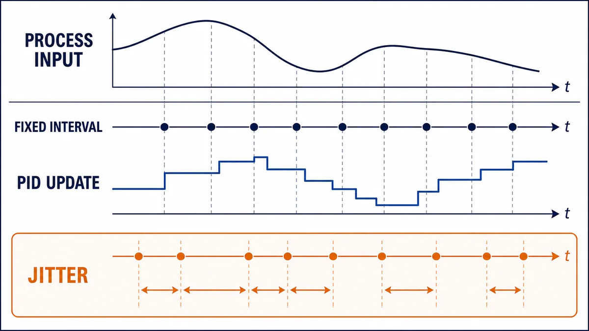
Time is part of the integral and derivative calculations. Rockwell documents timing modes and recommends periodic-task execution for appropriate Logix function-block control. Schneider distinguishes PID blocks that measure elapsed time from fixed-cycle variants intended for short, precise cycles. Siemens PID instructions also have documented execution and calling requirements. The common engineering lesson is not to guess: use the platform’s supported calling pattern and configure its cycle parameter to match actual execution.
An ordinary continuous PLC scan varies with communications, conditional logic, other tasks and online activity. If the PID assumes one interval while calls arrive at another, integral and derivative behavior can change even though the displayed tuning values do not. If a vendor block internally measures elapsed time, that reduces one class of error but does not make missed calls, long gaps or asynchronous signal updates irrelevant.
Match signal update, task period and process speed
A fast controller task cannot create fresh information when an analog input or networked transmitter updates slowly. Conversely, a task that is too slow can miss meaningful process movement. Document the sensor response, input-module filter and update, network production interval, controller execution interval, output update and actuator response as one timing chain.
| Timing surface | What to record | Fault exposed by the record |
|---|---|---|
| sensor/transmitter | damping and response time | measurement lags real process |
| input/interface | filter, conversion and update interval | repeated or delayed PV samples |
| communications | cyclic update, timeout and age/quality | stale data treated as current |
| controller | task period, priority, actual scan and overruns | variable or missed PID calls |
| output/interface | update and hold/fault behavior | command applied later than calculated |
| actuator/process | dead time, slew and response | control demand exceeds physical capability |
Monitor task overlap, maximum execution time and missed-call indicators. The target is not the smallest possible period; it is a supported, repeatable interval appropriate to the process and total signal chain.
Scale and validate every signal
Put setpoint and process variable in the same engineering units
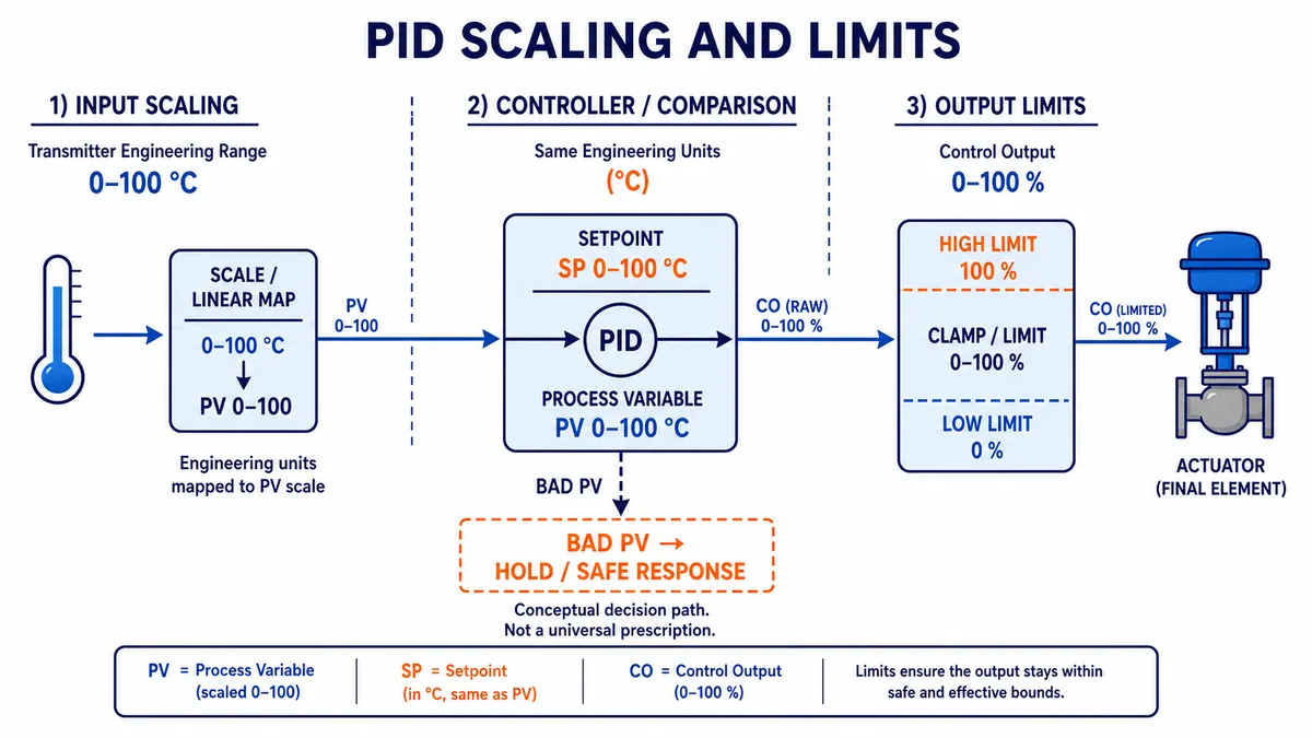
Scale the raw input once, document the range and give the PID a process variable with explicit units. If the transmitter represents 0–100 °C, both the displayed PV and SP should use that interpretation unless the selected block explicitly requires normalized values. Check low, mid and high points against a traceable source. Do not tune around a scaling error.
The controller output should also have a clear convention, commonly 0–100 percent demand before mapping to an analog output, drive reference or valve command. If an actuator’s useful range is narrower, represent that deliberately through limits, characterization or equipment logic rather than hiding it in unexplained scaling constants.
Treat bad quality as a mode decision, not a number
An out-of-range, stale, substituted or diagnostically bad PV should not quietly enter the PID as an ordinary value. Define the response from the process hazard and operating requirements: hold a last command for a strictly bounded interval, track a fallback value, transfer to manual, drive an engineered fallback through equipment logic, or stop the controlled equipment. There is no universal safe choice.
| Validation | Example condition | Program response to define |
|---|---|---|
| raw electrical range | under-range, over-range or channel fault | declare bad quality and prevent normal automatic calculation |
| engineering range | PV outside credible physical bounds | alarm, reject or qualify according to approved requirements |
| age | timestamp exceeds maximum acceptable age | mark stale and execute specified degraded response |
| rate of change | physically implausible jump | flag suspect; avoid masking a real fast event without analysis |
| source state | simulated, forced or substituted | display state and control who may enable it |
| redundancy | sources disagree beyond tolerance | identify selected source and disagreement response |
Live mini-lab
Try it: press START, then STOP
A stop-dominant seal-in rung: START latches the motor output through its own contact, and STOP breaks the circuit.
Watch the output lamp: it stays on after START until you press STOP.
Free to start · runs in your browserOpens plcsimulationsoftware.com — same team
Build an explicit operating-mode state model
Distinguish manual, track, automatic and unavailable
“Manual/auto” is often too coarse. A maintainable loop usually needs states or status for operator manual, external/cascade setpoint, tracking, initializing, bad PV, actuator unavailable, output held, output limited and automatic. The controller instruction’s internal mode and the plant module’s commanded mode are not necessarily the same thing; reconcile them and expose the effective mode.
Every transition needs entry conditions, output behavior, setpoint behavior, integral/derivative behavior and operator indication. Define what happens after download, warm restart, loss and restoration of a permissive, communications recovery and return of a valid transmitter. Automatic restart may be appropriate for one utility loop and unacceptable for another.
| Transition | Entry checks | Desired evidence |
|---|---|---|
| initialize → manual/track | valid configuration, known output source and equipment state | initialized flag, effective mode and tracked value |
| manual → auto | valid PV/SP, actuator available, output tracked and approved request | no unintended output step; event records actor/time |
| auto → manual | manual command source valid and bounded | manual station begins at current applied demand |
| auto → unavailable | failed permissive, equipment fault or bad measurement | first-out reason and defined output/fallback behavior |
| unavailable → ready | fault cleared, quality restored and restart conditions met | deliberate re-entry path; no hidden automatic bump |
Implement bumpless transfer by tracking the applied output
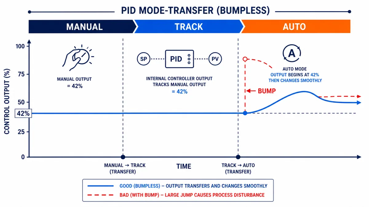
Before automatic control takes ownership, align the controller’s internal state so its first automatic output starts at or near the output already applied to the process. Rockwell’s PID documentation describes bumpless manual-to-auto behavior and tracking/back-calculation concepts. Exact parameters differ by platform, but the goal is consistent: do not let mode selection create an unrelated process disturbance.
Track the actually applied demand when downstream selection or limits can differ from the raw PID request. If the controller tracks 65 percent while a downstream clamp applies 40 percent, the stored integral state may still produce a jump when the clamp is removed.
Constrain the output and prevent integral windup
Use limits that reflect the current operating envelope
Output limits can represent equipment capacity, minimum stable operation, split-range allocation, ramp constraints or a temporarily reduced envelope. Keep raw requested output, limited output and applied output as separate observable values. A generic 0–100 percent clamp is not enough when a valve is only permitted between 20 and 80 percent in a particular state or when a drive has a separate acceleration limit.
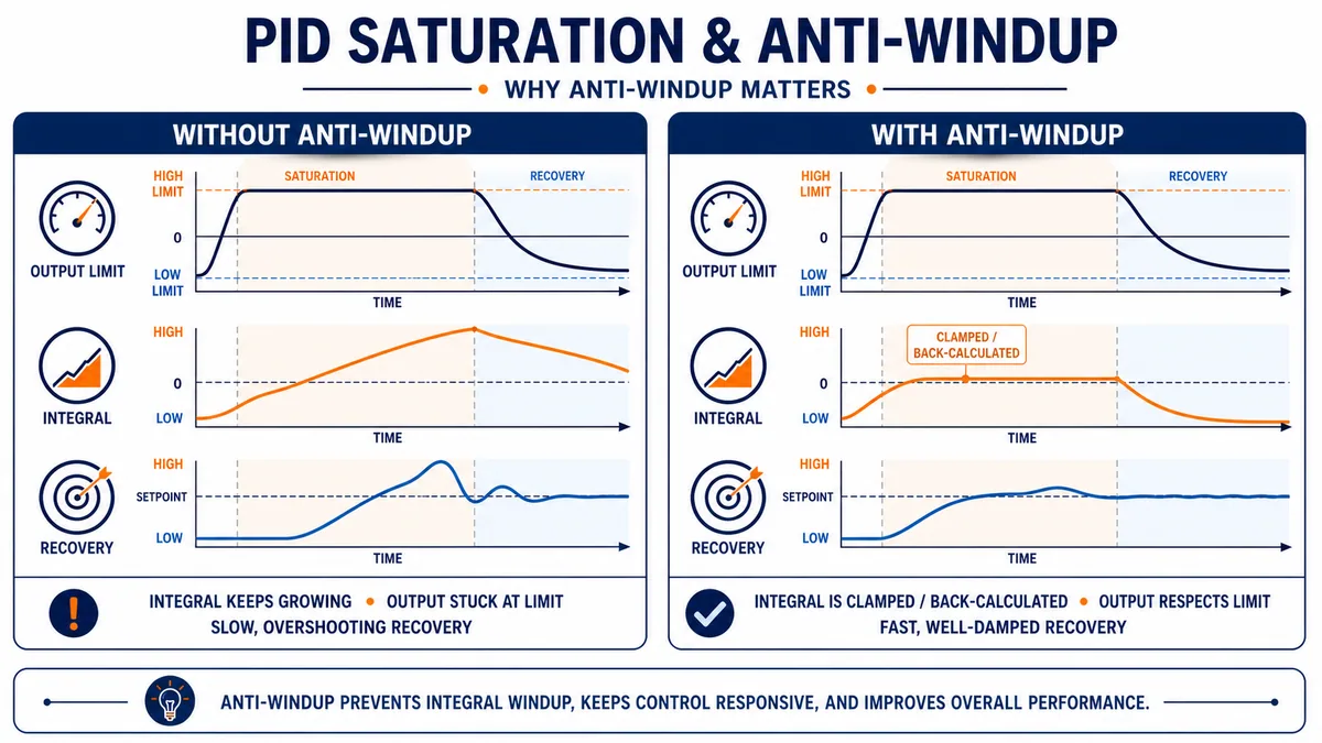
Dynamic limits require careful coordination. If an upstream or downstream block constrains the output but the PID is unaware of the constraint, integral action may continue accumulating error that the final element cannot correct. Feed the applied limitation or track value back using the exact vendor-supported mechanism.
Anti-windup protects recovery after saturation
When the requested output reaches a limit, additional integral accumulation cannot create more actuator authority. Without anti-windup, the stored integral term can keep growing and delay recovery after error reverses or capacity returns. Controller implementations may freeze, clamp or back-calculate the integral contribution. Rockwell explicitly documents anti-reset windup for output limits; other platforms provide their own status and parameters.
| Output condition | What it means | Diagnostic response |
|---|---|---|
| PID request at high limit | controller wants more positive authority | investigate disturbance, capacity, tuning and action direction |
| PID request at low limit | controller wants more negative authority | investigate opposite disturbance, leakage, minimum-load behavior or sign |
| requested ≠ limited | a software operating envelope is active | expose the active limit and owner |
| limited ≠ applied | equipment, selector, ramp or interlock changed demand | expose downstream constraint and track applied value |
| output changes, PV does not | actuator/process path is not responding as expected | inspect feedback, energy, mechanical condition and measurement |
| output chatters | noise, excessive gain, resolution or state conflict may exist | trend terms, modes and raw/filtered values before retuning |
Structure the PLC program for diagnosis
Keep acquisition, control and actuation boundaries visible
A useful module separates input acquisition/quality, setpoint management, mode arbitration, PID execution, output selection/limiting, equipment command and diagnostics. The separation can be routines, function blocks, add-on instructions or structured code according to the platform. The purpose is to make ownership testable, not to maximize abstraction.
Use typed or consistently named values for PV_Raw, PV_Eng, PV_Quality, SP_Requested, SP_Effective, Mode_Requested, Mode_Effective, CV_PID, CV_Limited and CV_Applied. The names are examples, not a required standard. What matters is that a technician can determine which value changed and why without editing logic online.
| Program layer | Responsibility | Minimum diagnostics |
|---|---|---|
| acquisition | read, scale, timestamp and qualify PV | raw, engineering value, quality, source and age |
| setpoint | select local/remote/cascade request and apply limits/rates | requested/effective SP and active constraint |
| mode | arbitrate operator, sequence, quality and availability | requested/effective mode and first-out reason |
| PID | execute documented instruction at documented interval | P/I/D contributions where available, error and status bits |
| output conditioning | limit, characterize, ramp and select demand | requested, limited, selected and applied values |
| equipment interface | command final element and read feedback | ready/running/position/fault and discrepancy |
| presentation/history | show and retain control evidence | units, quality, modes, limits, events and synchronized trends |
Avoid conditional calls that silently freeze controller state
Do not simply stop calling the PID instruction whenever a permissive is false unless the vendor explicitly defines that pattern and the state behavior meets requirements. A skipped call can freeze timers, integral state, mode transitions and diagnostics. It is often clearer to call the block on its required schedule while placing it in a supported tracking/manual state and separately controlling whether its demand reaches equipment.
Design the HMI and historian around decisions
Show why the loop is not controlling
The faceplate should show PV, SP, requested/effective mode, raw/limited/applied output, quality, action direction, output limits, active constraints, controller status and equipment availability. Permissions should distinguish ordinary setpoint/mode actions from tuning, limit and configuration changes. Record actor, time, old value, new value and reason where the control system supports it.
A trend should align PV, SP, requested output, applied output and mode/limit events on synchronized time. A PV-only trend invites guesswork. Trend at a resolution that preserves relevant dynamics; excessive historian compression can hide short oscillation, saturation or a transfer bump.
| Operator question | Data needed on one view |
|---|---|
| Why is PV not reaching SP? | PV, SP, error, requested/applied output, limits and equipment feedback |
| Why did output jump? | requested/effective mode, track value, PID terms and transition event |
| Is the loop saturated? | high/low limit status, raw request, limited/applied demand and duration |
| Can automatic mode be selected? | PV quality, permissives, actuator availability and inhibit reason |
| Did tuning improve behavior? | comparable before/after trends, disturbance context and configuration revision |
Commission the PID program in evidence stages
Prove the signal and actuator path before closing the loop
Commission under the approved site procedure, hazard controls and process authority. Start with controller/instruction version and configuration review. Verify transmitter range and engineering-unit scaling at multiple points. Confirm displayed quality and bad-signal response. In manual mode, prove that a bounded output change moves the correct final element in the expected direction and that feedback represents actual movement. Observe process direction, delay and rate without exceeding the approved envelope.
Only then prove automatic-mode prerequisites, tracking and bumpless transfer. Begin closed-loop operation under a stable, low-risk condition with conservative settings approved for the process. Introduce only authorized setpoint or disturbance tests. Record every configuration change and retain synchronized trends. Stop if the actuator saturates unexpectedly, the PV behaves implausibly, protection demands action or the response exceeds approved limits.
Use a test matrix rather than one successful trend
| Test stage | Test case | Pass evidence |
|---|---|---|
| static configuration | instruction form, units, timing, action and limits match design | peer-reviewed record tied to software revision |
| input | low/mid/high PV and bad/stale/simulated quality | value, units and state agree at controller and HMI |
| manual output | approved bounded commands and feedback | correct actuator, direction, range and response |
| mode | manual→track→auto and auto→manual | no unintended bump; mode/reason recorded |
| limits | high/low and dynamic constraints | raw, limited and applied output remain distinguishable |
| availability | actuator unavailable and restored | defined track/fallback and deliberate recovery |
| controller | approved setpoint/disturbance response | acceptance criteria met without unexplained saturation |
| restart | warm/cold restart and communications restoration as applicable | deterministic mode, output, SP and diagnostics |
| regression | normal, boundary, fault and recovery cases after change | signed results and updated as-left record |
Troubleshoot the loop from evidence, not tuning guesses
Classify the symptom before changing parameters
If PV never moves while output changes, inspect the actuation and measurement path. If output is pinned at a limit, ask whether the process lacks capacity or has a disturbance before increasing gain. If the loop oscillates only after a task or network change, compare actual timing and data age. If switching to auto creates a jump, inspect tracking and effective output. If the displayed PV is plausible but quality is stale, repair the data path before tuning.
| Symptom | First comparison | Common classes of cause |
|---|---|---|
| PV moves away from SP in auto | output step direction versus PV response | wrong action, wrong actuator, inverted scaling or process change |
| slow sustained offset | error, output limits and available actuator capacity | integral disabled/too weak, saturation, leakage or undersized final element |
| repeating oscillation | period versus task, sensor and process delays | excessive gain/integral, valve stiction, dead time or interacting loop |
| noisy output | raw PV, filtered PV and derivative contribution | measurement noise, derivative setting, gain or resolution |
| jump entering auto | applied output versus track/internal output | missing/incorrect tracking or stale manual value |
| long recovery from limit | integral term/status and saturation duration | windup, wrong limit integration or insufficient capacity |
| good on bench, poor on plant | actual timing, real dynamics, equipment and disturbances | model mismatch, network/input update or mechanical nonlinearity |
| intermittent mode loss | first-out transition reason and synchronized events | quality timeout, permissive chatter, command arbitration or restart logic |
Make one justified change at a time and retain before/after evidence. Tuning several parameters while also changing scaling or filters destroys the ability to attribute improvement. If the root cause is valve stiction, transmitter damping, task jitter or insufficient equipment capacity, parameter changes may only move the symptom.
Diagnostic answer map for search and AI-assisted implementation
| Query | Concise answer | Important qualification |
|---|---|---|
| How do you program PID in a PLC? | Scale and validate PV, execute the vendor PID block at a known interval, configure action/limits/modes, track applied output and test in stages. | Use the exact controller manual and approved process procedure. |
| Where should a PID instruction run? | In the platform-supported periodic or explicitly timed context with its configured interval matching real execution. | Sensor and output update rates must also suit the process. |
| Should PID run every PLC scan? | Only if the instruction supports that calling pattern and actual elapsed time is handled correctly. | A variable continuous scan can change time-based behavior. |
| What units should PV and SP use? | The same documented engineering units, unless the selected instruction explicitly requires normalized values. | Verify multiple scaling points before tuning. |
| What is bumpless transfer? | Aligning controller internal output/state to the applied manual demand before automatic control takes ownership. | Track the applied value when downstream limits or selectors exist. |
| What is PID anti-windup? | Logic that prevents or corrects integral accumulation while output is constrained. | Implementation differs by controller family. |
| What happens when the transmitter fails? | The program detects bad/stale quality and enters the process-specific approved track, hold, fallback or stop state. | There is no universal safe output. |
| Why is a PID output stuck at 100%? | The controller is demanding maximum authority because of error, direction, capacity, disturbance or configuration. | Inspect actual actuator response and limits before retuning. |
| Why does PID oscillate? | Possible causes include aggressive tuning, delay, timing, noise, stiction, saturation or loop interaction. | Use aligned PV/SP/output/mode evidence to distinguish them. |
| Is PID logic safety logic? | No; basic PID regulation does not replace independently engineered safety functions. | Follow the applicable hazard and safety lifecycle. |
Choose the next PID implementation guide
Use the broad PID control definition and terminology when you need a compact reference before implementation. Move to advanced process-control strategies for cascade, feedforward, override and multivariable boundaries, or run the bounded pump PID flow-control example when the task is an end-to-end modeled loop. When the platform is already fixed, use the Delta PLC PID example, Mitsubishi FX5U PID guide or RSLogix 5000 PID guide; each owns its exact instruction, project and diagnostic details while this page remains vendor-neutral.
Frequently asked questions
What is a PID program in a PLC?
It is the controller instruction plus the surrounding signal validation, timing, mode, tracking, limiting, actuation, diagnostics and operator logic needed to regulate a physical process. The surrounding module is what makes the calculation maintainable and safe to commission.
How often should a PLC PID execute?
Use a stable interval appropriate to the process and supported by the exact instruction. Configure any cycle-time parameter to match actual execution, then monitor task overruns and the complete sensor-to-actuator timing chain. Faster is not automatically better.
Does the process variable have to be scaled before PID?
Usually, using explicit engineering units makes configuration and diagnosis clearer. Some blocks accept normalized values, but PV and SP must share the interpretation required by that block. Validate low, middle and high points before tuning.
How do I choose direct or reverse action?
Determine experimentally and from design evidence whether increasing controller output increases or decreases the controlled variable. Then apply the exact vendor definition of direct/reverse action. Prove the result with an authorized low-risk manual test.
What causes a bump when switching a PID to automatic?
The controller’s internal output or integral state is not aligned with the demand currently applied to the actuator. Implement the vendor’s tracking or bumpless-transfer mechanism and track downstream applied demand when selectors or limits intervene.
What is integral windup in a PLC PID?
It is continued integral accumulation while the requested correction cannot be applied, commonly because output is saturated, equipment is unavailable or another block limits demand. It can cause slow or overshooting recovery after the constraint clears.
Should I stop calling the PID block when an interlock is false?
Not by default. Skipping calls can freeze state or violate instruction timing. Prefer the vendor-supported manual/tracking/hold pattern while separately enforcing the equipment interlock, unless verified documentation specifies another design.
What should be visible on a PID faceplate?
Show PV and quality, SP, requested/effective mode, raw/limited/applied output, limits, action, availability, active constraint and diagnostic status. Authorized users may also need tuning and configuration views with audit records.
Can PID tuning fix a valve that sticks or an undersized heater?
No. Tuning cannot create actuator authority or remove mechanical defects. Compare requested output, actual feedback and process response, then correct equipment, measurement, timing or capacity problems before optimizing parameters.
How should a PID program be tested?
Use staged tests for configuration, signal scaling/quality, manual output and feedback, mode transitions, limits, unavailable equipment, closed-loop response, restart and regression. Retain synchronized trends and an as-left configuration tied to the software revision.
Sources, review scope, and limitations
This guide was reviewed on August 28, 2026. Product behavior and documentation change; verify the installed firmware, programming software, instruction revision and current manufacturer documentation.
- SIMATIC S7-1200/S7-1500 PID control function manual, November 2025 — Siemens
- Anti-reset windup and bumpless transfer for PID — Rockwell Automation
- Timing modes in Logix Designer — Rockwell Automation
- Tasks, programs and routines in Logix Designer — Rockwell Automation
- PlantPAx PPID instruction — Rockwell Automation
- PID function block — Schneider Electric Machine Expert
- FB_PID pin description — Schneider Electric Machine Expert
- ControlLoopLibrary guide — Schneider Electric
- IEC 61131-3:2025 programmable-controller programming languages — IEC
- 29 CFR 1910.147, control of hazardous energy — OSHA
The figures are conceptual functional illustrations, not controller code, P&IDs, electrical drawings, safety architectures, tuning prescriptions or field procedures. This guide does not authorize connecting, programming, forcing, bypassing, isolating, tuning, starting or testing installed equipment. Qualified, authorized personnel must follow the site hazard assessment, hazardous-energy and electrical safe-work requirements, approved process limits, safety lifecycle, exact manufacturer instructions and controlled commissioning/change procedure.
Now run it · free to start
Tune a PID loop against a live process model
Change the setpoint and loop terms, then measure overshoot, settling time and error in a browser PID lab. Free to start, nothing to install.
Ownership disclosure: PLC Programming IO and PLC Simulation Software are operated by the same publisher.
PLC Programming IO Editorial Team
Industrial automation education, references, and software testing
The PLC Programming IO Editorial Team publishes sourced industrial-automation education and documents how material is reviewed, tested, and corrected. A team byline means the publisher is responsible for the page; it does not represent a fictional person or imply an engineering licence.
Coverage:
- • PLC programming concepts and examples
- • Vendor software tutorials and comparisons
- • SCADA, HMI, protocols, and instrumentation
- • Training, careers, and reference material
Review standard:
- • Prefer primary and official sources
- • Record software versions when material
- • Separate tested facts from estimates
- • Publish material corrections
Important scope note
This site provides education, not project-specific engineering approval. Safety, code, and compliance decisions require a qualified person with access to the actual machine and jurisdiction.