Studio 5000 PID: ControlLogix PID/PIDE Example and Tuning
Build and commission a Rockwell Logix PID loop with the right PID, PIDE or PPID choice, periodic execution, engineering-unit scaling, manual/auto tracking, output limits, evidence-led tuning and troubleshooting.
Review status: Editorially reviewed against current Rockwell Automation Studio 5000 Logix Designer PID, PIDE, function-block timing, task and PlantPAx PPID documentation; the worked values and diagrams are original teaching examples, and exact controller support, firmware, instruction revision, units, timing, process limits and field procedures require project-specific verification
Direct answer
To implement an RSLogix 5000 PID loop reliably, first identify the exact Logix controller, firmware, Studio 5000 Logix Designer version, routine language and process-control library. Choose the classic PID instruction, enhanced PIDE instruction or PlantPAx PPID object from those project requirements—not from the shortest tutorial. Scale the process variable (PV) and setpoint (SP) into documented engineering units, execute the calculation at a known interval, keep requested, limited and applied control variable (CV) values visible, define manual/automatic/tracking transitions, and prove every limit and failure response before tuning the live process.
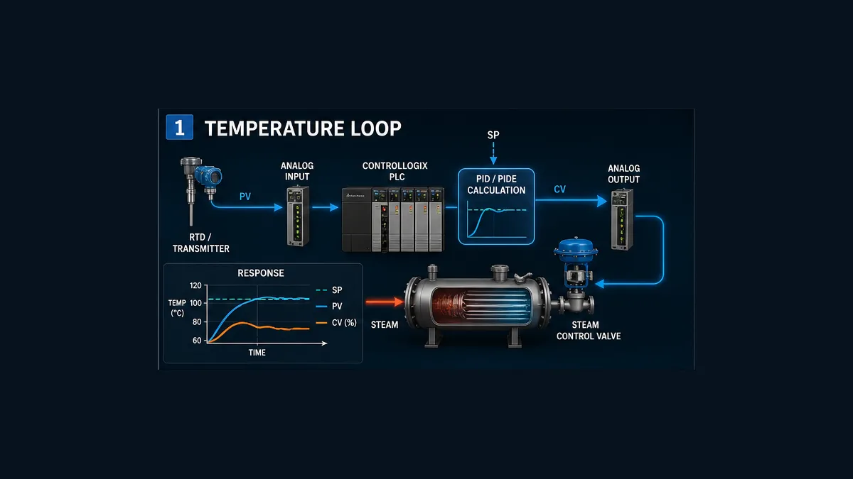
For a new ControlLogix temperature loop using the enhanced instruction, a defensible starting architecture is a PIDE instance in a function-block routine under a periodic task. Rockwell’s current PIDE reference says the default PIDE timing mode is periodic and describes a function-block routine in a periodic task as the easiest implementation; the block then uses that task’s update rate as its delta time. Structured Text is also documented. The classic PID instruction is available in Ladder Diagram and Structured Text and executes on enabled scans, so its configured loop update and actual calling schedule must agree.
This page is a vendor-specific implementation guide. Use the broader PLC PID program guide for controller-independent architecture and the worked PID control-system example for the underlying control calculation. The example below is a training design, not an importable controller project, a tuning prescription or permission to operate an installed process.
RSLogix 5000 versus Studio 5000: what name should the guide use?
Engineers still search for “RSLogix 5000 PID,” while current Rockwell documentation uses Studio 5000 Logix Designer. Treat RSLogix 5000 as the familiar or legacy product name in conversation and Studio 5000 Logix Designer as the current engineering environment. Neither name identifies the controller revision or instruction behavior precisely enough for a change record.
Record all of these before implementation:
| Compatibility surface | Why it changes the answer | Evidence to retain |
|---|---|---|
| controller catalog and family | instruction and task support differ across Logix targets | controller properties and approved hardware inventory |
| controller firmware | project compatibility, instruction members and behavior can change | as-found and intended firmware revision |
| Logix Designer major/minor version | project conversion and online-edit behavior depend on version | installed software inventory and project version |
| routine language | PID, PIDE and supporting constructs are not identical across languages | routine properties and reviewed source export |
| instruction/library revision | PlantPAx process objects and project libraries have their own lifecycle | instruction signature, library release and source |
| process design basis | action, ranges, limits and response objectives come from the real process | approved loop sheet, P&ID and control narrative |
| safety and interlocks | ordinary PID control cannot replace risk-reduction functions | hazard review, cause-and-effect and proof-test ownership |
A forum answer that says “use PIDE” may be directionally useful but is not a compatibility decision. A maintained system may correctly retain a classic PID instruction because that is the verified standard, while a new PlantPAx project may intentionally use PPID. The project architecture, support boundary and migration risk matter as much as the feature list.
Choose PID, PIDE or PPID deliberately
The classic PID instruction
The Studio 5000 PID instruction controls a process variable such as temperature, flow, pressure or level. Rockwell documents it in Ladder Diagram and Structured Text. It uses a PID structure plus operands including the process variable, tieback and control variable. The instruction exposes configuration for scaling, gains, action, timing, limits, manual behavior and related functions.
Classic PID is a reasonable choice when it is the established, supported project standard; when an existing loop is already proven and migration adds risk; or when its feature and language model fit the application. “Classic” does not mean “safe to configure casually.” Its loop-update setting and actual execution must match, and the surrounding quality, mode, actuator and evidence logic remains essential.
The enhanced PIDE instruction
Rockwell’s PIDE reference documents Function Block and Structured Text use, multiple operating modes, program/operator control, engineering-unit parameters, initialization, cascade/ratio support, windup coordination and a built-in autotune facility subject to product support and licensing. The official example places a PIDE in a function-block routine under a periodic task; the documented Structured Text form calls the instruction with its PIDE tag after assigning inputs.
PIDE is often the better fit when a project needs its enhanced mode, initialization, cascade or diagnostic model and the team can support that architecture. It is not automatically better merely because it has more parameters. More capability also creates more states to specify, expose and test.
The PlantPAx PPID instruction
PPID belongs to the PlantPAx process-instruction ecosystem. It combines control with a larger process-object model intended for PlantPAx projects, including standardized ownership, alarms, permissives, interlocks, faceplate interaction and configuration conventions described by the applicable library documentation. Use it when the PlantPAx version, controller target, library lifecycle, HMI strategy and project standards call for it.
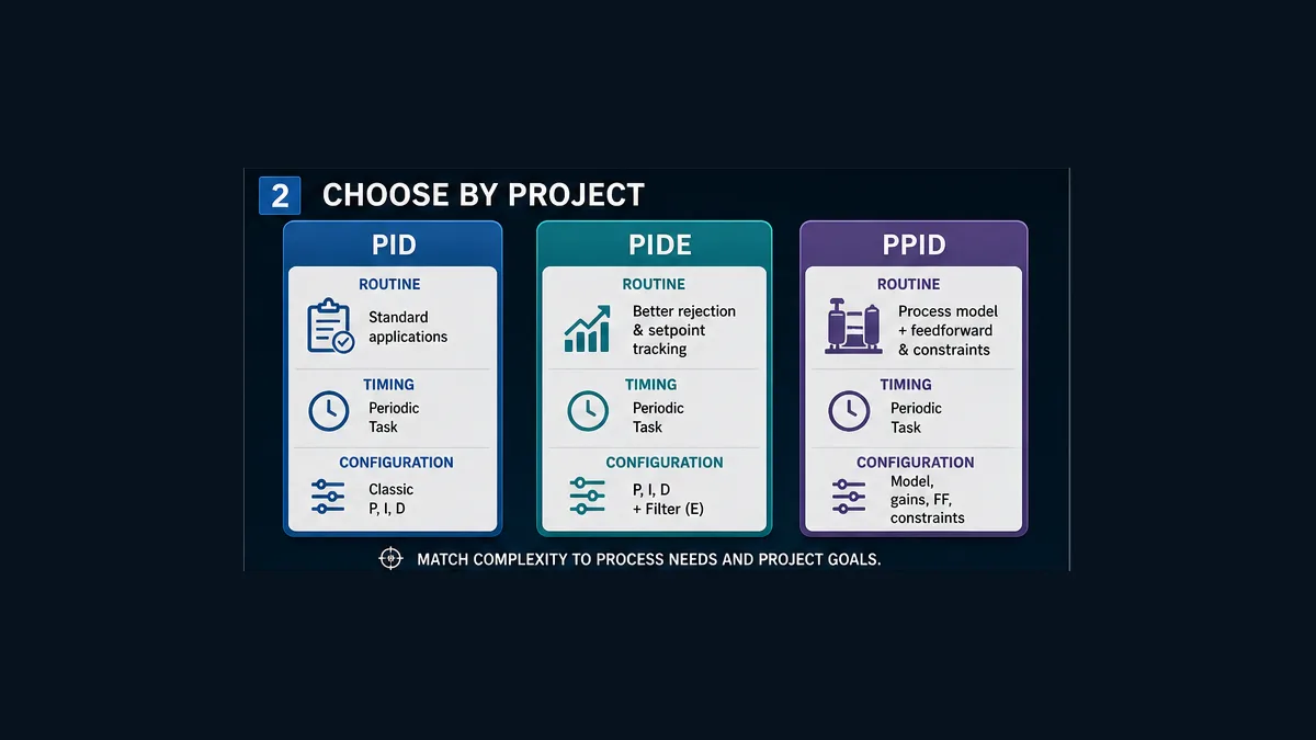
Do not choose PPID because an image or acronym suggests a model-predictive controller. PPID is a PlantPAx PID process instruction; exact functions depend on the cited release. Consult the current PPID reference and the project’s verified library rather than inferring behavior from its name.
| Decision question | PID | PIDE | PPID |
|---|---|---|---|
| is it already the validated site standard? | often in established Logix projects | common in enhanced process-control designs | common only within compatible PlantPAx designs |
| documented language surface | Ladder and Structured Text | Function Block and Structured Text | verify the exact PlantPAx release and controller support |
| timing model | configure and reconcile loop update with execution | documented periodic, oversample and real-time sampling concepts; verify selected mode | follow the process-library and task guidance for the release |
| mode/initialization surface | manual, tieback and internal software manual behaviors are documented | richer program/operator, manual/auto/cascade and initialization interface | integrated process-object conventions and faceplate model |
| migration burden | lowest when retaining a proven classic loop | requires tag/mode/faceplate/test mapping | requires PlantPAx library, HMI and lifecycle alignment |
| correct selection basis | installed project standard and required behavior | required enhanced behavior plus team support | approved PlantPAx architecture—not keyword popularity |
Worked ControlLogix PIDE example: a jacketed temperature loop
Define the process before the tags
The teaching example is loop TIC_201. A temperature transmitter measures product temperature in a jacketed vessel. The controller manipulates a steam-valve demand. The target is to maintain a bounded product-temperature setpoint while inlet conditions and steam supply vary.
These numbers make the example concrete; they are not field recommendations:
| Design item | Teaching value | Field value must come from |
|---|---|---|
| PV engineering range | 20–100 °C | transmitter, input configuration and approved loop sheet |
| normal SP band | 40–80 °C | process operating envelope and recipe authority |
| CV convention | 0–100% demand | valve/positioner, output scaling and equipment module |
| example task period | 500 ms | measured process dynamics and complete signal timing chain |
| example normal output limits | 10–90% | valve capability, process constraints and operating state |
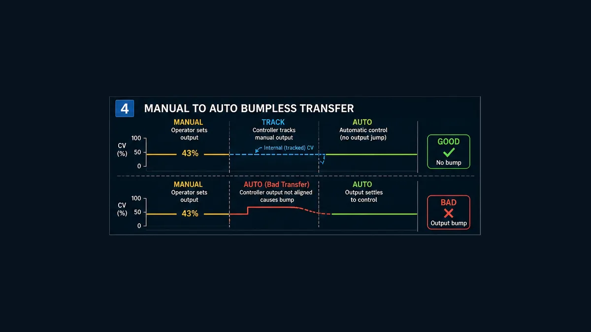
| example transfer point | 43% applied CV | current safe applied demand during an authorized test |
| control objective | stable recovery with limited overshoot and valve travel | signed process acceptance criteria |
Write the direction statement before selecting controller action: “An increase in applied steam-valve demand is expected to increase product temperature after the process delay.” Prove the sign with an approved small manual step. Do not infer controller action from the words “heating,” “air-to-open,” “fail closed,” “direct” or “reverse” alone; manufacturer terminology and signal inversions can make a label misleading.
Separate regulation from protection. High-high temperature trips, relief protection, burner/steam-system safeguards and other risk-reduction functions require their own engineered lifecycle. The PID can report demand and constraints, but changing Kp, an SP limit or an output limit must not silently alter an independent trip.
Build a tag contract around the instruction
The PIDE tag is not the whole loop. Create an explicit contract for the measurement, quality, operator requests, effective modes, calculated demand, constraints, applied output, equipment availability, feedback and evidence. Download the Studio 5000 PID loop design register as a vendor-aware planning worksheet. It is intentionally not an L5X import because controller projects require exact catalog, firmware, library, naming, ownership and safety review.
| Surface | Example tag concept | What must remain observable |
|---|---|---|
| measurement | TIC_201_PV |
value, raw source, engineering units, quality, age and substitution state |
| setpoint | TIC_201_SPReq / effective SP |
requester, bounds, rate limit, ownership and accepted value |
| controller instance | TIC_201_PIDE |
configuration, current modes, status, faults and as-left revision |
| raw demand | TIC_201_CVReq |
controller-calculated request before external constraints |
| limited demand | TIC_201_CVLim |
active high/low/dynamic limit and reason |
| applied demand | TIC_201_CVApplied |
value actually delivered after selection, interlock and output handling |
| actuator state | TV_201_Available / position |
availability, command/feedback mismatch, quality and first-out fault |
| mode | request / effective / source | operator-versus-program ownership and transition result |
| evidence | synchronized trend and events | SP, PV, requested/limited/applied CV, mode, quality, availability and time |
Scale and qualify the process variable once
Configure the input channel and scaling so the loop receives a meaningful temperature with documented units. Then prove low, midpoint and high source values against a traceable signal. Record raw value, scaled value, quality and timestamp. A page showing 65.0 is insufficient if nobody knows whether it is degrees Celsius, percent of span, stale data or a substituted value.
Range checking alone is not quality. A broken communications path can leave a plausible last value. Define electrical/module fault, under-range, over-range, stale age, forced/simulated state and substitution separately. Rockwell’s PIDE example documents wiring an analog input fault indication to PVFault; the official behavior described there forces Manual and prevents the output from winding up or down when PV is unavailable. The project wrapper should also manage faults or stale states that do not arrive as the exact module fault bit.
Do not tune until source-to-tag scaling passes. A 0–100 °C transmitter interpreted as 0–100 percent can still produce a smooth trend and a badly wrong control objective.
Live mini-lab
Try it: press START, then STOP
A stop-dominant seal-in rung: START latches the motor output through its own contact, and STOP breaks the circuit.
Watch the output lamp: it stays on after START until you press STOP.
Free to start · runs in your browserOpens plcsimulationsoftware.com — same team
Make controller timing deterministic
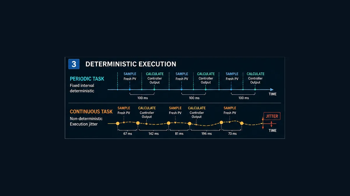
Integral and derivative actions depend on elapsed time. A fixed tuning set does not mean fixed behavior if the calculation interval changes. For the PIDE route, create an appropriate periodic task, place the function-block routine in a scheduled program under that task, select and verify the supported timing mode, and monitor task performance under representative load.
Rockwell documents the PIDE default timing mode as periodic. In a periodic task with periodic timing mode, the instruction automatically uses the periodic task update rate as delta time. Its documentation also covers oversample and real-time sampling modes; use those only when their required calling and timestamp model is understood and verified. The safest conclusion is not “500 ms is always correct,” but “the configured mode and measured execution must match the approved design.”
For classic PID, Rockwell documents that the instruction executes every scan while enabled and provides separate PID instruction-timing guidance. Configure the loop-update time and schedule calls using the exact supported pattern. Do not put a time-sensitive loop behind a condition that sometimes prevents the call unless the manual explicitly defines that behavior.
Measure the complete time chain
| Timing surface | Question | Evidence |
|---|---|---|
| sensor/transmitter | how quickly does the measurement represent process change? | damping/filter configuration and response data |
| analog input | how often is a new value produced and what filtering applies? | module configuration and timestamps |
| networked I/O | what are the requested packet/update interval, timeout and age semantics? | connection settings and captured diagnostics |
| controller task | what are configured period, priority, actual executions and maximum duration? | task monitor data under normal and peak load |
| PIDE/PID | which timing mode/update setting is active? | as-left instruction configuration |
| output | when is a new command transmitted or held? | output/module/drive update evidence |
| actuator/process | what dead time, slew, stiction and response are measured? | manual step trend and maintenance findings |
A 10 ms task cannot create 10 ms measurement information from a slow transmitter and filtered network input. A one-second task can be entirely appropriate for a slow thermal process but unacceptable for a fast pressure loop. Select a repeatable supported interval fast enough to represent the process dynamics without wasting controller capacity or responding mainly to noise.
Configure the PIDE wrapper in a reviewable order
The following is an implementation sequence, not copy-paste production code:
- Inventory controller, firmware, Logix Designer and instruction/library revision.
- Create the periodic task and scheduled program/routine according to the measured timing design.
- Define the PIDE tag and surrounding loop data structure using the site naming and ownership standard.
- Scale the PV and calculate explicit good/bad/stale status before normal automatic control.
- Bound SP requests and expose requested versus effective SP.
- Assign PIDE PV, SP, mode and fault-related inputs using members documented for the exact revision.
- Execute the instruction once per intended calculation event.
- take its engineering-unit or percent CV result according to the selected configuration; apply approved external selection, equipment availability, limits or fallback without hiding the raw request.
- feed the applied/initialization or windup state back through the documented parameters where downstream constraints can differ from the controller request.
- expose effective mode, initialization, limit, windup, fault and timing status to diagnostics and HMI.
- capture synchronized trend and event evidence before any tuning trial.
The official Structured Text example follows this conceptual shape:
PIDE tag PV assignment
PIDE tag PV-fault assignment
PIDE(PIDE_tag)
output assignment from the PIDE engineering-unit CV
Use the exact member names and syntax from the installed Logix Designer help. Avoid copying an online example that writes directly from a module tag to an output without the project’s scaling, quality, mode, equipment and constraint ownership. A short example demonstrates the instruction call; it does not constitute a maintainable loop module.
For the classic instruction, Rockwell publishes the Structured Text signature:
PID(PID, ProcessVariable, Tieback, ControlVariable,
    PIDMasterLoop, InHoldBit, InHoldValue);
That signature still requires a configured PID structure and an approved surrounding design. Do not assume a PIDE tag can replace a PID structure or that gain numbers map one-to-one.
Design manual, automatic and tracking behavior
Separate requested mode from effective mode
An HMI request for Auto is not proof the loop is in Auto. Automatic control may require valid PV, bounded SP, initialized state, available actuator, permitted process state and a supported timing configuration. Record ModeRequest, ModeEffective and a rejection/first-out reason. Show whether control authority is Operator or Program where the selected PIDE architecture uses those concepts.
Specify each transition:
| Transition | Entry conditions | Output behavior | Evidence |
|---|---|---|---|
| initialize → manual/track | valid configuration and known applied output | controller state aligns to approved current demand | mode, initialization and applied CV trend |
| manual → automatic | good PV, valid SP, available actuator and aligned internal state | first auto output stays within bump tolerance | high-resolution CV and mode transition |
| automatic → manual | valid bounded manual demand source | manual station takes ownership at applied demand | request/effective mode, actor and CV |
| automatic → bad PV | diagnostic or stale rule active | specified degraded mode/fallback, no hidden windup | PV value, quality, age, CV and reason |
| automatic → unavailable actuator | equipment module withdraws availability | output handoff and tracking follow design | request/limited/applied CV and availability |
| unavailable → ready | fault cleared and recovery criteria satisfied | deliberate re-entry; no surprise auto restart | first-out, acknowledgement and recovery trend |
Make transfer bumpless at the applied output
Bumpless transfer means the first controller-owned demand begins near the demand already applied, within a project-defined tolerance. Rockwell’s classic PID documentation describes tieback and bumpless manual-to-auto behavior. PIDE documentation describes initialization using CVInitReq and CVInitValue; it says the initialization value normally comes from analog-output readback and the request from an output “In Hold” status so startup does not bump the field signal.
Track the applied output rather than only the raw calculation when a downstream selector or constraint changes the result. If PIDE requests 63%, a constraint applies 43%, and internal state tracks 63%, removing the constraint may release an unexpected step. Keep all three values visible.
Apply output limits without hiding saturation
Create separate diagnostics for controller-requested CV, instruction-limited CV, externally constrained CV and actually applied output. Output limits may represent valve travel, minimum stable equipment operation, temporary capacity, split-range selection, environmental constraints or a process operating envelope. Their source and active reason should be visible.
Rockwell’s PID documentation describes anti-reset windup when the output reaches configured maximum or minimum and bumpless transfer concepts. PIDE provides windup and cascade-coordination surfaces documented in its instruction reference. Exact behavior depends on the instruction and configuration; verify it with a saturation-and-recovery test rather than assuming any clamp prevents all windup.
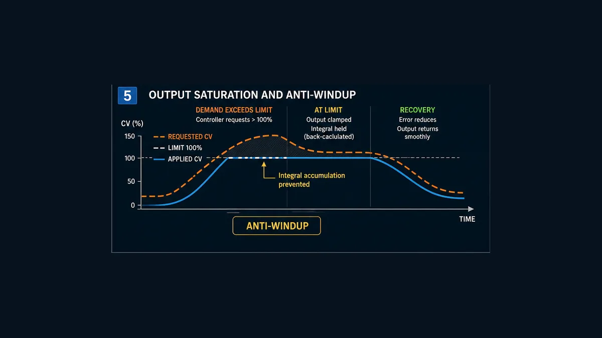
When PV remains below SP while CV is pinned high, the controller may be behaving correctly. Investigate capacity and the final element before increasing gain:
| Evidence | Likely boundary | Next safe check |
|---|---|---|
| requested, limited and applied CV all high; valve feedback follows | process capacity or disturbance | utility supply, heat load, exchanger condition and approved process model |
| requested CV moves; applied CV does not | selection, interlock, output or equipment module | active constraint, availability and output-channel state |
| applied CV moves; feedback does not | positioner, actuator, air/supply or mechanics | command-feedback diagnostics and authorized maintenance |
| feedback moves; PV does not respond | process path, sensor location, isolation or equipment state | field condition, line-up and independent measurement |
| PV responds in wrong direction | action, scaling, wiring or process understanding | return to safe manual state and re-prove the direction chain |
| CV chatters near limit | tuning, noise, quantization, stiction or competing constraints | high-resolution trend, input filter and actuator behavior |
Tune from evidence, not copied numbers
Record the equation form and units first
Rockwell documents dependent and independent gain forms and related equation choices. PIDE also permits choices about whether proportional and derivative terms respond to error or PV; its default treatment is documented to reduce derivative spikes on setpoint changes. Gain labels alone are therefore insufficient. A Ki value from a classic PID example cannot be pasted into PIDE and assumed equivalent.
The as-left record needs:
| Tuning record | Why it matters |
|---|---|
| instruction and revision | defines available members and algorithm behavior |
| dependent/independent equation | changes parameter interpretation |
| proportional/derivative basis | affects setpoint response and derivative kick |
| gain and time units | avoids seconds/minutes or repeats/time confusion |
| task period and timing mode | time is part of I and D behavior |
| PV/SP/CV ranges | scaling changes effective loop gain |
| derivative filter or smoothing | alters noise response |
| output/SP limits | constraints shape the observed trial |
| mode and tracking configuration | changes initialization and recovery |
| process operating point | nonlinear plants may tune differently by region |
Use a staged tuning workflow
- Prove signal identity, units, range, quality and age.
- Prove process action with a small approved manual output step.
- Measure delay, response rate, noise, stiction and saturation under a safe operating condition.
- Confirm task timing and the instruction timing configuration.
- Agree numerical performance criteria: maximum overshoot, settling band/time, steady error, actuator travel and disturbance recovery.
- Select the approved tuning method for the process and risk. If using PIDE autotune, verify support, activation, operating restrictions and the open-loop test’s safety before enabling it.
- Change only through the site’s authorization and management-of-change process.
- Run bounded trials while trending SP, PV, requested/limited/applied CV, mode, quality, limits and actuator feedback.
- Compare results with the acceptance criteria, not with the appearance of one curve.
- retain the as-left values, controller/project revision, test conditions, evidence, approvals and rollback artifact.
An autotuner is not a permission system. Rockwell describes the PIDE autotuner as open-loop and requiring an activation key; official documentation also notes a language/support boundary for autotuning. An open-loop step can move an installed process toward a hazard. Perform it only under the project’s approved commissioning procedure with qualified personnel and independent protection available.
Diagnose the response shape before changing gains
| Symptom | Possible cause besides tuning | Evidence that separates it |
|---|---|---|
| on/off-looking CV | output limits, integer/Boolean mapping, wrong scaling, stiction or excessive gain | raw CV, mapped output, feedback and high-resolution PV trend |
| slow response | process delay, filtered PV, slow task, undersized utility or low gain | timing chain, manual step and capacity evidence |
| sustained oscillation | aggressive tuning, valve stiction, cyclic disturbance, quantization or timing mismatch | CV-feedback plot, task trend and disturbance correlation |
| persistent offset | no integral action, saturated output, deadband, bias/load or actuator authority | integral configuration and saturation state |
| large bump on Auto | untracked applied output, initialization error, invalid mode sequence | manual/track/auto transition trend |
| overshoot after limit clears | integral windup or hidden downstream constraint | requested/limited/applied CV and internal limit status |
| noisy output | noisy PV, derivative use, weak filtering, fast task or electrical problem | raw/scaled PV spectrum or trend and input diagnostics |
| different behavior after download | changed initialization, task schedule, retained state, firmware or project conversion | before/after configuration and restart trace |
Commission the whole loop, not just the PIDE block
Download the Studio 5000 PID acceptance-test matrix. Its sixteen tests cover compatibility, scaling, action, modes, limits, bad PV, unavailable actuator, timing, restart, setpoint and disturbance response, security and regression. Replace the teaching thresholds with approved project criteria.
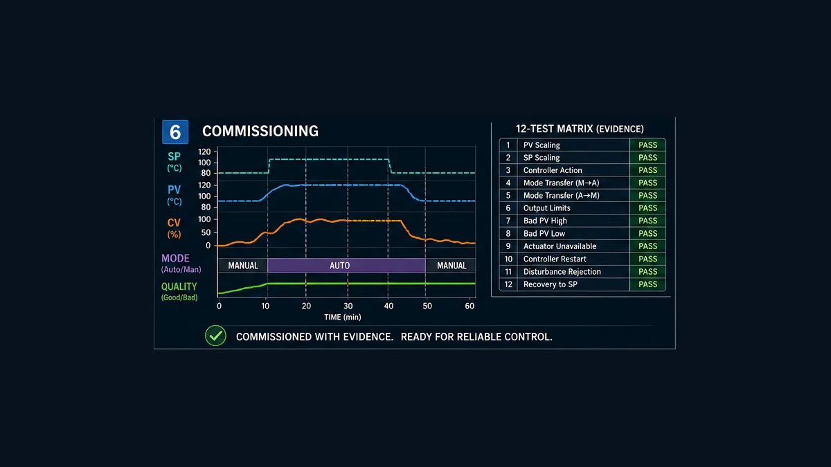
Minimum trend set
Capture SP request and effective SP; PV value, quality and age; raw, limited and applied CV; manual value; requested and effective mode; Program/Operator ownership where used; high/low-limit state; actuator availability and feedback; initialization/tracking state; timing/fault status; and relevant disturbance variables. Use a shared time basis and sufficient sample rate to see the fastest expected transition.
Before a controller download or online edit, establish authorization, backup, compare, impact assessment, communication path, rollback method and safe process state. After the change, verify the controller revision and actual running logic, clear any temporary forces or test substitutions through the approved procedure, repeat critical regressions and archive the as-left project with evidence.
RSLogix 5000 PID troubleshooting sequence
When a loop does not control, do not begin with Kp. Work from truth at the physical boundary toward the calculation:
| Order | Question | Decisive evidence |
|---|---|---|
| 1 | is this the intended online controller and project revision? | communications path, controller identity and verified project compare |
| 2 | is the physical measurement credible? | independent process reference and transmitter/module diagnostics |
| 3 | are raw and engineering-unit values scaled correctly? | low/mid/high source records |
| 4 | is PV current and good? | fault, timestamp, age and substitution/force status |
| 5 | what is the effective SP and who owns it? | request, bound/rate logic, mode and source |
| 6 | is the instruction executing with the intended delta time? | task and timing-mode evidence |
| 7 | what does the controller request? | raw CV, error and instruction status |
| 8 | what constraint changes that request? | limit, selector, interlock and equipment availability |
| 9 | what output is actually applied? | output tag/module state and command path |
| 10 | did the final element move? | position/speed/current feedback and field observation |
| 11 | did the process respond in the expected direction and delay? | synchronized CV-feedback-PV trend |
| 12 | does the resulting response violate agreed criteria? | numerical comparison with approved acceptance thresholds |
This order prevents a common maintenance failure: making the controller more aggressive while a valve is stuck, a PV is stale, a task is misconfigured or an output is saturated. The simulator can help technicians rehearse this evidence chain, but it cannot validate a live loop model or authorize a plant change.
Frequently asked questions
Is RSLogix 5000 PID the same as Studio 5000 PID?
The search phrases usually refer to the same Logix-controller engineering lineage, but current Rockwell documentation uses Studio 5000 Logix Designer. Always record the exact software version, controller and firmware; the product name alone is not a compatibility specification.
What is the difference between PID and PIDE in Studio 5000?
PID is the classic instruction documented for Ladder and Structured Text. PIDE is the enhanced process-control instruction documented for Function Block and Structured Text, with a broader mode, initialization, cascade, windup and engineering-unit interface. Select from verified project requirements and installed support, not from the “enhanced” label alone.
Should I use PID, PIDE or PlantPAx PPID?
Retain or use PID when it is the validated project standard and meets the requirement. Use PIDE when its enhanced interface and supported routine/timing architecture fit. Use PPID when a compatible PlantPAx project and library lifecycle require the integrated process object. Migration cost, HMI conventions, team support and regression evidence are part of the decision.
Does PIDE need a periodic task?
Rockwell’s official example says the easiest PIDE implementation is a function-block routine in a periodic task and that periodic timing mode uses the task update rate as delta time. PIDE also documents other timing modes. Follow the exact revision’s requirements and verify measured execution; do not infer that any task period is suitable.
What task period should a ControlLogix PID use?
There is no universal period. Choose it from sensor/input update, process delay and time constants, output/actuator response, desired control bandwidth, controller loading and the instruction’s supported timing model. A 500 ms thermal-loop example is not a recommendation for pressure, motion or another loop.
How do I call PIDE in Structured Text?
Rockwell’s documented pattern assigns input members to a PIDE tag, executes PIDE(PIDE_tag);, then uses the relevant output member. Member names and support must match the installed version. Put scaling, quality, modes, constraints and equipment ownership around that call rather than treating four lines as a production module.
Why does my Studio 5000 PID output switch between 0 and 100 percent?
Possible causes include aggressive gain, wrong PV/CV scaling, an output mapped to a discrete or integer surface, high/low limits, actuator stiction, noisy measurement, timing mismatch or a process with insufficient authority. Trend raw, limited and applied CV plus actuator feedback and PV before changing tuning.
How do I make manual-to-auto transfer bumpless?
Align controller state with the demand actually applied before Auto takes ownership. Classic PID documents tieback/manual behavior; PIDE documents CV initialization surfaces. Define a numerical bump tolerance and test the transition at the applied output, including cases where a downstream selector or constraint changes the raw PID request.
Does output limiting automatically prevent integral windup?
Rockwell documents anti-reset windup for classic PID limits and windup coordination for PIDE, but external limits or unavailable equipment may be invisible to the instruction. Keep requested, limited and applied outputs separate, connect the supported tracking/windup mechanism and prove saturation recovery.
Can I copy PID gains from another PLC or another Rockwell instruction?
Not safely by label alone. Equation form, gain units, PV/CV span, task interval, proportional/derivative basis, filters and process dynamics can differ. Convert only with verified formulas and validate under an approved process-specific commissioning plan.
Can PIDE autotune the loop automatically?
Rockwell documents a built-in open-loop PIDE autotuner with activation and programming-language support conditions. Open-loop excitation can move a real process toward unsafe conditions. Verify product support and use it only under an approved, risk-controlled procedure with qualified personnel and independent protection.
What should I trend for PID troubleshooting?
Trend SP request/effective SP, PV value/quality/age, raw/limited/applied CV, mode request/effective mode, ownership, initialization/tracking, limit status, actuator availability/feedback, timing/fault status and relevant disturbances on a synchronized time base.
Should interlocks be programmed inside the PID instruction?
The PID regulates; equipment permissives, interlocks and independent safety functions have separate ownership. Coordinate their effect on applied output and controller tracking so recovery is predictable, but do not hide protection in tuning parameters or treat ordinary PLC logic as an unverified safety function.
Can a simulator provide the correct final tuning values?
Only a validated model used inside an approved engineering workflow can support field-specific conclusions. A learning simulator can teach action, timing, saturation, modes and evidence collection, but it cannot reproduce unmeasured valve stiction, exchanger fouling, sensor placement, utility limits, nonlinearities or hazards.
Sources, review scope and limitations
This guide was reviewed on August 31, 2026. Official documentation, software, firmware and process libraries change. Verify the installed controller, firmware, Studio 5000 version, exact instruction help and current project standards before implementation.
- Proportional Integral Derivative (PID), Studio 5000 Logix Designer 38.01 — Rockwell Automation
- Using PID instructions — Rockwell Automation
- PID instruction timing — Rockwell Automation
- Anti-reset windup and bumpless transfer from manual to auto for PID — Rockwell Automation
- Bumpless restart for PID — Rockwell Automation
- Using output limiting for PID — Rockwell Automation
- Enhanced PID (PIDE), Studio 5000 Logix Designer 37 — Rockwell Automation
- Function-block timing modes — Rockwell Automation
- Tasks, programs and routines — Rockwell Automation
- PlantPAx PPID instruction, Studio 5000 Logix Designer 38.01 — Rockwell Automation
- Logix 5000 Controllers Design Considerations reference manual — Rockwell Automation
- Logix 5000 Controllers Tasks, Programs, and Routines programming manual — Rockwell Automation
- NIST SP 800-82 Rev. 3, Guide to Operational Technology Security — NIST
- 29 CFR 1910.147, control of hazardous energy — OSHA
- Recommended Practices for Safety and Health Programs — OSHA
The loop, tag contract, numerical teaching values, diagnostic tables, acceptance matrix and six generated illustrations are original editorial material. The illustrations are conceptual and do not reproduce the Studio 5000 interface, controller code, wiring, a P&ID or a safety architecture.
This page does not authorize connecting, downloading, editing online, forcing, bypassing, tuning, energizing, operating or testing installed equipment. Qualified and authorized personnel must apply the site hazard assessment, hazardous-energy and electrical safe-work requirements, process limits, independent protection, cybersecurity controls, manufacturer instructions, backups, management of change, commissioning plan and rollback procedure.
Now run it · free to start
Tune a PID loop against a live process model
Change the setpoint and loop terms, then measure overshoot, settling time and error in a browser PID lab. Free to start, nothing to install.
Ownership disclosure: PLC Programming IO and PLC Simulation Software are operated by the same publisher.
PLC Programming IO Editorial Team
Industrial automation education, references, and software testing
The PLC Programming IO Editorial Team publishes sourced industrial-automation education and documents how material is reviewed, tested, and corrected. A team byline means the publisher is responsible for the page; it does not represent a fictional person or imply an engineering licence.
Coverage:
- • PLC programming concepts and examples
- • Vendor software tutorials and comparisons
- • SCADA, HMI, protocols, and instrumentation
- • Training, careers, and reference material
Review standard:
- • Prefer primary and official sources
- • Record software versions when material
- • Separate tested facts from estimates
- • Publish material corrections
Important scope note
This site provides education, not project-specific engineering approval. Safety, code, and compliance decisions require a qualified person with access to the actual machine and jurisdiction.