FX5U PID in GX Works3: Instruction, Tuning and Example
Implement Mitsubishi FX5U PID control with the correct instruction-versus-parameter path, protected operand range, engineering-unit scaling, deterministic sampling, Manual/Auto wrapper, bounded autotuning and commissioning evidence.
Review status: Editorially reviewed against Mitsubishi MELSEC iQ-F FX5 User's Manual (Application) JY997D55401AF dated October 2025, current iQ-F instruction/training documentation, FX5 temperature-control-module documentation and current Mitsubishi FAQs for FX5 CPU autotuning, control-response and GX Works3 instruction guidance; the oven model and figures are original teaching examples, while exact CPU, firmware, software, devices/labels, module representation, output hardware, process limits, tuning values and safety protections require project-specific verification
Direct answer
An FX5U PID loop can be implemented in two CPU-owned ways documented in the current Mitsubishi Application manual: PID control via the PID instruction or PID control via GX Works3 CPU parameters. A compatible FX5 temperature-control module can also own PID, which is a third architecture. Pick one owner. Do not run an instruction loop and a parameter/module loop against the same heater.
For the instruction route, Mitsubishi documents the Ladder/FBD operand shape as PID (s1) (s2) (s3) (d) and Structured Text form as ENO := PID(EN, s1, s2, s3, d);. s1 stores target value (SV), s2 stores measured/process value (PV), s3 is the head of the PID parameter range, and d stores manipulated/output value (MV). The current application manual describes signed 16-bit SV, PV and MV values. It requires 25 devices from s3 for normal control, with mode-dependent autotune ranges up to 29 devices. Words s3+7 through s3+19 are reserved for internal processing and must not be changed.
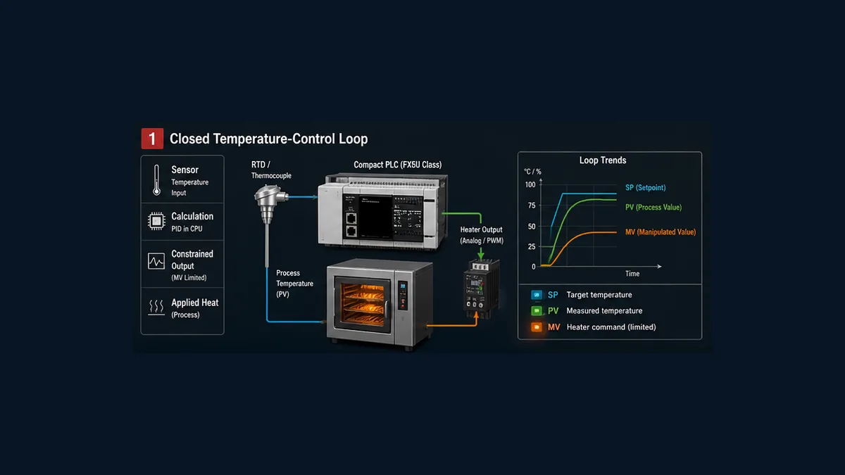
A maintainable loop still needs more than the instruction: a qualified engineering-unit PV, bounded SV, protected configuration owner, proven direction, measured timing, requested/limited/applied MV, explicit Manual/Auto transition, heater availability, invalid-PV response, autotune authorization and synchronized evidence. The worked oven uses 0.1 °C PV/SV units and 0.1% MV units, but it deliberately supplies no universal gains.
Download the FX5U PID loop design register, 18-test acceptance matrix and symbolic GX Works3 program outline to map the design into the exact project.
Choose one FX5 PID architecture
The current FX5 Application manual separates CPU PID via instruction from CPU PID via parameter. Mitsubishi also publishes a separate FX5 temperature-control-module manual with its own standard and heating/cooling PID functions. They solve overlapping tasks through different ownership surfaces.
| Architecture | Where configuration lives | Program role | Strong fit | Main risk |
|---|---|---|---|---|
| CPU PID instruction | protected devices/labels beginning at s3, initialized by reviewed logic/configuration |
qualify SV/PV, execute PID, handle modes/constraints/output |
custom wrapper, explicit state/evidence, existing instruction standards | parameter-range overlap, unsafe copied devices, missing mode/quality design |
| CPU PID via parameter | GX Works3 CPU Parameter → PID Control Setting, with mapped values/commands/status | map signals and supervise configured function | standard or heating/cooling loops that fit the built-in parameter workflow | hidden ownership or unreviewed online parameter/device changes |
| FX5 temperature-control module | module parameters/buffer or labels according to exact module manual | configure/supervise module and consume status | multichannel temperature control and module-specific features | treating module parameters as CPU s3 words or running a second CPU loop |
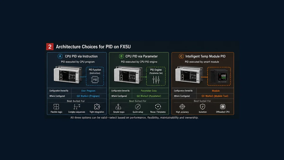
The parameter route is more than a GUI version of one instruction call. Mitsubishi documents standard PID and heating-cooling modes, two-position/P/PI/PD/PID choices, output cycles, autotuning, errors, limits, output change-rate limiting in applicable modes, temperature-rise completion and Normal/Fast control response. The instruction route exposes a specific device layout and equation. Preserve that distinction in the project architecture.
This page implements the instruction route deeply and compares the parameter path where the behavior changes. Use the vendor-neutral PID program guide for platform-independent design and the Mitsubishi FX5U first-program guide for request/feedback logic outside process control.
Freeze the FX5 compatibility and unit manifest
Record the exact CPU model, firmware, GX Works3 release, input/output modules or adapters, program language, labels/devices and controlled manual revisions. The current manual revision used here is JY997D55401AF, created in October 2025. Future or older revisions may differ.
| Compatibility surface | Record | Why it changes the answer |
|---|---|---|
| CPU | FX5U/FX5UC/FX5UJ/FX5S exact model and firmware | supported functions, built-in analog and device capacity differ |
| GX Works3 | version/update and project compatibility | parameter UI, target support, compile and download behavior change |
| implementation path | instruction, CPU parameter or module PID | defines the authoritative parameter/status model |
| input source | built-in analog, adapter, intelligent module or network value | units, conversion time, fault/status and freshness differ |
| output | analog, drive setpoint, transistor time-proportioning or module output | scaling, update cycle, hardware rating and fallback differ |
| numeric units | e.g. 0.1 °C and 0.1% | the instruction sees integers, not meaning |
| device/label map | every SV, PV, parameter, MV and status location | protects against overlap and unowned HMI/recipe writes |
| execution | program/task/scan and instruction enable pattern | sampling time cannot be shorter than the relevant operation cycle |
| protections | independent trips/interlocks and hazardous-energy design | ordinary PID is not a safety function |
Mitsubishi’s current FAQ says GX Works3 instruction help can be opened with F1 or the context menu. Use that installed help together with the controlled manuals; do not resolve a compile error by swapping operands until the editor accepts something.
Worked FX5U oven contract
The teaching loop is TIC-501, an electric oven with a qualified temperature input and approved heater output stage.
| Item | Teaching design | Production source |
|---|---|---|
| PV engineering range | 20.0–180.0 °C | sensor, module and calibrated process range |
| internal PV/SV representation | 200–1800 in 0.1 °C units | signed numeric contract and module conversion |
| normal SV | 800 = 80.0 °C | recipe and process owner |
| permitted SV range | 200–1200 = 20.0–120.0 °C | approved equipment/product envelope |
| MV representation | 0–1000 = 0.0–100.0% | output contract |
| teaching sampling time | 500 ms | measured timing and process dynamics |
| teaching output window | 8 seconds | final-element design; not a recommendation |
| initial operating mode | Manual | commissioning method |
| action statement | increasing applied heater demand should raise PV after delay | authorized manual step test |
Separate regulation from protection. A high-high temperature limit, heater contactor monitoring, airflow proving, fire protection or other risk reduction follows the applicable design and proof-test lifecycle. A CPU PID call must not be the only barrier against hazardous overheating.
Qualify and scale PV before PID
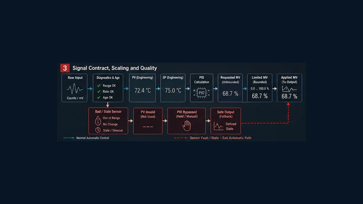
Mitsubishi’s application manual states that normal measurement data must be read before PID operation and specifically cautions about analog-input conversion time. Treat the source as value plus quality plus age.
For a generic input-scale teaching assumption, suppose the verified source is 0–4000 raw counts for 20.0–180.0 °C. To produce 0.1 °C units:
PV_tenths = 200 + Raw × (1800 - 200) / 4000
| Raw | Calculation | Expected internal PV | Engineering PV |
|---|---|---|---|
| 0 | 200 + 0 × 1600 / 4000 |
200 | 20.0 °C |
| 1000 | 200 + 1000 × 1600 / 4000 |
600 | 60.0 °C |
| 2000 | 200 + 2000 × 1600 / 4000 |
1000 | 100.0 °C |
| 3000 | 200 + 3000 × 1600 / 4000 |
1400 | 140.0 °C |
| 4000 | 200 + 4000 × 1600 / 4000 |
1800 | 180.0 °C |
The raw range is hypothetical. An FX5 thermocouple adapter may already expose temperature in a documented scaled representation. Do not scale twice. Prove low, midpoint and high points and preserve adequate arithmetic width/order.
Define bad PV as more than out-of-range: module/electrical error, over/under-range, stale age, unexpected no-change, forced/substituted value and violated plausibility. On bad PV, reject or leave normal Auto and apply the approved fallback. An autotune also needs a no-change watchdog; Mitsubishi warns that autotuning may never finish if PV does not change due to a broken analog path.
Live mini-lab
Try it: press START, then STOP
A stop-dominant seal-in rung: START latches the motor output through its own contact, and STOP breaks the circuit.
Watch the output lamp: it stays on after START until you press STOP.
Free to start · runs in your browserOpens plcsimulationsoftware.com — same team
Map the FX5 PID instruction exactly
The current application manual provides this operand contract:
| Operand | Current documented role | Teaching mapping | Critical boundary |
|---|---|---|---|
s1 |
target value SV, signed 16-bit | TIC501_SV in 0.1 °C |
range and units must match PV |
s2 |
measured value PV, signed 16-bit | TIC501_PV in 0.1 °C |
read current normal measurement first |
s3 |
head device storing PID parameters | TIC501_PID_BASE |
reserve complete mode-dependent device range |
d |
output value MV, signed 16-bit | TIC501_MV_REQUEST in 0.1% |
initialize before first drive and constrain before output |
EN/ENO |
execution condition/result in ST/FBD | wrapper execution/status | not a Manual/Auto/tieback interface by itself |
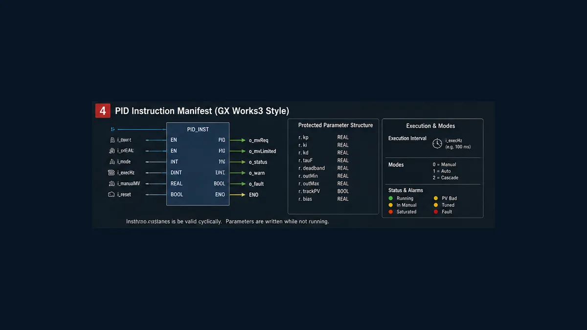
If labels are used as operands, the application manual says to use global labels assigned to devices. Preserve the device assignment in change control; a label name alone does not reserve the adjoining parameter words.
Reserve the whole s3 range
| Selected function | Current documented occupied range |
|---|---|
| normal PID | 25 devices from s3 |
| limit-cycle autotune | 29 devices from s3 |
| step-response autotune without hunting suppression | 25 devices from s3 |
| step-response autotune with hunting suppression | 28 devices from s3 |
Cross-reference direct and indirect instructions, HMI writes, recipes, data moves, initializers and other blocks over the largest selected range. Words s3+7 through s3+19 belong to internal PID processing in the current manual; do not initialize, display as editable tuning fields or reuse them.
Review the visible parameter surface
| Offset | Current manual meaning | Unit/range note |
|---|---|---|
s3 |
sampling time TS |
1–32767 ms; cannot be shorter than PLC operation cycle |
s3+1 |
operation setting ACT |
direction, alarms, autotune, output limits and tuning-method bits |
s3+2 |
input filter coefficient | 0–99%; zero disables input filter |
s3+3 |
proportional gain KP |
percent representation per manual |
s3+4 |
integral time TI |
×100 ms; zero means no integration |
s3+5 |
differential gain KD |
percent; zero removes differential-gain contribution |
s3+6 |
differential time TD |
×10 ms; zero means no differential action |
s3+20/+21 |
input variation alarm thresholds | applicable when enabled |
s3+22/+23 |
output variation alarms or upper/lower limits | meaning depends on ACT settings; incompatible bits are documented |
s3+24 |
alarm-output bits | expose and trend applicable conditions |
s3+25…+28 |
method-dependent autotune data | reserve only according to exact selected method, but never overlap |
Do not copy the manual’s sample KP, TI or TD values as initial production tuning. They demonstrate representation, not your oven dynamics.
Execute with a defensible sampling time
The instruction calculates a new MV at each configured sampling time while the program executes the instruction in the documented pattern. TS must not be shorter than the PLC’s operation cycle. The parameter-driven path similarly requires its sampling time to exceed scan time and be smaller than the control-output cycle in the documented example.
Measure the entire chain:
| Timing surface | Evidence |
|---|---|
| sensor/transmitter | response and damping/filter setting |
| analog/temperature module | conversion time, update and fault status |
| program | measured scan/task behavior under peak representative load |
| PID | configured TS, actual MV update markers and enable pattern |
| output | analog update or time-proportioning window phase |
| heater/process | dead time, time constant and response across operating range |
A 10 ms TS does not create meaningful 10 ms temperature information from a slow thermocouple and filtered module. A 500 ms teaching sample may be conservative for a slow oven but could be wrong for another loop. Choose a stable supported interval from measured dynamics and signal freshness.
Build Manual, Auto and applied-MV tracking around the instruction
The four-operand PID signature does not expose a generic Manual/Auto or tieback operand. Do not invent one. Build an explicit wrapper and use only target-documented methods to initialize/controller state.
| Surface | Meaning | Keep observable |
|---|---|---|
| mode request | operator/sequence asks for Manual or Auto | requester and timestamp |
| mode effective | wrapper has accepted a mode given current permissives | Manual/Auto/blocked plus reason |
| MV request | result in d from PID |
unconstrained controller demand |
| MV limited | demand after high/low/rate/state constraints | active constraint and reason |
| MV applied | demand after Manual/Auto selection, heater availability and final output logic | actual normal-control request to hardware |
Automatic can require valid current PV, valid configuration checksum/revision, bounded SV, heater available, no blocking fault and a tested state. Manual-to-Auto should not jump from a 37% applied output to an unrelated retained MV. Define how the instruction’s initial d and internal words are established using the current manual and prove the transfer on a safe target. If the exact instruction cannot meet the project’s tracking requirement cleanly, choose the parameter/module architecture or a reviewed wrapper/library rather than hiding a bump.
Never continue integrating invisibly while downstream logic holds the heater at zero unless the target-supported design prevents or handles resulting windup. Trend requested and applied MV so the constraint is visible.
Convert MV to an approved output
For an analog output, convert the declared 0.1% MV representation through one reviewed scale and prove low/mid/high physical output. For a time-proportioned heater, use a separately designed window and appropriate switching device.
In an original 8-second teaching window, 37.5% applied MV gives:
On_time = 8 s × 37.5 / 100 = 3.0 s
This is not a relay/SSR recommendation. The electrical designer must approve switching technology, current, heat sinking, minimum pulse, cycle rate, failure detection, protection and de-energized state. A standard output bit is not a safety-rated heater shutdown merely because the program sets it off.
The current Application manual’s parameter-driven example illustrates the same duty-cycle concept using its own configured control-output cycle. Its example values are explanatory, not a universal cycle for every heater.
Treat FX5U autotuning as a controlled process test
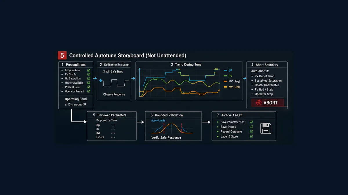
Mitsubishi documents step-response and limit-cycle autotuning for the instruction path. Current FX5 FAQs also confirm that autotuning can be switched for supported FX5 CPU families. Autotune deliberately excites the process; it is not a harmless software calculation.
Step-response method
The current manual describes applying a step output and deriving constants from maximum ramp and dead time. It notes that the user sets the step output in d, and the PID instruction does not change MV during this autotune method. The selected step must be safe for the real process. A high percentage on an electric heater can exceed product/equipment limits before the slow sensor shows the full response.
Limit-cycle method
The current manual describes upper/lower MV values and PV hysteresis settings. During this method, the instruction alternates the applicable output limits to excite the process, then stores calculated KP, TI and TD. The full 29-word range must be reserved.
Preconditions, aborts and review
| Before | During | After |
|---|---|---|
| exact CPU/manual/method confirmed | SV, PV and all MV surfaces trend | generated parameters range-reviewed |
| input/output scaling and direction proved | independent protections remain active | old parameter set retained for rollback |
| process stable in approved band | abort on invalid/no-change PV, timeout or process bound | bounded response test run before production |
| safe step/limits/hysteresis signed | heater availability and saturation visible | program/parameters/checksum archived |
| staffing and product/equipment consequences accepted | operator stop path tested | deviations and as-left evidence signed |
Mitsubishi warns that step-response autotune should start with a stable system and that PV no-change from a broken input can prevent completion. Build watchdog logic outside the optimistic path. Do not rely only on an autotune bit eventually turning off.
Understand the GX Works3 parameter-driven PID path
The current manual’s path begins at CPU Parameter → PID Control Setting → Heating/Cooling PID Control Setting. It describes configuration, program mapping, parameter write, a STOP-to-RUN transition and execution command. That lifecycle matters for change control; a parameter edit is not necessarily equivalent to an ordinary data write.
The parameter path can map SV, PV, MV, control output, execution command/status, autotune command/status and error code. It also supports standard versus heating/cooling control and an output cycle. Current Mitsubishi FAQ explains the Normal/Fast response selection: Normal takes longer but suppresses over/undershoot; Fast reaches target sooner with more over/undershoot. That is a behavior choice, not a better/worse label.
Use the parameter path when its exposed function and lifecycle fit the loop. Still add value quality, requested/effective modes, heater availability, independent protection, synchronized evidence and signed tests around it.
Commission and troubleshoot in evidence order
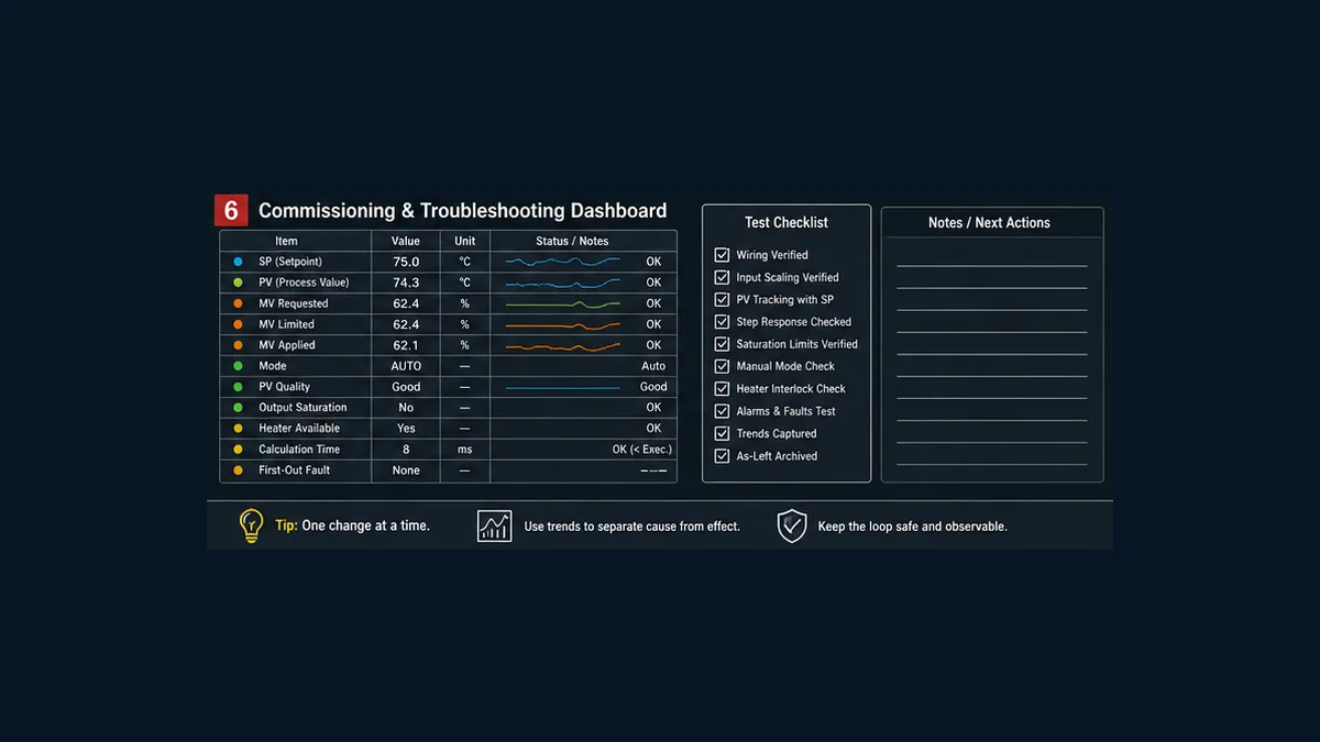
- Freeze the target, software, implementation path and manuals.
- Review process hazards and independent protection.
- Protect the full device/label range and prove every writer.
- Three-point-check the measurement and quality states.
- Prove the final output in Manual at approved low/mid/high points.
- Prove process direction with a bounded manual step.
- Measure scan, input freshness, PID update, output cycle and process delay.
- Test Manual/Auto acceptance and both transfers.
- Inject bad/stale/no-change PV, heater unavailable, limits and restart.
- Load conservative approved initial parameters or run an authorized autotune.
- Test separate SV change and disturbance response across the operating region.
- Archive program, GX Works3/CPU parameters, device map, tuning, trends and deviations.
Symptom-to-evidence matrix
| Symptom | Compare first | Likely boundary | Avoid first |
|---|---|---|---|
PID appears not to update |
EN/call path, TS, scan, current PV, operand/device support and instruction error | execution or target mapping | changing gains |
| MV changes but heater does not | requested/limited/applied MV, mode, availability, output and field feedback | downstream constraint/output | autotuning |
| PV moves away from SV | applied MV step, PV direction, ACT action and signal inversions | action/wiring/process direction | larger integral |
| output is fixed at upper limit | SV/PV units, saturation, applied output, heater capacity and process losses | scale, availability or insufficient capacity | removing limits |
| oscillation | TS/update evidence, PV noise/filter, output window, MV limits and gains | timing/noise/profile/tuning | switching to Fast response blindly |
| long recovery after constraint | requested versus applied MV and internal-state behavior | windup/tracking/availability | hiding applied MV from trend |
| values change after restart | initialization order, latch settings, HMI/recipe and full s3 writers |
retention/ownership | random online edits |
| autotune never ends | PV change/quality, method flags, timeout, output application and process response | failed precondition/sensor/output | waiting unattended |
| autotune completes but response is poor | exact method, generated constants, operating point, limits and validation trend | model mismatch/nonlinearity/constraints | immediate production release |
| parameter path differs from instruction example | selected owner and exact configuration lifecycle | architecture mismatch | copying s3 offsets into parameter mode |
Trend SV, PV, requested/limited/applied MV, requested/effective mode, PV quality/age, saturation, heater availability, sample/update markers, autotune status, PID error/status code and first-out event on one time base.
Frequently asked questions
What is the FX5U PID instruction syntax?
The current Mitsubishi application manual shows Ladder/FBD PID (s1) (s2) (s3) (d) and Structured Text ENO := PID(EN, s1, s2, s3, d);. The operands are SV, PV, parameter-range head and MV. Verify target support and exact device/label rules in the installed GX Works3 help and current instruction manual.
How many devices does FX5U PID occupy from s3?
The current application manual states 25 devices for normal PID, 29 for limit-cycle autotune, 25 for step-response autotune without hunting suppression and 28 with it. Reserve the largest range used and do not modify internal words s3+7 through s3+19.
Can I use labels with the FX5 PID instruction?
Yes, within the documented operand rules. The current manual notes that labels used for these operands must be global labels assigned to devices. The adjoining s3 range still needs explicit reservation and cross-reference.
What sampling time should I use for FX5U PID?
There is no universal value. The instruction manual requires TS not to be shorter than the PLC operation cycle. Select it from sensor/module update, measured scan, process dynamics and noise, then prove actual MV updates under representative load.
What is forward versus backward operation in FX5 PID?
It determines the deviation sign used by the instruction. The correct setting comes from a written process-direction statement and an authorized manual output step. For a simple heater, more output normally raises PV, but wiring and output inversions must still be proved.
How do I scale temperature for FX5U PID?
Choose one signed integer unit contract—such as 0.1 °C—then convert the exact module representation once and prove low/mid/high points. SV and PV must use the same units. Do not reuse the article’s hypothetical 0–4000 raw range without verifying the actual module.
What is the difference between FX5 PID via instruction and via parameter?
Instruction mode stores parameters in a protected device range and uses an explicit PID call. Parameter mode is configured under GX Works3 CPU PID settings and exposes standard/heating-cooling features and mapped commands/status. Choose one owner based on project requirements and lifecycle.
Can an FX5 temperature module run PID itself?
Applicable FX5 temperature-control modules have their own documented PID functions. If the module owns control, configure and supervise that architecture; do not also run an unrelated CPU PID on the same output.
How do I make FX5U PID Manual-to-Auto transfer bumpless?
The four-operand instruction has no generic tieback input, so build an explicit mode wrapper and use target-documented initialization/state handling. Track requested, limited and applied MV, accept Auto only when conditions are valid, and prove the output step against a signed criterion.
How do I limit FX5U PID output?
The instruction’s ACT settings can enable documented upper/lower MV limits at s3+22 and s3+23; verify the exact bit combination because those words can have other alarm meanings. Also expose any downstream constraint and applied MV instead of hiding it.
How does FX5U PID autotuning work?
The instruction route documents step-response and limit-cycle methods. Both intentionally excite the process and require correct flags, ranges and safe output settings. Use a supervised state sequence with preconditions, no-change/timeout/process-bound aborts, parameter review and bounded validation.
Why does FX5U PID autotuning never finish?
Check PV validity and change, actual heater output, method/flag settings, sample time, limits and process response. Mitsubishi explicitly warns that PV may not change due to an analog wire break and recommends monitoring PV or elapsed tuning time.
What does Normal versus Fast response mean in FX5 parameter PID?
Mitsubishi’s current FAQ says Normal takes longer to reach SV while suppressing over/undershoot; Fast reaches SV sooner with more over/undershoot. Select from signed process criteria and validate across the operating region.
Is this FX5U PID example ready for a production heater?
No. It is technical teaching content and symbolic documentation. Production requires exact target mapping, input/output engineering, process and electrical design, independent protection, authorized tuning and signed acceptance evidence.
Primary sources and further reading
- MELSEC iQ-F FX5 User's Manual (Application), JY997D55401AF
- MELSEC iQ-F manuals download page
- MELSEC iQ-F basic course for GX Works3
- MELSEC iQ-F FX5 temperature-control-module manual
- MELSEC iQ-F series product page
- Mitsubishi iQ-F advanced functions
- Mitsubishi FAQ: switching FX5 PID autotuning
- Mitsubishi FAQ: built-in PID Normal versus Fast response
- Mitsubishi FAQ: GX Works3 guidance flow
- Mitsubishi FAQ: GX Works3 instruction help
- Mitsubishi FAQ: iQ-F integer-to-floating-point instructions
- IEC 61131-3 programmable-controller languages
- ISA: PID controller fundamentals
- NIST/SEMATECH: process modeling
- OSHA control of hazardous energy
- OSHA machine guarding
Treat the exact installed Mitsubishi manual and controlled project as the specification. Tutorials, forum examples and screenshots can suggest questions; they cannot establish device ownership, tuning, field output behavior or protection requirements.
Now run it · free to start
Tune a PID loop against a live process model
Change the setpoint and loop terms, then measure overshoot, settling time and error in a browser PID lab. Free to start, nothing to install.
Ownership disclosure: PLC Programming IO and PLC Simulation Software are operated by the same publisher.
PLC Programming IO Editorial Team
Industrial automation education, references, and software testing
The PLC Programming IO Editorial Team publishes sourced industrial-automation education and documents how material is reviewed, tested, and corrected. A team byline means the publisher is responsible for the page; it does not represent a fictional person or imply an engineering licence.
Coverage:
- • PLC programming concepts and examples
- • Vendor software tutorials and comparisons
- • SCADA, HMI, protocols, and instrumentation
- • Training, careers, and reference material
Review standard:
- • Prefer primary and official sources
- • Record software versions when material
- • Separate tested facts from estimates
- • Publish material corrections
Important scope note
This site provides education, not project-specific engineering approval. Safety, code, and compliance decisions require a qualified person with access to the actual machine and jurisdiction.