Advanced Process Control: MPC, APC Layers and Examples
Understand advanced process control from cascade and inferentials through constrained MPC, commissioning, software selection, operator handoff and sustained benefits.
Review status: Editorially reviewed against the ISA advanced-process-control overview and Automation Body of Knowledge scope; Qin and Badgwell's MPC survey and recent peer-reviewed MPC application literature; current official Honeywell, AspenTech, AVEVA, KBC, ABB, Emerson and MathWorks capability pages; NIST SP 800-82 Rev. 3; and US OSHA process-safety-management and hazardous-energy rules. Product capabilities, models, constraints, economic objectives, control authority, tuning, safety functions, cybersecurity controls, licensing, integrations, benefit estimates and acceptance limits remain process-, site-, version-, vendor- and risk-specific
Direct answer
Advanced process control (APC) is the layer of control methods used when well-tuned individual regulatory loops are not enough to keep a process near its best operating region. The term is an umbrella, not one algorithm. It can include cascade, ratio, feedforward, override/selective control, inferential measurements, decoupling, multivariable model predictive control (MPC) and a controlled interface to real-time optimization. A useful APC system coordinates variables, predicts interactions or disturbances, respects operating constraints and returns authority cleanly to the plant's base control system when its prerequisites fail.
APC does not replace instruments, valves, PID loops, interlocks, alarms, a basic process control system (BPCS) or a safety instrumented system (SIS). It depends on those layers. A model cannot repair a sticking valve, a biased analyzer, wrong engineering units or a PID loop left in manual. The first APC decision is therefore a readiness decision: prove measurement quality, final-element response, regulatory-loop stability, material/energy balances, operating modes, constraints, operator ownership and safe fallback before estimating the benefit of a sophisticated controller.
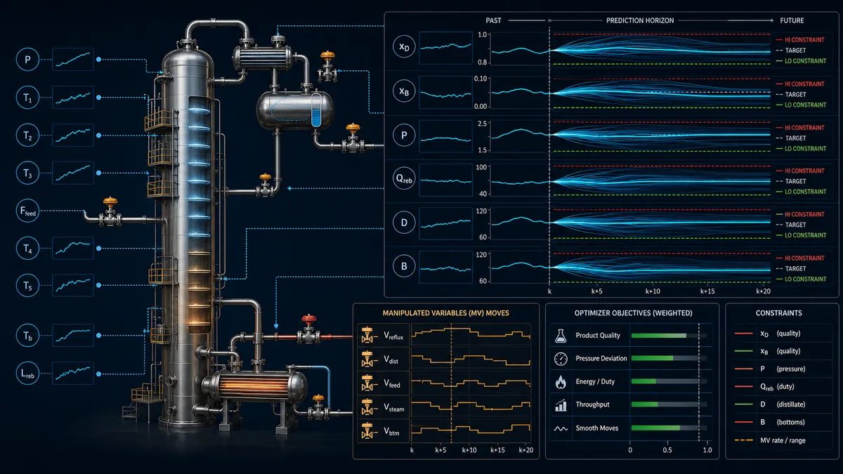
MPC is the best-known APC method because it handles interacting variables and explicit constraints in one repeated calculation. At each execution, an MPC controller uses a dynamic model and current measurements to predict future controlled variables (CVs). It selects a sequence of manipulated-variable (MV) moves that reduces objective error while honoring MV, move-rate and CV constraints. Only the first move is applied; the calculation repeats after new measurements arrive. Disturbance variables (DVs) can improve prediction when their future or current effect is measurable.
A credible project is judged by more than whether the APC status says “on.” It must show that the base loops remain healthy, the intended CVs and MVs are eligible, constraints are correctly prioritized, moves are bounded, operator transitions are understandable, fallback is bumpless, and normalized economic or operating evidence persists after commissioning. Software is only one component of that lifecycle.

Separate the process-control layers before selecting APC
Keep field, regulatory, supervisory and safety responsibilities explicit
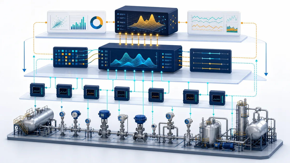
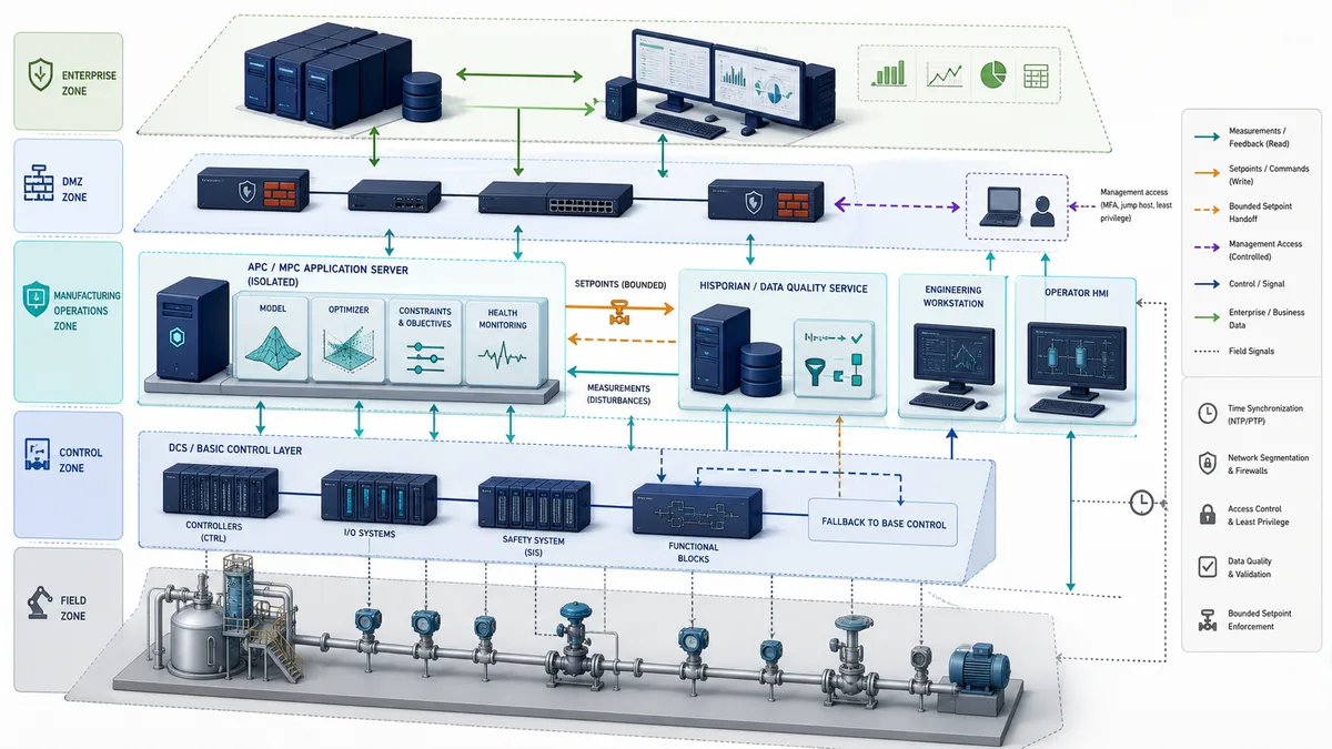
The cleanest architecture begins at the physical process. Instruments measure it; valves, drives and other final elements influence it. Regulatory PID loops reject ordinary disturbances and keep individual variables stable. Advanced regulatory strategies coordinate a small number of loops. MPC coordinates several interacting variables over a prediction horizon. A real-time optimizer may periodically calculate economically preferred targets that remain inside an approved feasible envelope.
Interlocks, permissives, alarms and SIS functions retain their own authorities. They must not depend on an APC solver remaining available. If an APC application writes a setpoint or output target, the receiving BPCS logic must still enforce engineering limits, rate limits, mode eligibility and the approved response to invalid or stale data.
| Layer | Primary job | Typical inputs and outputs | Evidence required before APC relies on it | Authority boundary |
|---|---|---|---|---|
| Physical process | Convert material and energy | Flows, compositions, pressure, temperature, inventory | Operating envelope, dynamics and hazards understood | Governed by physics and equipment limits |
| Instrument/final element | Measure or influence the process | Transmitter values, analyzer results, valve/drive commands | Calibration, range, quality, response, fail behavior | Device and process design limits |
| BPCS regulatory control | Stabilize individual loops and sequences | PID PV/SP/OUT, modes, interlocks | Loop performance, scaling, anti-windup, modes and fallback | Executes normal control within engineered limits |
| Advanced regulatory control | Coordinate a few related loops | Cascade, ratio, feedforward, selectors | Interaction and disturbance path proven | Supervisory setpoints or bounded outputs |
| Inferential/soft sensor | Estimate a hard-to-measure property | Multiple measurements to estimated quality | Reference lab/analyzer reconciliation and uncertainty | Advisory or controlled use with quality gate |
| MPC | Coordinate multiple interacting variables and constraints | CVs, MVs, DVs, model, limits and priorities | Model validation and closed-loop eligibility | Bounded supervisory moves; BPCS remains able to recover |
| Real-time optimization | Calculate economic targets | Prices, yields, equipment and model constraints | Objective ownership, data reconciliation and feasibility | Supplies targets; must not bypass lower-layer constraints |
| SIS/protection | Reduce risk when hazardous conditions demand action | Safety inputs, logic solver and final elements | Independent safety lifecycle evidence | Never substituted by ordinary APC availability |
Distinguish APC from ordinary PID control
A PID controller reacts to the error for one controlled variable, though cascade and feedforward structures can extend what a regulatory design handles. It does not inherently solve a multivariable constrained optimization problem. MPC predicts the effects of several candidate moves on several CVs, accounts for interaction, and chooses moves subject to explicit limits. This makes MPC useful when pushing one output toward a target would otherwise violate another quality, pressure, temperature, energy or actuator constraint.
The distinction is not “old PID versus smart MPC.” A well-designed MPC application normally sends setpoints to reliable PID loops. Those fast base loops absorb local disturbances and make the higher-level plant response repeatable enough to model. Poor PID performance propagates uncertainty into the model and forces the MPC controller to back away, oscillate, deactivate variables or be abandoned by operators.
| Question | PID/regulatory loop | MPC/APC supervisor |
|---|---|---|
| Main scope | One principal PV and MV, possibly nested or compensated | Multiple CVs, MVs, DVs and constraints |
| Model | Implicit through tuning, or simple feedforward relation | Explicit dynamic response model used for prediction |
| Constraints | Usually clamps, selectors, anti-windup and application logic | Included in repeated move calculation plus receiving-system limits |
| Interaction | Often handled with loop pairing or decoupling | Represented across the multivariable model |
| Typical execution | Faster base-control interval | Slower supervisory interval chosen from process dynamics |
| Failure response | Manual/auto, output tracking, designed safe state | Drop affected variables or controller, track BPCS, return authority cleanly |
| Success evidence | Stability, disturbance rejection, valve behavior | Constraint handling, availability, normalized benefit and operator adoption |
Choose the simplest strategy that solves the operating problem
Match control structure to disturbance, interaction and constraint evidence
Do not start by declaring that the plant “needs MPC.” Describe the failure of present control in observable terms: a measured disturbance arrives before the primary PV changes; two product variables compete for the same two manipulated variables; quality is delayed by a laboratory result; an actuator repeatedly saturates; operators manually coordinate several setpoints; or production must be kept against a limiting constraint without crossing it.
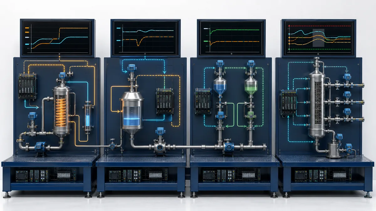
The least complex strategy that reliably handles the mechanism is usually easier to commission and sustain. Feedforward plus feedback can reject a measurable disturbance. Cascade can isolate a fast secondary disturbance. Ratio control can maintain material proportion. Override/selective control can protect an operating limit. An inferential can provide a faster quality estimate. MPC becomes compelling when these pairwise structures become difficult to coordinate or when multiple constraints must be considered together.
| Strategy | Best-fit evidence | Main design requirement | Common misuse | Proof case |
|---|---|---|---|---|
| Cascade | Secondary variable responds earlier than primary | Inner loop substantially faster and dependable | Adding a slow or noisy inner loop | Inner disturbance rejected while outer PV remains controlled |
| Feedforward + feedback | Disturbance is measurable before its effect | Stable disturbance-to-output relationship and feedback trim | Trusting an unmeasured or changing relationship | Matched disturbance with and without feedforward |
| Ratio control | One flow/quantity should follow another | Correct basis, scaling, limits and low-flow behavior | Dividing by a noisy near-zero signal | Ratio maintained through master-flow change and low limit |
| Override/selective | A normal target must yield to a limiting variable | Selector direction, tracking and anti-windup | Treating a selector as a safety function | Smooth takeover and release at the operating limit |
| Decoupling | Known interaction degrades paired loops | Usable interaction model across range | Exact cancellation assumed despite changing dynamics | One setpoint change with reduced cross-effect |
| Inferential | Property is delayed/expensive but correlated measurements exist | Reconciled reference, uncertainty and validation | Using a correlation outside its trained envelope | Independent samples across feed/rate/mode range |
| MPC | Several CVs/MVs interact and constraints matter | Identifiable dynamics, degrees of freedom and valid limits | Applying MPC to broken base loops | Coordinated move reaches target without constraint violation |
| Real-time optimization | Feasible targets should move with economics | Reconciled model, current costs and target governance | Sending an infeasible optimum directly to control | Approved target change remains feasible through lower layers |
Use a decision record rather than an algorithm wish list
For every proposed application, record the operating objective, present manual actions, manipulated degrees of freedom, controlled outcomes, measured disturbances, active limits, process modes, expected dynamic time scale, safety/environmental boundary, source of economic value and falsifiable acceptance test. Then compare candidate structures on performance, implementation effort, operator clarity and lifecycle burden.
Reject a design when it merely moves hidden complexity into custom scripts. A maintainable cascade or selector implemented in the approved BPCS can outperform an impressive but unsupported APC application. Conversely, dozens of interacting selectors and manual operator rules can be a strong signal that a constrained multivariable solution deserves a controlled pilot.
Prove APC readiness before model identification
Gate instruments, valves and base loops
An APC readiness review should use time-series evidence, maintenance history and controlled response tests. Check every candidate measurement for calibration state, engineering units, resolution, sample behavior, filtering, bad-value flags, delay, range and operating coverage. Check each valve or drive for deadband, stiction, saturation, travel limits, position feedback, rate limits and failure behavior. A model fitted to valve stiction may reproduce the test period while failing as soon as maintenance restores the valve.
For base loops, quantify mode availability, oscillation, variance, saturation, interaction and tuning. Confirm manual/auto and remote/local transitions, setpoint tracking, anti-reset windup, output initialization and bumpless transfer. Repair high-impact loops and repeat the observation period before promising APC value.
| Readiness gate | Minimum evidence | Reject or remediate when | Owner |
|---|---|---|---|
| Measurement | Calibration/range/units, quality flags and trend coverage | Bias, clipping, unresolved bad quality or excessive delay | Instrumentation and process engineering |
| Analyzer/lab | Timestamped sample alignment and representative validation | Sample delay/handling or model bias is unknown | Laboratory, analyzer and process owners |
| Final element | Command, position/process response and maintenance condition | Stiction, saturation or fail behavior defeats intended moves | Control and maintenance |
| PID loop | Mode, tuning, oscillation, saturation and disturbance response | Loop spends material time manual or unstable | Control engineer and operations |
| Data history | Time alignment, gaps, compression and mode context | Important transitions are erased or clocks disagree | OT/data owner |
| Process degrees of freedom | Independent MVs and feasible ranges | Claimed MV is already pinned or controlled elsewhere | Process and operations |
| Constraint definition | Source, units, priority, margin and owner | “Limit” is undocumented, contradictory or not measurable | Process, equipment and safety owners |
| Operating modes | Start-up, shutdown, grade/rate and equipment states | One model silently spans incompatible dynamics | Operations and APC engineer |
| Fallback | Receiving logic, tracking, alarm and recovery procedure | Loss of APC creates a bump or undefined target | BPCS, operations and APC owners |
| Benefit baseline | Normalized historical comparison and exclusions | Value is only anecdotal or confounded by other changes | Operations, finance and engineering |
Confirm controllability, observability and safe excitation
MPC needs usable cause-and-effect information. An MV must influence at least one relevant CV within a time scale the application can identify and control. A CV must be measured or estimated with adequate quality. Independent MVs are required to satisfy independent objectives; three requested targets do not create three degrees of freedom when only one actuator is truly available.
Identification moves must be large enough to separate response from noise yet small enough to remain inside the approved operating envelope. Define step sizes, directions, hold times, simultaneous-move rules, abort limits, excluded modes and required staffing before the test. Production pressure is not authority to bypass management of change, operating procedures or independent protection.
Understand how constrained MPC makes a move
Define CVs, MVs and DVs without hiding ownership
A controlled variable (CV) is an outcome the controller should keep at a target, within a zone or away from a constraint. Examples include product composition, column pressure, furnace oxygen, compressor suction pressure or energy intensity. A manipulated variable (MV) is a target the MPC can move, commonly the setpoint of a proven base loop. A disturbance variable (DV) is a measured influence that the model uses for prediction but cannot command, such as feed rate, feed composition, ambient condition or upstream pressure.
Every variable needs more than a tag name. Retain engineering units, source, sample/update expectation, scale, quality definition, valid modes, low/high bounds, move-rate limits, priority, bad-data response, substitution rule and operator display. A temperature in degrees Celsius accidentally modeled as Fahrenheit is not a tuning problem. A flow total mistaken for a flow rate is not a small data-quality issue.
| MPC object | Distillation illustration | Contract question | Degraded response |
|---|---|---|---|
| CV: top composition estimate | Purity target/low limit | Is the inferential reconciled to current lab/analyzer evidence? | Remove from optimization or fall back to conservative target |
| CV: column pressure | Operating zone/high limit | Is measurement fast, independent and linked to protection separately? | Hold/disable affected moves; BPCS remains authoritative |
| CV: reboiler duty | Economic penalty/high equipment limit | Is calculated duty current and physically plausible? | Drop economic objective; retain equipment limit elsewhere |
| MV: reflux-flow setpoint | Adjusts separation and energy use | Is the flow loop remote, healthy and not saturated? | Track current SP; make MV unavailable |
| MV: steam-flow setpoint | Adjusts vapor traffic and separation | Are rate and absolute limits enforced in BPCS too? | Freeze/return to approved base target |
| MV: product draw setpoint | Changes inventory and quality dynamics | Are level/material-balance interactions represented? | Remove MV or switch controller to a reduced configuration |
| DV: feed rate | Predicts load change | Is it measured before its effect and time-aligned? | Continue without feedforward only if tested and approved |
| DV: feed composition | Predicts separation demand | Is analyzer delay/quality explicit? | Mark invalid and increase operating margin or disable model |
Use prediction, objective and constraints as three separate contracts
For an educational linear MPC formulation, predicted future outputs can be summarized as:
Y = F x(k) + G ΔU + H D
where x(k) represents the current estimated state, ΔU the candidate future MV increments and D known/predicted disturbances. The controller selects ΔU to minimize an objective such as:
J = Σ ||Y - R||²_Q + Σ ||ΔU||²_R + ρ ||ε||²
subject to approved absolute MV bounds, MV move-rate bounds, CV limits and any model-specific restrictions. Q weights CV deviation, R discourages excessive movement and ε represents a permitted soft-constraint violation penalized by ρ. This notation explains the structure; it is not a vendor tuning recipe.
Constraint classification matters. A physical or safety-related boundary is not made safe merely by giving it a very large optimization weight. Decide which constraints are hard in the solver, which use explicit slack, which are enforced again in the BPCS, and which belong entirely to independent protection. Make infeasibility visible. Quietly relaxing every limit can produce a numerical solution while breaking the operating contract.
Choose horizons and execution from process dynamics
The prediction horizon must extend far enough to see the material consequences of candidate moves. The control horizon determines how many future moves are optimized independently. The execution interval must capture meaningful dynamics without reacting to measurement noise or consuming needless resources. Faster is not automatically better for a slow distillation composition response; slower is not acceptable when a relevant pressure interaction develops before the next calculation.
Validate the design across the fastest important controlled interaction, the slowest economically relevant response, dead time, analyzer delays and changing process modes. Inspect predicted versus actual response for each important MV–CV pair rather than relying only on an overall fit statistic.
Work through an advanced process control example
Define a hypothetical constrained distillation problem
Consider a fictional distillation unit producing 100 tonnes per hour. Operators must protect a top-product purity minimum, a column-pressure ceiling and a reboiler-duty limit while coordinating reflux, steam and product draw. Feed rate and feed composition change. Separate PID loops already control reflux flow, steam flow, column pressure and inventories, but operators frequently pull the throughput target away from constraints because interactions and delayed quality evidence make the true margin hard to judge.
The proposed MPC has three MVs: reflux-flow setpoint, steam-flow setpoint and throughput/product-draw target. Its CVs are a reconciled top-purity inferential, column pressure, reboiler duty and inventory-related operating zones. Feed rate and available composition information enter as DVs. The MPC can move only remote, healthy base-loop setpoints; BPCS limits and interlocks remain active. If the inferential fails validation, the quality CV becomes unavailable and the controller returns to a documented conservative operating target or disengages according to the mode design.
| Variable | Role | Example normal objective | Example constraint/eligibility | Independent proof |
|---|---|---|---|---|
| Top-product purity inferential | CV | Stay above customer-quality target with measured margin | Valid only inside reconciled model envelope | Time-aligned lab/analyzer samples and residual trend |
| Column pressure | CV | Maintain operating zone | High operating limit plus separate protection | Calibrated pressure and approved test evidence |
| Reboiler duty | CV | Minimize energy for feasible production | Equipment/process high limit | Steam conditions and energy calculation audit |
| Reflux SP | MV | Coordinate separation | Flow-loop remote/healthy; absolute and move limits | SP/PV/output/valve response |
| Steam SP | MV | Coordinate vapor traffic | Remote/healthy; equipment rate and absolute limits | SP/PV/output plus process response |
| Production/draw SP | MV | Raise feasible throughput | Inventory and downstream constraints available | Material balance and receiving-unit capacity |
| Feed rate | DV | Predict load demand | Valid range, quality and time alignment | Independent balance/cross-check |
| Feed composition | DV | Predict separation difficulty | Analyzer/sample delay and quality explicit | Reference sample and timestamp reconciliation |
Calculate a transparent illustrative business case
Suppose a controlled trial supports a sustained throughput change from 100 to 104 tonnes per hour during comparable eligible operation. At 8,000 eligible operating hours per year and an assumed contribution margin of $25/t, the illustrative gross contribution is:
4 t/h × 8,000 h/y × $25/t = $800,000/y
Suppose the higher operating point adds an average 0.2 MW of energy demand and the applicable energy cost is $70/MWh:
0.2 MW × 8,000 h/y × $70/MWh = $112,000/y
If annual software, support, model-maintenance and engineering cost is $180,000/y, the illustrative annual net is:
$800,000 - $112,000 - $180,000 = $508,000/y
For a fictional one-time implementation cost of $600,000, simple payback is:
$600,000 ÷ $508,000/y × 12 = 14.2 months
These numbers are deliberately transparent and hypothetical. They are not a forecast for another process or a claim about any software product. A real study should include product value by grade, yield, giveaway, energy/fuel, utilities, flaring/emissions where legitimately monetized, catalyst/equipment effects, maintenance, off-spec disposition, lost opportunity during testing, licensing, infrastructure, cybersecurity, training and ongoing model support. It should also test downside cases.
| Sensitivity case | Incremental throughput | Margin | Added energy cost | Annual lifecycle cost | Illustrative net/year | Simple payback on $600k |
|---|---|---|---|---|---|---|
| Downside | 2 t/h | $20/t | $160k | $220k | $320k - $160k - $220k = -$60k |
No positive payback |
| Base illustration | 4 t/h | $25/t | $112k | $180k | $508k | 14.2 months |
| Upside sensitivity | 5 t/h | $30/t | $140k | $180k | $1.20m - $140k - $180k = $880k |
8.2 months |
Prove benefit with matched periods and availability
The controller cannot claim all improvement after its start date. Normalize for feed, rate, product grade, ambient conditions, equipment lineup, catalyst age, upstream/downstream constraints, planned maintenance and price assumptions. Define an eligible-period mask before comparing APC on/off results. Retain controller service factor, CV/MV availability, time at constraints, operator interventions and constraint violations alongside the economic measure.
A persuasive report separates gross opportunity, achieved technical effect, controller availability and monetization. For example, reduced variance may be technically real but have no economic value unless it permits a target shift, prevents giveaway, increases feasible rate or reduces consumption. Conversely, a throughput gain during a favorable feed campaign should not be booked entirely to APC.
Live mini-lab
Try it: press START, then STOP
A stop-dominant seal-in rung: START latches the motor output through its own contact, and STOP breaks the circuit.
Watch the output lamp: it stays on after START until you press STOP.
Free to start · runs in your browserOpens plcsimulationsoftware.com — same team
Build and validate the dynamic model
Plan step tests as controlled plant experiments
Create a test matrix for each candidate MV. State its current range, proposed positive/negative move, expected affected CVs, approximate delay/settling time, constraints, excluded simultaneous changes, abort criteria and responsible console/field personnel. Log process mode, disturbances, operator actions, maintenance events and data-quality changes. Use sufficiently long holds to observe the relevant response; repeated short movements may excite only noise or fast base-loop behavior.
Do not force unsafe or economically reckless moves merely to improve identifiability. Historical data, designed tests, first-principles knowledge and hybrid approaches can be combined, but uncertainty must remain visible. If safe operation never excites an interaction, the model should not pretend that behavior is known far outside the observed envelope.

Validate models outside the fitting interval
Reserve representative periods that were not used to fit parameters. Compare predicted and measured direction, delay, initial slope, gain, settling shape and cross-variable response. Inspect residual bias and correlation with mode, rate or disturbances. A high aggregate fit can hide the wrong sign on an important interaction or a delay error that causes poor closed-loop moves.
Document the valid operating region and configuration: process mode, equipment lineup, base-loop tuning, valve condition, analyzer state, sample interval and model version. Use multiple models or explicit scheduling where modes genuinely differ. Do not silently average start-up, steady production and grade-transition dynamics into one controller.
Engineer mode, authority and operator handoff
Use explicit states instead of one ambiguous on/off bit
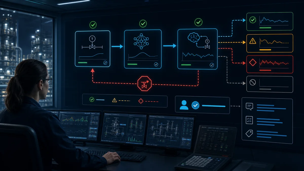
An APC application should expose why it can or cannot act. A practical state model may include OFF, READY, ADVISORY, CLOSED_LOOP, DEGRADED and RETURN_TO_BASE. The exact implementation varies, but transitions, permissions and outputs must be deterministic. “Solver running” is not equivalent to “every MV is available” or “economic optimization is active.”
READY can mean infrastructure, models, signals and base loops pass current eligibility checks. ADVISORY calculates predicted moves without writing them. CLOSED_LOOP permits bounded writes for eligible MVs. DEGRADED retains an approved reduced configuration after a noncritical variable is lost. RETURN_TO_BASE tracks the receiving setpoints/outputs and transfers authority through a documented rate-limited or bumpless sequence.
| State | APC calculation | Writes allowed | Operator evidence | Exit condition |
|---|---|---|---|---|
| OFF | Stopped or non-authoritative | None | Reason, last state and base targets visible | Approved start plus all readiness gates |
| READY | Current status/model checks may run | None | Eligible/ineligible CVs, MVs and DVs | Operator/automation request to advisory or closed loop |
| ADVISORY | Predictions and recommendations run | None | Proposed moves, predicted outcomes and constraint reason | Acceptance to closed loop or loss of readiness |
| CLOSED_LOOP | Repeated constrained optimization | Bounded eligible MV targets | Active objectives, constraints, moves, service factor | Operator request, eligibility loss, fault or procedure |
| DEGRADED | Approved reduced model/configuration | Only documented subset | Missing variable, reduced capability and consequence | Restoration/revalidation or return to base |
| RETURN_TO_BASE | Tracking and handoff logic | Only controlled transition actions | Target destination, rate and completion | Base loop owns stable target; then OFF/READY |
Design bumpless transitions and independent receiving limits
Before engagement, the APC's internal targets should track the actual receiving BPCS setpoints. On engagement, the first commanded value should equal or closely match the current value, followed by approved move limits. On disengagement, the BPCS retains the last acceptable setpoint or returns to a predefined operator/base target according to process risk. Integral action, selectors and remote/local modes need matching anti-windup and tracking behavior.
Enforce critical setpoint ranges and rates in the receiving control system as well as the optimizer. Network delays, stale calculations, configuration error or a compromised server should not allow an unbounded write. The BPCS should reject invalid quality, wrong mode, stale timestamp, implausible change or unauthorized source and should record the reason.
Give operators causes, consequences and permitted actions
The main display should answer: What is APC trying to achieve? Which CV is limiting? Which MV has freedom? Which variable was rejected and why? What move is being applied? What does the model predict? What happens if APC is taken out? Avoid flooding the console with every internal matrix value. Provide drill-down trends and model diagnostics for the support team.
Train with scenarios, not slides alone: an analyzer becomes bad, a valve saturates, one PID changes to local/manual, a process mode changes, a CV constraint conflicts with the economic objective, the APC server restarts, communication is lost and an operator deliberately returns to base control. Each scenario needs expected indications, authority, communication and recovery criteria.
Commission the application in controlled stages
Progress from offline evidence to bounded closed loop
A robust lifecycle separates installation success from control success. Build interfaces and models in an offline/test environment where possible. Replay historical and designed-test data. Run current calculations without writes in shadow/advisory mode. Compare predicted responses and proposed moves with process-engineer and operator expectations. Then close a limited subset of variables during a staffed approved window before expanding authority.
- Freeze the opportunity statement, owner, baseline, risk boundaries and acceptance criteria.
- Repair instrumentation, valves and base loops; repeat readiness measurement.
- Approve and execute identification tests with abort criteria and complete event logging.
- Fit models, reserve validation data and record valid modes/ranges.
- Configure CV/MV/DV definitions, limits, priorities, fallback and receiving-system enforcement.
- Perform offline replay, interface/failure tests and cybersecurity/change review.
- Run shadow/advisory mode through representative disturbances and operator shifts.
- Close a limited application with conservative move limits and active support.
- Challenge constraints, data loss, MV saturation, mode changes and return-to-base cases safely.
- Expand only after technical, operator and process acceptance; freeze the approved baseline.
- Measure normalized benefits and controller service factor over a representative period.
- Transfer maintenance ownership, diagnostics, backups, model-monitoring limits and revalidation triggers.
Define a test matrix that can fail meaningfully
| Acceptance case | Controlled stimulus | Required evidence | Example pass definition to tailor |
|---|---|---|---|
| Initial engagement | APC tracks current base targets, then closes | MV target/output and CV trends | No material bump; every first move within approved limit |
| Measured disturbance | Safe representative feed/load change | DV timing, predictions, MVs, CVs | Response direction correct and constraints maintained |
| CV approaches limit | Approved target/disturbance near operating bound | Active-constraint reason and competing targets | Controller backs away with defined priority |
| MV saturates | Use safe approved limit or simulated interface case | MV availability, anti-windup/tracking, redistribution | No repeated impossible request; other MVs act only as modeled |
| Bad CV/DV quality | Simulate quality flag in test path | Eligibility, operator message and fallback | Variable removed/substituted only by approved rule |
| Base loop leaves remote | Change approved test loop mode | Write rejection, APC state and BPCS behavior | MV becomes unavailable; handoff has no bump |
| Communication/server loss | Controlled test environment or window | Stale-write rejection and base-control state | BPCS retains approved control; event is visible and recoverable |
| Restart/recovery | Restart approved component | version/model/config checks and tracking | No automatic unreviewed closed-loop resumption |
| Return to base | Operator requests disengagement | tracking, target rate and final authority | Stable base ownership with documented final targets |
| Benefit trial | Predetermined matched on/off or staged comparison | eligible periods, confounders and normalized KPIs | Effect and uncertainty meet pre-agreed decision rule |
Preserve configuration and rollback evidence
Archive the deployed models, variable contracts, unit/scaling maps, execution interval, constraint values, priority/weight configuration, interface configuration, server/application version, BPCS receiving logic, operator displays, test results, known limitations and approval record. Backups are not credible until a controlled restoration or independent comparison demonstrates they can recreate the intended state.
Rollback is more than uninstalling software. It defines who returns targets, how retained values are handled, which server writes are disabled, how the BPCS configuration is restored, how operators confirm authority and how post-change process behavior is observed.
Protect data and model health after go-live
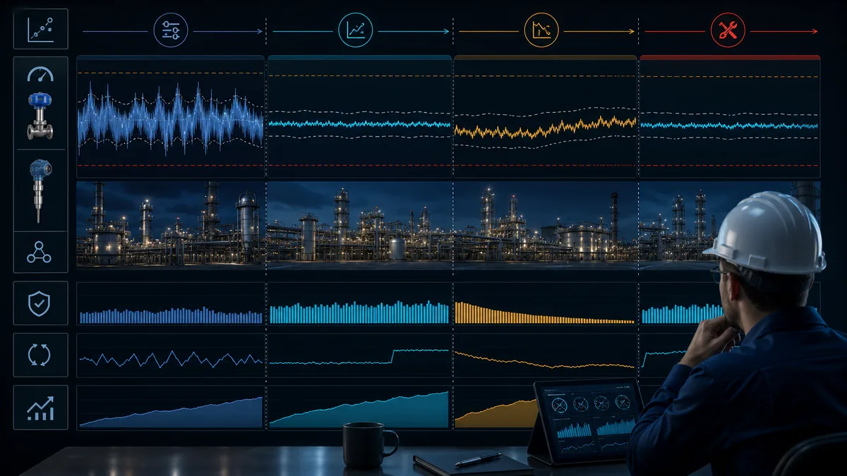
Monitor input credibility before controller performance
APC degradation often begins outside the solver. Track missing/bad/flatlined/clipped measurements, timestamp skew, analyzer validation residuals, valve travel and stiction indicators, base-loop mode and saturation, MV availability, model prediction error and operation outside the identified range. A controller that is available but running on biased data is not healthy.
Use a hierarchy: input and base-control health; model residuals; controller eligibility/service factor; move behavior; CV variance/constraint performance; normalized process/economic outcomes. This order prevents teams from retuning weights to compensate for a biased transmitter or damaged valve.

Define revalidation triggers before performance decays
Trigger review after feedstock or grade changes, major maintenance, equipment modifications, sensor/analyzer replacement, valve work, BPCS tuning changes, tag/scaling changes, APC or operating-system upgrades, control-network changes, sustained residual drift, repeated operator disengagement or a shift in the active constraint pattern. Some events need only confirmation; others require new identification and model work.
| Health signal | Possible interpretation | First evidence | Wrong first response |
|---|---|---|---|
| One CV residual develops steady bias | Sensor/inferential bias or unmodeled operating shift | Independent reference and mode/feed correlation | Increase CV weight |
| Oscillation appears in several predictions | Base-loop oscillation, interaction or execution mismatch | PID/MV trends and timing | Shorten horizon blindly |
| MV requested at limit continuously | True active constraint, lost degree of freedom or wrong target | Physical/BPCS limit, valve state and objective | Increase MV high limit without approval |
| Controller service factor falls | Eligibility, operator trust, bad data or mode coverage issue | Reason-code Pareto and shift/event timeline | Report only total uptime |
| Benefit erodes while control metrics look stable | Economics/baseline changed or target shift no longer valuable | Normalized outcome and current value assumptions | Claim original benefit indefinitely |
| Operators repeatedly switch off after certain moves | Display, model, tuning or operational conflict | Interview plus move/prediction/process trace | Remove operator authority or retrain only |
| Prediction error increases after turnaround | Equipment/configuration dynamics changed | Pre/post asset, tuning and response comparison | Reuse old model without validation |
| APC status is green but quality is off-spec | Wrong CV/reference, delayed analyzer or eligibility gap | Raw quality evidence and timestamps | Treat green status as end-to-end proof |
Select advanced process control software by lifecycle capability
Evaluate the complete engineering and operating workflow
Advanced process control software should be evaluated against the actual application: regulatory/sequence integration, historian and analyzer interfaces, data reconciliation, identification, model structure, constraint handling, inferentials, offline simulation, shadow mode, online deployment, operator displays, reason codes, version control, access control, backup/restore, monitoring, model maintenance, high availability, support and licensing. A polished optimizer is not sufficient if the site cannot diagnose why one MV is unavailable at 02:00.
Run a proof of fit with representative tags, dynamics, failure states and user roles. Require the vendor/integrator to demonstrate quality loss, timestamp problems, saturation, mode change, solver failure, server restart, version rollback and reduced-configuration behavior—not only a nominal closed-loop response.
| Capability | Proof-of-fit question | Acceptance evidence | Lifecycle risk if weak |
|---|---|---|---|
| Data connectivity and quality | Can it preserve source timestamps, quality, units and mode context? | Representative good/bad/stale/out-of-order cases | Plausible calculations from invalid data |
| Identification/modeling | Can engineers inspect responses and validation residuals? | Held-out dataset and versioned model report | Black-box model cannot be defended or maintained |
| Constraints/infeasibility | Are hard, soft and prioritized limits explicit? | Deliberately conflicting test objectives | Hidden relaxation or unexplained controller drop |
| Reduced configurations | Can control continue safely after selected variables fail? | CV/MV loss matrix and observed transitions | One failure disables everything or silently changes authority |
| Operator experience | Are objective, active constraint, moves and off reasons visible? | Console walkthrough with abnormal scenarios | Low trust and avoidable service-factor loss |
| BPCS integration | Are writes bounded, tracked, quality-gated and audited? | Interface and loss/restart tests | Bumps, stale writes or undefined target ownership |
| Version/rollback | Can exact models/configuration be compared and restored? | Controlled restore to test environment | Unrecoverable drift and slow incident response |
| Monitoring | Can reason codes, residuals, saturation and value KPIs be trended? | Health dashboard and alert workflow | Slow degradation remains unnoticed |
| Cybersecurity | Are identities, roles, services, logs and updates manageable? | Architecture/threat/change review | Excessive privilege and unmanaged attack surface |
| Commercial/support fit | What licensing, infrastructure, skills and response are required? | Total-cost/support scenario over lifecycle | Business case omits recurring burden |
Treat current vendors as candidates, not a universal ranking
As of the review date, official pages from Honeywell, AspenTech, AVEVA and KBC describe APC/MPC and process-optimization offerings. ABB and Emerson publish process-control and predictive-control capabilities within their ecosystems, while MathWorks documents MPC design, simulation and deployment tooling. Product scope, names, platform requirements and licensing can change. Their presence here establishes a market category, not an endorsement or a claim that the products are equivalent.
Shortlist from site architecture and support reality. An installed DCS ecosystem may make native integration attractive; a cross-platform estate may prioritize open, documented interfaces; a research or embedded application may need different modeling/deployment tools. Score every candidate against one common requirements matrix and a matched pilot. Keep vendor benefit statements attributed to the vendor until the site independently validates them.
Troubleshoot APC from the first failed evidence boundary
Capture the state before switching or retuning
When performance deteriorates, preserve the timeline: process mode, controller state, eligible CV/MV/DV set, active constraints, objective terms, predictions, applied moves, raw measurements and quality, base-loop modes/outputs, valve positions, analyzer/lab results, alarms, operator actions, model/configuration versions and recent changes. A reset can remove the evidence that separates a bad input from solver, interface or process problems.
Start at the process and data foundation, then move through model and optimizer to the receiving BPCS and physical response. If the optimizer requests the correct bounded setpoint but the PID loop is saturated, the APC solver is not the first failed boundary. If the BPCS receives no new target, investigate eligibility, calculation, communication and write permissions before blaming a valve.
| Symptom | Plausible causes | Highest-value next check | Avoid |
|---|---|---|---|
| APC will not enter closed loop | Readiness bit, bad data, base-loop mode, permission or model configuration | Explicit ineligible reason for every CV/MV and interface health | Toggling enable repeatedly |
| APC enters then drops out | Constraint conflict, quality transition, stale data, write rejection or solver event | Time-aligned state/reason and calculation log | Increasing every tolerance |
| Moves are directionally wrong | Model sign/index/unit error, wrong tag, mode change or unmeasured disturbance | Step-response record against live source-to-destination trace | Retuning weights before verifying mapping |
| Moves are too aggressive | Gain/delay mismatch, move penalty/limit, execution interval or base-loop change | Predicted versus measured response and actual rate limits | Depending on operator intervention as the normal limiter |
| Moves are too timid | Active constraint, unavailable MV, excessive penalty, model uncertainty or no economic drive | Objective/constraint contribution and degrees of freedom | Raising limits without process approval |
| CV prediction drifts | Sensor/inferential bias, model aging, unmodeled disturbance or mode mismatch | Independent measurement and residual by operating condition | Refitting before fixing biased data |
| One MV chatters | noisy CV/DV, execution/tuning, valve stiction or competing controller | raw/filtered signals, PID output and valve position | Adding filter until the symptom disappears |
| APC says active but no value appears | Objective not shifted, limiting constraint elsewhere, low availability or poor baseline | matched eligible-period effect and constraint/activity distribution | Repeating the original business-case promise |
| Operators disable APC | unexplained moves, false alarms, bad handoff, wrong objective or workflow burden | shift interviews plus preceding move/state trends | Treating all disengagement as resistance to change |
| Restart changes targets | missing tracking, retained state, version mismatch or auto-resume logic | startup sequence, deployed checksum and receiving setpoints | Allowing automatic writes before readiness review |
Diagnose constraint and model problems separately
A controller legitimately held at a constraint may show a persistent target error. That is not necessarily bad tuning: the feasible solution cannot satisfy every target. Show the active constraint, priority and sacrificed objective to operators. If the claimed constraint is not physically active, trace units, scaling, tag mapping, limit source and configuration version.
A model problem appears as persistent or structured prediction error after input data and mode are proven. Inspect individual response pairs, not only an aggregate score. Re-identification may be warranted after equipment or operating changes, but a new model must pass the same held-out validation, shadow and fallback tests as the original.
Keep safety, process-risk and cybersecurity boundaries explicit
Treat APC changes through the site's process-safety lifecycle
In US-covered processes, OSHA's Process Safety Management rule includes management-of-change requirements for changes to process chemicals, technology, equipment, procedures and facilities, subject to the rule's scope and exceptions. APC projects can change targets, operating envelopes, modes, procedures, alarms and how people interact with the process. Determine applicability with the site's competent process-safety/legal authority; do not assume “software only” means no MOC.
Document technical basis, safety/health effects, required procedure changes, duration, authorization and training. Review hazard analyses and alarm/interlock implications. Verify that BPCS and SIS functions, trip settings, relief design assumptions, equipment limits and environmental constraints remain valid for the new operating region. APC may keep operation closer to a normal constraint; it must not consume undocumented safety margin.
Preserve independent protection and safe work practices
An optimization constraint is not an SIS function, relief device or mechanical design limit. The solver, network, server and ordinary measurements can fail. Independent protection must remain engineered and tested for its required role. Any field test, valve movement, instrument work or control change must follow approved isolation, hazardous-energy, electrical, process and environmental procedures.
The simulator practice link on this page is deliberately bounded to a deterministic educational PID process. It cannot validate a commercial MPC model, real process constraints, plant dynamics, SIS independence, relief capacity or safe operating limit.
Secure the APC data and write path as OT
NIST SP 800-82 Rev. 3 frames OT cybersecurity around operational performance, reliability and safety. Inventory APC servers, engineering stations, historians, interfaces, model repositories, operator clients and receiving control endpoints. Segment allowed flows, use named least-privilege identities, restrict configuration and writes, protect time sources, log changes and write attempts, manage remote access, test backup/restoration and evaluate updates in a representative environment.
| Security boundary | Control objective | Validation case |
|---|---|---|
| APC-to-BPCS write path | Only authenticated/authorized source, tags, modes, ranges and rates | Unauthorized, stale, bad-quality and out-of-range writes are rejected/logged |
| Engineering/model repository | Approved people can change versioned models/configuration | Compare deployed checksum, approval and rollback copy |
| Data sources/time | Measurements retain identity, quality and credible timestamps | Bad/stale/skewed data invokes designed eligibility response |
| Remote/vendor support | Explicit approved route, duration, identity and monitoring | Access enable/use/disable evidence and session review |
| Server/client hardening | Necessary services and roles only, managed changes | Baseline comparison and recovery test after update |
| Backup and recovery | Recreate known approved application without unsafe auto-resume | Restore in test path, verify configuration, track targets before writes |
| Monitoring | Detect service, data, model and authorization anomalies | Alert-to-triage exercise linked to APC operating evidence |
Sustain benefits as an operating system
Assign named ownership and a review cadence
Sustainment needs an operations sponsor, process engineer, control/APC engineer, instrumentation/maintenance owner, OT/platform owner and economic KPI owner. Define daily or shift review for off reasons and constraints, weekly review for availability/data/base-loop health, monthly review for model residuals and normalized technical value, and periodic governance for models, cybersecurity, licenses, training and business assumptions. Scale cadence to process criticality and change rate.
Do not reward the team for APC uptime alone. A controller can remain on while delivering no value or operating on weak data. Balance service factor with eligible-variable availability, constraint performance, base-loop/valve health, prediction error, operator interventions, quality/yield/rate/energy outcomes and incidents or limit excursions.
Use an evidence scorecard rather than one promised savings number
| Scorecard layer | Example measures | Decision it supports |
|---|---|---|
| Foundation | measurement availability, analyzer reconciliation, valve stiction, PID auto/remote time | Is the control foundation still credible? |
| Controller health | APC service factor, eligible CV/MV count, off-reason Pareto, solver/interface events | Can the application exercise its intended authority? |
| Model health | CV residual bias/variance, pairwise response exceptions, operation outside envelope | Does the model still represent current operation? |
| Control effect | CV variance, target shift, constraint time/violations, MV movement/saturation | Is APC changing technical behavior as designed? |
| Operator use | intentional disengagement, unplanned overrides, transition success, support calls | Is the workflow understood and trusted? |
| Process value | normalized throughput, yield/giveaway, energy, quality, emissions or equipment metric | Does technical effect create attributable value? |
| Risk/lifecycle | MOC completion, incidents, patches, backup tests, model/version review | Is value being delivered within the approved lifecycle? |
Practise the foundation without overstating the simulator
Use PID process practice to strengthen the base layer
The PID process simulator provides a deterministic first-order process in which learners can change gains, observe overshoot, settling, final error and integrated absolute error, and compare disturbance cases. That is useful preparation for APC because higher layers depend on stable, understandable regulatory behavior.
The browser lab is not commercial advanced process control software. It does not identify or commission a multivariable MPC, represent a real distillation column, validate plant constraints, connect to a DCS, or replace process/safety engineering. Use it to rehearse measurement, feedback, saturation and disturbance reasoning; then validate models, limits, handoff and fallback in the approved APC/DCS environment with qualified site personnel.
Follow a staged APC training path
- Prove instrumentation scaling, quality and failure states.
- Tune and diagnose first-order PID behavior, including saturation and disturbance response.
- Build cascade, ratio, feedforward and override examples in an approved lab environment.
- Learn dynamic response, dead time, interaction and degrees of freedom from controlled data.
- Formulate CV/MV/DV contracts and hard/soft constraint decisions.
- Simulate a multivariable controller offline and validate against held-out scenarios.
- Practise advisory/closed-loop/degraded/return-to-base transitions.
- Review a real application under site MOC, cybersecurity, operator and safety governance.
Diagnostic answer map for advanced process control queries
APC versus PID in one decision
Use PID and advanced regulatory structures when a small number of loops can reject disturbances and respect limits transparently. Use MPC when several controlled and manipulated variables interact, future response matters and explicit constraints must be coordinated. In either case, repair measurements, final elements and base loops first; MPC normally supervises those loops rather than replacing them.
The evidence needed before an APC project
Start with time-aligned measurement quality, valve/drive response, base-loop modes and performance, independent degrees of freedom, documented constraint ownership, representative operating modes, safe test authority, a bounded BPCS write contract, predictable fallback and a normalized economic baseline. A model-development milestone should not override a failed readiness gate.
The meaning of a constrained MPC move
The controller predicts how eligible CVs will respond to candidate MV moves and measured DVs, then chooses a bounded move sequence that balances target deviation, movement and permitted soft-constraint slack. Only the first move is applied before the calculation repeats. Hard solver constraints, receiving-system limits and independent protection remain separate contracts.
The first evidence to inspect when APC performs badly
Capture the operating mode, CV/MV/DV eligibility, active constraints, prediction, requested and applied moves, raw signal quality, base-loop state, final-element response and recent configuration changes before reset. Find the first mismatch from physical process and data through model, solver, interface, BPCS and process response before retuning weights.
The software-selection answer
Select against the whole lifecycle: data quality, identification, held-out validation, constraint behavior, reduced configurations, shadow testing, operator reason codes, bounded control-system integration, version/rollback, health monitoring, cybersecurity, support and total cost. Demonstrate abnormal states using representative data; do not infer operational fit from a nominal optimizer demo.
Frequently asked questions
What is advanced process control and how is it different from PID control?
Advanced process control is an umbrella for strategies beyond ordinary independent feedback loops, including cascade, feedforward, ratio, override, inferentials and multivariable MPC. PID commonly regulates one primary variable; MPC predicts several interacting variables and selects constrained moves. APC normally supervises proven PID loops rather than replacing them.
Which control strategies count as advanced process control?
Usage varies by organization. Advanced regulatory control commonly includes cascade, feedforward, ratio, selective/override and decoupling strategies. Broader APC programs add inferential measurements, MPC and an interface to real-time optimization. Always state the actual method instead of assuming the label APC defines one algorithm.
When should a plant use cascade, feedforward, ratio control, MPC or real-time optimization?
Use cascade for a faster measurable secondary disturbance, feedforward for an early measured disturbance, ratio for proportional quantities and override for a limiting variable. Consider MPC when several CVs and MVs interact and explicit constraints matter. Consider real-time optimization when economically preferred feasible targets should change with costs and process conditions.
What prerequisites are needed before an APC project?
Prove calibrated and time-aligned measurements, responsive final elements, stable base PID loops, usable degrees of freedom, documented operating constraints, representative data, separable process modes, safe identification authority, BPCS write limits, operator ownership, fallback and a normalized benefit baseline. Repair failed gates before model building.
How do I calculate the business case for advanced process control?
Define an attributable technical change, eligible operating hours and value per unit; deduct incremental energy, quality, maintenance, licensing, infrastructure and support. Include implementation cost and downside sensitivity. After deployment, use matched or normalized periods and controller availability rather than assigning every post-start improvement to APC.
What is a practical advanced process control example?
A distillation MPC can coordinate reflux, steam and production targets to keep purity, pressure, energy and inventories inside constraints while responding to feed changes. The example on this page shows the CV/MV/DV contract and a disclosed hypothetical business calculation. A real design requires plant-specific models, limits and safety review.
How is model predictive control commissioned and constrained safely?
Commission through readiness repair, approved identification, held-out model validation, offline replay, shadow/advisory operation, conservative limited closure and safe failure/recovery tests. Separate hard and soft optimization constraints, enforce critical ranges/rates again in the BPCS, and retain independent protective systems and approved management of change.
What data quality problems cause advanced process control to fail?
Bias, wrong units/scaling, stale or misaligned timestamps, excessive compression, clipped or flatlined signals, analyzer/sample delay, unmarked bad quality, valve stiction, base loops in manual and mixed operating modes can all invalidate predictions. Monitor those foundations before retuning the optimizer.
How do operators take an APC application in and out of service?
Use explicit eligibility and states such as ready, advisory, closed loop, degraded and return to base. Track actual BPCS targets before engagement, apply bounded first moves, show active constraints/off reasons, and execute a documented bumpless handoff that leaves base control with known stable targets.
Which advanced process control software capabilities matter during selection?
Evaluate connectivity and data quality, identification and held-out validation, hard/soft constraints, reduced configurations, offline/shadow testing, operator reason codes, bounded BPCS integration, versioning/rollback, monitoring, cybersecurity, support and lifecycle cost. Run matched abnormal-condition tests with representative data instead of selecting from a feature list alone.
Sources, review scope, and limitations
Primary and authoritative sources used for this guide
- ISA, “Advanced process control: Indispensable process optimization tool”: practitioner overview of APC, regulatory foundations, MPC and sustaining performance.
- ISA Automation Body of Knowledge, third-edition overview: professional automation-domain scope; the linked commercial book is not reproduced here.
- Qin and Badgwell, “A survey of industrial model predictive control technology”: peer-reviewed industrial MPC architecture, technology and application survey.
- International Federation of Automatic Control, MPC overview collection: publication context for peer-reviewed control research; individual application claims require their linked papers.
- Journal of Process Control: peer-reviewed process-control research venue, including current MPC applications; no single paper is treated as a universal plant result.
- MathWorks Model Predictive Control overview: official product documentation for MPC design, simulation, constraints and deployment concepts; product-specific, not a neutral standard.
- MathWorks MPC constraints documentation: product-specific explanation of manipulated/output constraints and softening behavior.
- Honeywell Advanced Process Control: current vendor description of its APC portfolio and claimed capabilities; claims remain vendor-attributed.
- AspenTech Advanced Process Control: current vendor application page for APC/MPC workflow and benefits; claims require site validation.
- AspenTech DMC3 product page: current vendor product scope for adaptive MPC and related workflow; licensing/version details must be confirmed directly.
- AVEVA APC: current vendor description of its advanced-process-control product; benefits and compatibility remain product/site specific.
- KBC PACE Advanced Process Control: current vendor description of PACE APC; it is a candidate source, not an independent ranking.
- ABB process control systems: current vendor ecosystem entry point for process-control and optimization capabilities; exact APC functions depend on selected products/versions.
- Emerson DeltaV Predict and Control: current vendor ecosystem description of predictive and advanced-control capabilities; verify exact module/version support.
- NIST SP 800-82 Rev. 3: current final US guidance for operational-technology cybersecurity with safety, reliability and performance considerations.
- CISA Industrial Control Systems resources: current US OT/ICS advisories and defensive resource entry point.
- OSHA 29 CFR 1910.119, Process Safety Management: US PSM scope, operating procedures, training, pre-startup safety review and management-of-change requirements where applicable.
- OSHA 29 CFR 1910.147, Control of hazardous energy: US hazardous-energy-control boundary for servicing/maintenance in its scope.
- OSHA 29 CFR 1910.333, electrical work practices: US de-energization and electrical safe-work-practice boundary in its scope.
- IEC 61511-1:2016: functional-safety lifecycle requirements for the process industry; the standard is referenced, not reproduced, and applicability requires competent assessment.
- ISA/IEC 61511 process safety standards page: ISA committee and standards context for process-sector safety instrumented systems.
- ISA-18 alarm management committee page: alarm-management lifecycle context relevant when APC changes alarm behavior or operator response.
- ISA-101 HMI committee page: HMI lifecycle and human-machine-interface context relevant to APC operator displays.
Review and safety limitations
This guide is a vendor-neutral educational framework. It is not an APC/MPC design specification, process model, constraint authority, tuning file, software recommendation, independent benefit study, cybersecurity architecture, HAZOP/LOPA, relief or equipment-limit assessment, SIS design, MOC approval, operating procedure or field-test authorization. The equations and distillation/business examples are intentionally simplified; the $508,000/y net and 14.2-month payback are fictional arithmetic, not observed product or customer results.
The nine original generated visuals are explanatory abstractions. They do not establish piping, instrument, network, solver, model, constraint, alarm, trip or operator-interface design. Product names and official vendor capability pages were reviewed on the date above; verify current names, releases, dependencies, security support, licensing and compatibility with each vendor.
Use qualified process, control, instrumentation, operations, maintenance, safety, cybersecurity and financial personnel; current plant documentation and process-safety information; approved safe operating limits and independent protection; representative data and controlled tests; and site change, access, isolation and recovery procedures. Revalidate after changes to feed/grade/rate, equipment, instruments/analyzers, valves/drives, PID tuning/modes, tags/scaling/time, model/constraints/objectives, APC/DCS/interface software, network/identity, operating procedures, safety/environmental assumptions or economic basis.
Now run it · free to start
Tune a PID loop against a live process model
Change the setpoint and loop terms, then measure overshoot, settling time and error in a browser PID lab. Free to start, nothing to install.
Ownership disclosure: PLC Programming IO and PLC Simulation Software are operated by the same publisher.
PLC Programming IO Editorial Team
Industrial automation education, references, and software testing
The PLC Programming IO Editorial Team publishes sourced industrial-automation education and documents how material is reviewed, tested, and corrected. A team byline means the publisher is responsible for the page; it does not represent a fictional person or imply an engineering licence.
Coverage:
- • PLC programming concepts and examples
- • Vendor software tutorials and comparisons
- • SCADA, HMI, protocols, and instrumentation
- • Training, careers, and reference material
Review standard:
- • Prefer primary and official sources
- • Record software versions when material
- • Separate tested facts from estimates
- • Publish material corrections
Important scope note
This site provides education, not project-specific engineering approval. Safety, code, and compliance decisions require a qualified person with access to the actual machine and jurisdiction.