Delta PLC PID Program Example: DVP Oven Control
Build and commission a Delta DVP PID temperature loop with explicit target selection, engineering-unit scaling, protected parameter memory, fixed sampling, manual/auto tracking, output limits, autotune safeguards and acceptance evidence.
Review status: Editorially reviewed against current Delta PLC product, download-center, DVP starter-kit, DVP-ES3 hardware, software-selection and simulation guidance plus a dated Delta Industrial Automation regional PID oven example; exact CPU, firmware, software, instruction signature, parameter offsets, numerical formats, units, module configuration and autotune modes require verification in the target-specific Delta manual and on an authorized test system
Direct answer
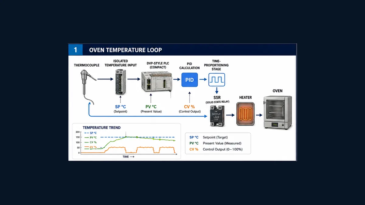
For a reliable Delta PLC PID program example, identify the exact DVP CPU, firmware and ISPSoft or WPLSoft version before assigning a single device. Decide whether the PID calculation belongs in the PLC CPU, inside a DVP temperature module such as an applicable DVP-04TC configuration, or inside a connected AC drive or temperature controller. Those are three different control paths. Then scale the process value (PV) and setpoint (SP) into declared units, reserve the complete PID parameter block, execute the supported PID instruction at a fixed interval, separate requested from applied control output (CV), and test manual/automatic transfer, invalid PV, saturation, restart and actuator failure before tuning.
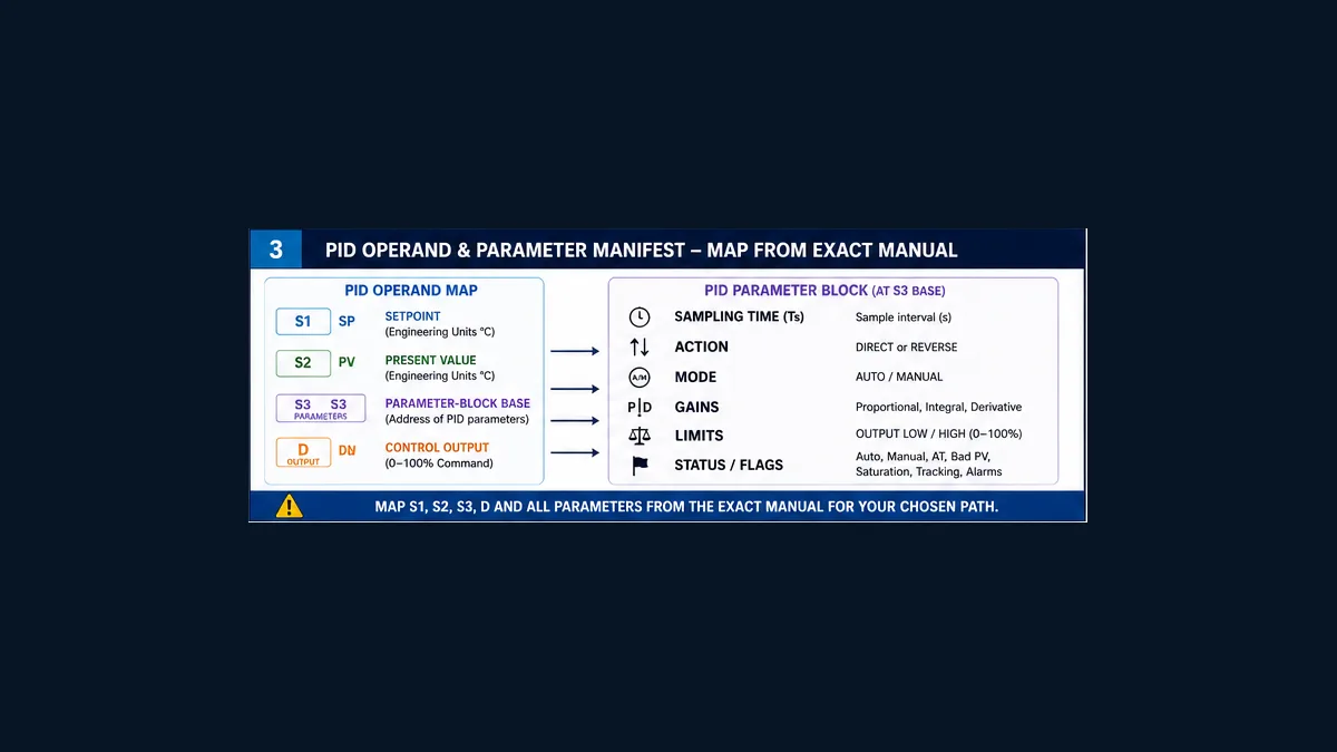
For the CPU-instruction route, Delta DVP documentation commonly presents the conceptual operand shape as PID S1 S2 S3 D: S1 is the setpoint source, S2 is the measured process value, S3 identifies a parameter-block base, and D receives the control output. That is a map for reading the correct manual—not universal copy-and-paste code. The permissible devices, parameter-block length and offsets, numeric representation, execution rule and mode values depend on the exact CPU/manual revision.
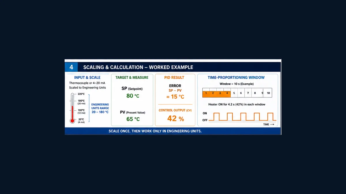
The worked example below controls a training oven. It uses a 20–180 °C PV range, an 80 °C operating setpoint and a 0–100% heater demand so the engineering logic is visible. It does not supply universal D register numbers or PID gains. Those would create false compatibility. Download the Delta DVP PID loop design register and 17-test acceptance matrix to turn the example into a reviewed, target-specific design.
First choose which Delta product actually owns PID
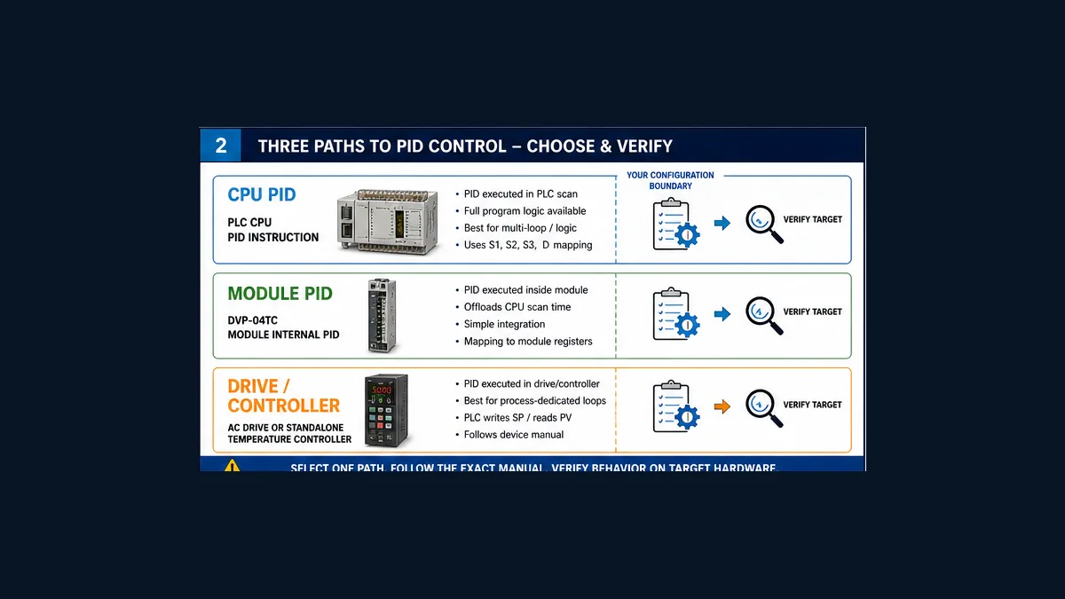
Search results for “Delta PLC PID” mix PLC instructions, temperature-module functions, AC-drive PID, DTC temperature controllers, training videos and legacy examples. Similar screen labels do not make those implementations interchangeable.
| Control path | Where the algorithm runs | What the PLC may do | Manual that governs the result | Main integration risk |
|---|---|---|---|---|
| DVP CPU PID instruction | PLC scan/execution context | scale SP/PV, call PID, constrain and apply CV | exact CPU programming manual | wrong instruction revision, parameter offset, units or timing |
| temperature-module internal PID | intelligent temperature module | configure module, exchange values/status, authorize mode | exact module instruction/operation manual | treating module buffer/control registers as CPU PID operands |
| drive/controller internal PID | VFD, servo drive or standalone controller | send SP, enable/mode and read status | exact drive/controller manual | creating a second loop that fights the device’s internal loop |
Use one authoritative calculation path unless a documented cascade architecture intentionally uses two loops. If a VFD already closes a pressure loop, adding an unrelated CPU PID that also changes the speed reference can cause competing integral action. If a temperature module offers internal PID, its configuration and sample behavior belong to that module’s manual; a CPU PID parameter table cannot simply be written into it.
The Delta temperature-module guide covers module identification, signal type, channel data and diagnostics. The controller-independent PID program guide covers the underlying architecture. This page owns the Delta DVP CPU implementation decision and oven commissioning workflow.
Record the exact Delta target before programming
“Delta DVP” is a family, not a complete compatibility statement. Record the CPU catalog, firmware, expansion modules, electrical design, project format and engineering-software release. Delta’s own support material distinguishes ISPSoft and WPLSoft; a project created for one environment should not be assumed to behave identically in another. The current download center is the right starting point for target documentation, but a search snippet or third-party PDF title is not sufficient evidence.
Build this compatibility manifest:
| Surface | Record before implementation | Why it matters |
|---|---|---|
| CPU | complete model/catalog and series | determines supported instructions, devices, capacity and behavior |
| firmware | as-found and intended revision | affects software compatibility and sometimes instruction behavior |
| software | ISPSoft or WPLSoft and exact version | governs project format, compile behavior, monitoring and download workflow |
| PID route | CPU, intelligent module, drive or controller | determines the authoritative parameter model |
| input hardware | exact thermocouple/RTD/analog module and channel | determines raw representation, diagnostics and update timing |
| output hardware | analog output, PWM/SSR strategy, drive reference or module output | determines CV scaling, update rate and electrical limitations |
| manuals | document number, revision and page for every target-specific setting | prevents a tutorial from silently becoming the specification |
| retained devices | approved memory ranges and initialization policy | prevents stale or unrelated values from becoming PID parameters |
Delta states that its PLC simulator does not support every instruction. Therefore, an editor simulation can be useful for sequence logic and scaling but cannot prove that the target PID instruction, special module exchange, physical I/O update or restart behavior works on the installed controller. Mark each test as offline-model, bench-controller or installed-process evidence.
Worked example: a DVP CPU controls an electric training oven
Define the process, not just the instruction
The example loop is TIC-101. A temperature input measures oven air temperature. The PLC calculates heater demand. A reviewed output stage converts that demand into an applied power request. The purpose is to teach the control contract, not to specify a heater circuit.
| Design item | Teaching value | Real value must come from |
|---|---|---|
| PV range | 20–180 °C | sensor/module configuration and calibrated operating range |
| normal setpoint | 80 °C | process recipe and operating approval |
| allowed SP band | 20–120 °C | material/equipment limits and process owner |
| CV convention | 0–100% heater demand | final element and output design |
| output limits | 0–100% for the illustration | equipment limits, state and hazard review |
| example output window | 10 seconds | switching-device rating and thermal/process study |
| initial mode | Manual | commissioning method |
| action statement | more applied heater demand should eventually raise PV | authorized manual bump test |
Do not let the normal-control loop replace independent over-temperature protection. Heating systems may require hardwired or safety-rated protective functions, contactor monitoring, airflow or fan proving, door and guard functions, fire protection, and a manually reset high-limit device. Their design follows the applicable risk assessment and standards. A standard PLC PID block is not a safety function merely because it can turn an output off.
Create a versioned signal contract
Use symbolic roles in the design even if the final CPU requires physical D, M, X or Y devices. A device number without meaning is hard to review and easy to reuse accidentally.
| Role | Example symbolic name | Units/state | Required diagnostic |
|---|---|---|---|
| raw input | TIC101_PV_Raw |
module counts | module status and source timestamp |
| scaled PV | TIC101_PV_DegC |
°C | valid, range, stale, forced/substituted |
| requested SP | TIC101_SP_Request |
°C | source and request acceptance |
| effective SP | TIC101_SP_Effective |
°C | clamp/rate reason |
| PID parameter base | TIC101_PID_ParamBase |
target-defined words | block revision and overlap proof |
| requested CV | TIC101_CV_Request |
% | raw controller result |
| limited CV | TIC101_CV_Limited |
% | active high/low/rate constraint |
| applied CV | TIC101_CV_Applied |
% | final demand after mode, interlock and output logic |
| mode | request/effective/reason | Manual/Auto/blocked | transition cause and authority |
| final-element state | TIC101_HeaterAvailable |
Boolean/status | feedback, interlock and first-out fault |
This separation explains a common troubleshooting puzzle: the PID can request 60% while the output applies 0% because a heater permissive is false. If the trend contains only the PID result, the technician may retune a healthy loop to compensate for an unavailable actuator.
Scale the Delta temperature input once
The PID should not guess what module counts mean. Configure the selected input, convert raw data into one declared engineering-unit representation, and validate low, midpoint and high points with a traceable source. The applicable Delta module may expose a native temperature resolution or raw analog range; use its signedness, fault codes, averaging and channel settings exactly as documented.
For a generic linear analog example only, suppose the verified input representation is 0–4000 counts for 20–180 °C. Then:
PV_degC = 20 + (Raw / 4000) × (180 - 20)
| Applied raw value | Calculation | Expected PV |
|---|---|---|
| 0 | 20 + 0/4000 × 160 |
20 °C |
| 1000 | 20 + 1000/4000 × 160 |
60 °C |
| 2000 | 20 + 2000/4000 × 160 |
100 °C |
| 3000 | 20 + 3000/4000 × 160 |
140 °C |
| 4000 | 20 + 4000/4000 × 160 |
180 °C |
These counts are a mathematical teaching assumption, not a DVP-04TC register specification. If the actual module already reports tenths of a degree, scaling it again would be wrong. Document whether the PID consumes integer counts, fixed-point units such as 0.1 °C, or another target-defined representation. Check intermediate arithmetic width and operation order so integer division does not discard useful resolution or overflow.
Quality is more than an in-range number
A disconnected sensor can produce a module error; a lost communication path can leave a plausible last value. Define electrical/channel fault, under-range, over-range, conversion fault, stale age, force/simulation and substitution separately. Store first-out status and expose the effective reason to the HMI.
When PV is invalid, do not continue ordinary Automatic control with an old number. The approved response may hold a safe demand, go to Manual with a tracked value, command zero, or transfer to another control strategy. That decision belongs to the control narrative and risk review. The important implementation rule is deterministic response plus evidence—not a universal fallback value.
Live mini-lab
Try it: press START, then STOP
A stop-dominant seal-in rung: START latches the motor output through its own contact, and STOP breaks the circuit.
Watch the output lamp: it stays on after START until you press STOP.
Free to start · runs in your browserOpens plcsimulationsoftware.com — same team
Map PID S1 S2 S3 D without copying unsafe addresses
The conceptual four-operand map is useful:
| Operand | Conceptual responsibility | Oven example | Verify in exact manual |
|---|---|---|---|
S1 |
setpoint source | bounded TIC101_SP_Effective |
legal device, units and number representation |
S2 |
process-value source | qualified TIC101_PV_DegC |
legal device, units and fault behavior |
S3 |
base of target-defined PID parameter table | reserved TIC101_PID_ParamBase |
total word span, every offset, defaults, modes and retention |
D |
control result destination | TIC101_CV_Request |
legal device, scale, limits, sign and update behavior |
Do not allocate only the base word of S3. Reserve and label the entire block required by the exact CPU. Run a cross-reference for direct writes, block moves, indirect addressing, recipes, HMI writes and initialization logic. A hidden write into one parameter word can look like random tuning instability.
A reviewable implementation sequence
- Freeze the CPU, firmware, engineering software and governing manual revision.
- Select exactly one PID owner: CPU, temperature module, drive or controller.
- Commission and three-point-check the input before enabling PID.
- Define SP, PV and CV units and ranges in the loop register.
- Reserve the complete target-specific
S3parameter range and prove no overlap. - Initialize only documented parameters, in the documented representation, from a versioned configuration routine or recipe.
- Arrange execution at the supported fixed interval and measure the real interval under representative load.
- Implement Manual first, including a bounded operator output and final-element availability.
- Add requested/effective Auto logic, transfer tracking and clear rejection reasons.
- Separate requested, limited and applied CV; feed relevant downstream constraint state back by the target-supported method.
- Test bad PV, actuator unavailable, limits, restart and abort behavior on a safe target or model.
- Tune only under an approved process test, then save as-left parameters and synchronized trends.
Make the sample interval deterministic
Integral and derivative behavior depends on time. If a PID calculation is intended for a particular sample interval but runs whenever a varying scan condition happens to be true, the effective tuning changes. Use the exact DVP manual’s supported execution pattern and parameter units. Measure calculation events rather than assuming the PLC scan displayed in one operating condition represents every cycle.
The complete timing chain includes sensor dynamics, module conversion/filtering, PLC acquisition, PID calculation, output update, switching window or drive response, actuator delay and process dead time. Calling the PID faster does not create new information from a slow, filtered temperature input.
| Timing question | Evidence to capture |
|---|---|
| when is a new PV available? | module update/filter settings and changing-value timestamps |
| when is the PID calculation executed? | event/marker trace under typical and peak scan load |
| what sample value does the parameter set assume? | exact manual field, units and as-left value |
| when does CV become a physical command? | output update or window-phase trace |
| how quickly does the heater change the PV? | safe manual-step trend across the operating region |
| what happens when execution is skipped or delayed? | controlled fault/load test and documented response |
Convert percentage demand into switching safely
The PID result is usually a continuous demand. A heater controlled by a suitable solid-state device may use time proportioning. In a 10-second teaching window, a 42% applied demand corresponds to 4.2 seconds on and 5.8 seconds off:
On_time = 10 s × 42 / 100 = 4.2 s
This is a calculation example, not a recommendation for an electromechanical contactor or any particular SSR. The electrical designer must approve device type, current, heat sinking, minimum pulse duration, switching rate, failure detection and protective circuits. The fast PLC scan manages window phase; it should not chatter a final element at scan rate.
Design Manual, Automatic and tracking as states
A selector bit alone is not a mode design. Keep ModeRequest, ModeEffective and ModeRejectReason. Automatic may require a good current PV, valid target configuration, initialized parameter block, available actuator, acceptable process state and no blocking fault.
| Transition | Required behavior | Evidence |
|---|---|---|
| startup to Manual | bounded, defined output; no accidental Auto | cold/warm restart record |
| Manual to Auto | initialize controller state near applied CV | mode/SP/PV/requested/applied CV trend |
| Auto to Manual | initialize manual station near applied CV | bounded output-step evidence |
| Auto request with bad PV | reject or exit Auto with first-out reason | quality/mode/event log |
| actuator becomes unavailable | apply approved fallback and stop hidden integral accumulation | requested versus applied CV trend |
| fault clears | require defined acknowledgement and healthy dwell if specified | event sequence and recovery test |
Bumpless transfer means the output step stays within a signed criterion; it does not mean the PV never moves. Track the demand that is actually applied, not merely the unconstrained PID result. Otherwise a loop held at a downstream limit can accumulate state and jump when the limit disappears.
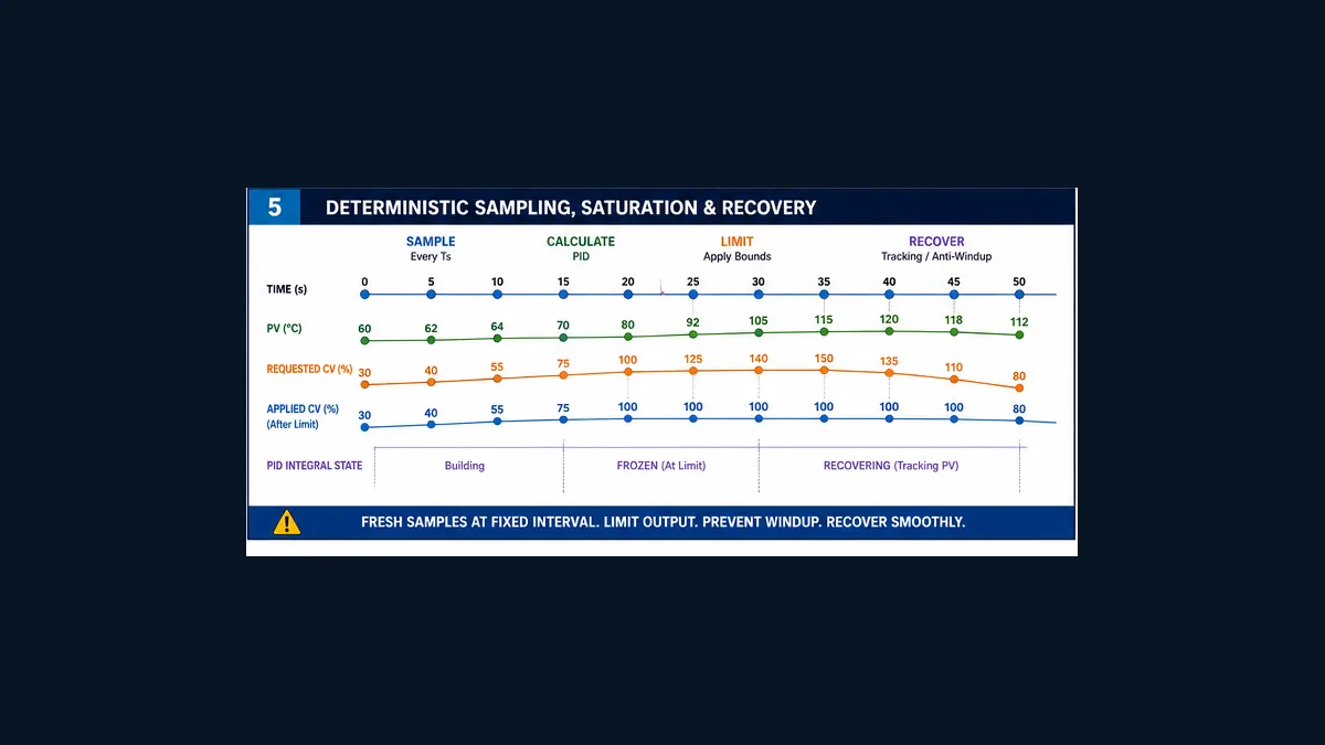
Limits, saturation and windup evidence
Define SP bounds, output bounds and any state-dependent limits independently. A warm-up state may legitimately allow a different output range from a product-hold state, but every dynamic limit requires an owner and visible reason.
Trend three output surfaces:
- requested CV: raw PID result;
- limited CV: result after high, low, rate or state constraints;
- applied CV: demand delivered after Manual/Auto selection, interlocks and output handling.
If requested CV remains at 100% while applied CV is 0%, tuning is not the first problem. Test actuator availability and interlocks. If requested and applied CV both saturate at 100% but PV cannot reach SP, investigate heater capacity, supply, losses, sensor location and operating envelope. Increasing integral action cannot create missing plant capacity.
Use Delta PID autotuning only as an authorized process test
Autotune intentionally disturbs the process to estimate behavior. It can cause output changes, temperature excursions and production loss. Confirm the exact target supports the function, read the target manual, define the safe test band, keep independent protections active, staff the test, specify abort conditions, and review proposed parameters before normal operation.
A dated Delta Industrial Automation EMEA oven article demonstrates one historical DVP example in which a control-mode location at S3 + 4 is set to K3 for auto-tuning and changes to K4 after completion. That is useful evidence that some DVP implementations have explicit modes. It is not proof that those offsets or values apply to every DVP CPU, firmware, software version, module or drive. Use them only when the exact current target manual confirms them.
An autotune checklist should answer:
| Before start | During test | After completion |
|---|---|---|
| exact CPU/path and mode verified | SP, PV and all CV surfaces trending | mode returned to intended state |
| sensor and output scaling proved | independent limits/interlocks active | calculated parameters range-reviewed |
| process at approved steady condition | operator watches abort thresholds | bounded response test completed |
| safe SP and output band signed | first-out events and saturation captured | values, software and program checksum archived |
| product/equipment consequences accepted | no unattended or production surprise | old set retained for rollback |
Do not autotune around a bad sensor, wrong control direction, output mismatch or undersized heater. It will estimate the broken system it is given.
Original oven model for offline reasoning
A simple first-order model can help explain evidence before any field test:
T_next = T + (Δt / τ) × ((T_ambient + K × CV) - T)
For an original teaching model, let ambient be 20 °C, K be 1.5 °C per percent CV, τ be 120 seconds and Δt be 1 second. At PV 65 °C and CV 42%, the steady target implied by the model is 20 + 1.5 × 42 = 83 °C; the next model sample is 65 + 1/120 × (83 - 65) = 65.15 °C.
| Quantity | Teaching value | Interpretation |
|---|---|---|
| SP | 80 °C | desired oven temperature |
| current PV | 65 °C | measured/modelled temperature |
| error | 15 °C | SP - PV for the stated convention |
| illustrative applied CV | 42% | example controller result, not derived tuning advice |
| 10 s-window on-time | 4.2 s | time-proportioning illustration |
| one-second model PV | 65.15 °C | predicted next sample under the simplified model |
This model ignores transport delay, sensor lag, nonlinear heat loss, supply variation, door opening and actuator faults. It is suitable for learning how SP, PV, CV, limits and sampling interact. It is not a plant model validated for tuning. Browser simulation should lead to better questions and tests; the real Delta target and process provide acceptance evidence.
Commission the loop in evidence order
- Review architecture: identify the single PID owner, independent protections and final-element control path.
- Verify compatibility: record CPU, firmware, software, modules and exact manuals.
- Inspect de-energized wiring: follow approved isolation and electrical procedures.
- Commission measurement: validate channel status and low/mid/high scaling.
- Prove output in Manual: test safe low/mid/high commands and feedback without PID.
- Prove direction: make an authorized small output change and observe the delayed PV response.
- Measure timing: capture PV freshness, PID interval, output/window behavior and process delay.
- Test modes: prove Manual/Auto tracking, rejected Auto and restart behavior.
- Inject faults safely: bad/stale PV, unavailable heater, limit, interlock and output mismatch.
- Apply conservative approved initial settings: verify numerical representation and action.
- Run bounded response tests: separate SP changes from load disturbances.
- Archive as-left evidence: program checksum, device map, parameters, trends, tests and deviations.
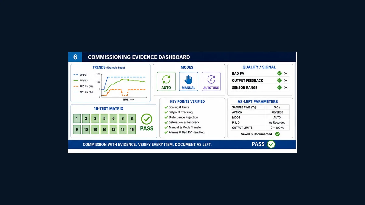
The downloadable matrix adds objective pass evidence to each stage. Fill it before the test so “looks stable” does not become the acceptance criterion.
Troubleshooting a Delta PLC PID loop
| Symptom | First evidence to compare | Likely boundary | Do not start with |
|---|---|---|---|
| PV moves opposite to expected direction | applied CV step and delayed PV response | field wiring, output inversion, process direction or action | larger gains |
| PID output never changes | mode, execution marker, SP/PV units, status and parameter block | call condition, target support or wrong parameter/mode | replacing the sensor |
| PID requests output but heater stays off | requested/limited/applied CV and availability | interlock, mode selection, output logic, wiring or final element | retuning |
| temperature oscillates | fixed sample evidence, PV noise, requested/applied CV and window switching | timing, aggressive terms, quantization, output cycling or nonlinear process | autotune without diagnosis |
| PV is stable but wrong | raw/scaled points and SP units | scaling, sensor type, offset or setpoint representation | more integral immediately |
| long saturation then overshoot | requested/limited/applied CV and recovery trace | insufficient capacity, windup, limits or long dead time | removing output limits |
| values change after download/restart | initialization order, retention and parameter writers | overlapping devices, recipe/HMI write or restart policy | random online edits |
| autotune never completes | exact mode/status, PV movement, output limits and process state | unsupported target/mode, inadequate excitation, blocking state or wrong path | copying another CPU’s offsets |
| simulator differs from PLC | instruction support, timing, special-module and I/O model | offline-simulation boundary | declaring hardware faulty |
Use a synchronized trend with SP, PV, requested CV, limited CV, applied CV, mode request/effective, PV quality, saturation, actuator availability and first-out reason. Without those channels, several different failures look like “the PID is bad.”
Frequently asked questions
What is the Delta PLC PID instruction syntax?
Many Delta DVP references use the conceptual form PID S1 S2 S3 D, where the operands represent SP, PV, a parameter-block base and the control-output destination. Verify the exact signature, legal devices, parameter span, numerical format and execution rules in the programming manual for the installed CPU and firmware.
Can I copy Delta PID D-register addresses from an online example?
No. An example address can overlap your project or refer to another CPU/manual revision. Reserve the full target-specific parameter range, name every offset, document every writer and prove no overlap with direct, indirect, HMI, recipe or initialization access.
Should PID run in the DVP CPU or DVP-04TC module?
Choose one based on the exact hardware and required architecture. CPU PID and module-internal PID have different parameter, timing and diagnostic models. If the module closes the loop, the PLC should supervise that documented path rather than unknowingly run a second controller against it.
Are ISPSoft and WPLSoft PID projects interchangeable?
Do not assume so. Record the exact editor/version and project target, follow Delta’s current compatibility guidance, and compile, transfer, monitor, restart and regression-test in the approved environment.
What sample time should a Delta PLC PID use?
There is no universal number. Use a deterministic interval supported by the exact instruction and manual, fast enough for the measured process and signal chain but not so fast that it mainly reacts to noise. Verify the actual interval under representative controller load.
How do I scale a temperature value for Delta PID?
Start with the exact module’s raw representation and engineering range. Prove low, midpoint and high inputs, preserve adequate numeric resolution and pass one documented PV representation into the PID. Do not apply the article’s hypothetical 0–4000 counts unless that is genuinely your verified module range.
Why does the Delta PID output stay at 100 percent?
Compare SP/PV units, action, output limits, requested versus applied CV, actuator availability and process capacity. Persistent saturation may mean the heater cannot meet the load or is not actually applying demand; it is not automatically a tuning problem.
How do I make Delta PID Manual-to-Auto transfer bumpless?
Define requested and effective modes, initialize the controller state from the current applied CV using the target-supported mechanism, and accept Auto only with good PV and an available actuator. Prove the output step against a signed criterion on a synchronized trend.
Can Delta PLC simulation prove a PID program?
It can help with supported logic and an external teaching model, but Delta notes that its simulator does not support every instruction. It cannot prove physical module conversion, output hardware, field direction, actuator response, independent protection or exact installed-process dynamics.
How do I use Delta PID autotuning?
First confirm exact target support and mode definitions in the current manual. Treat autotuning as a formally authorized process test with safe SP/output bands, active protections, live monitoring, abort criteria, parameter review and rollback. Never generalize a legacy S3 offset to a different CPU or module.
What does S3 + 4 = K3 and then K4 mean?
A dated Delta regional oven example uses those values for autotune and adjusted-temperature modes in its particular implementation. It is historical, target-specific evidence—not a universal Delta DVP rule. Use it only if the exact current target documentation confirms the same offset and definitions.
How do I convert a Delta PID output to a heater command?
Keep CV in documented units, constrain it, and convert the applied percentage through an electrically approved analog or time-proportioning output design. A 42% command in a 10-second teaching window is 4.2 seconds on, but the real window and switching device require engineering approval.
What signals should I trend while tuning Delta PLC PID?
Trend SP, PV, requested CV, limited CV, applied CV, requested/effective mode, PV quality, saturation, actuator availability and first-out events on one time base. Also record the program checksum, PID settings and calculation interval.
Is this Delta PID example ready for a production oven?
No. It is an engineering workflow and original teaching model. Production use requires exact hardware/manual mapping, electrical and process design, risk assessment, independent protection, field validation, authorized tuning and signed acceptance evidence.
Primary sources and further reading
- Delta Programmable Logic Controllers product family
- Delta Download Center
- Delta DVP PLC Programming Manual reference — retrieve the current target-approved revision from Delta if a direct link has moved or access is restricted.
- Delta DVP Series starter-kit manual
- Delta DVP-ES3 hardware and operation manual
- Delta FAQ: ISPSoft versus WPLSoft
- Delta FAQ: PLC simulator instruction limitations
- Delta FAQ: DVP-04TC PID function — verify current routing and the exact module manual before implementation.
- Delta Industrial Automation EMEA: PLC PID auto-tuning for temperature control — dated regional example; not a current universal register map.
- Delta Industrial Automation EMEA: PID heating and cooling — dated regional implementation context.
- ISA: PID controller fundamentals
- NIST/SEMATECH e-Handbook: process modeling
- OSHA control of hazardous energy
Use sources in this order: the exact installed product manual and approved project documentation first, current Delta support pages second, and dated regional examples only as historical context. Search-result snippets, forum posts and videos can suggest questions, but they cannot establish target compatibility or authorize a process test.
Now run it · free to start
Tune a PID loop against a live process model
Change the setpoint and loop terms, then measure overshoot, settling time and error in a browser PID lab. Free to start, nothing to install.
Ownership disclosure: PLC Programming IO and PLC Simulation Software are operated by the same publisher.
PLC Programming IO Editorial Team
Industrial automation education, references, and software testing
The PLC Programming IO Editorial Team publishes sourced industrial-automation education and documents how material is reviewed, tested, and corrected. A team byline means the publisher is responsible for the page; it does not represent a fictional person or imply an engineering licence.
Coverage:
- • PLC programming concepts and examples
- • Vendor software tutorials and comparisons
- • SCADA, HMI, protocols, and instrumentation
- • Training, careers, and reference material
Review standard:
- • Prefer primary and official sources
- • Record software versions when material
- • Separate tested facts from estimates
- • Publish material corrections
Important scope note
This site provides education, not project-specific engineering approval. Safety, code, and compliance decisions require a qualified person with access to the actual machine and jurisdiction.