Siemens LOGO! PLC Programming: Beginner Guide
Learn a verified Siemens LOGO! workflow: choose the exact controller, license LOGO! Soft Comfort, build two function-block examples, simulate faults, and commission safely.
Siemens LOGO! is a programmable logic module for small, bounded control jobs such as lighting, ventilation, simple pumps, gates and educational panels. It is not a miniature S7-1200: it has its own hardware limits, engineering workflow and software. This tutorial takes one defensible route from requirements to a simulated program and then to witnessed commissioning.
Does Siemens LOGO! support PROFINET? Treat that question as a protocol-role check, not an Ethernet-cable check. Current Siemens LOGO! documentation describes Ethernet-based LOGO!, S7 and Modbus TCP communication, web functions and generation-specific MQTT capability. Siemens's current LOGO! selection guidance says a SIMATIC controller is normally the better choice when the application requires a PROFINET IO architecture. A WinCC connection or Ethernet link that uses Siemens communication naming does not by itself make LOGO! a freely configurable PROFINET IO Controller or IO Device. Confirm the exact LOGO generation, catalog number, firmware, peer and required data-exchange role before selecting hardware.
Current-product note — reviewed July 25, 2026: Siemens's 2024 LOGO! Soft Comfort V8.4.1 online help documents the current tool family. A Siemens 2024 LOGO! application example lists LOGO! Soft Comfort V8.4 as a single-license product. Siemens separately publishes demo and update packages. Therefore, this guide does not call the full production tool a free download. Confirm the current license, demo limits, operating-system support, controller firmware and catalog numbers in your region before starting.
The examples are educational patterns, not Siemens-certified project files. They deliberately avoid model-specific I/O counts and fixed prices. Validate block behavior in the help for your installed build, simulate the abnormal cases, and test the real field wiring under the site's electrical and machine-safety procedures.
Practice the same start/stop, timer and feedback ideas in a browser-based PLC simulator. The simulator is a learning tool; it does not emulate LOGO! firmware, electrical outputs, web-server security or safety certification.

Siemens LOGO! role and fit
LOGO! sits between fixed-function relays and a general machine PLC. A base module combines power supply, digital I/O, logic execution and—on selected catalog numbers—a local display and Ethernet features. Expansion modules add compatible I/O within the limits of the selected generation.
The useful distinction is the requirement envelope:
- choose LOGO! when the logic is compact, the supported blocks cover the sequence, and the exact base/expansion combination meets the I/O and environment;
- choose a larger PLC when the project needs a richer data model, extensive diagnostics, motion, large distributed I/O, complex recipes, team-scale software architecture or a lifecycle path that LOGO! cannot meet;
- never infer a required safety integrity or performance level from ordinary LOGO! logic. Required safety functions need an approved, validated safety architecture.
Siemens product names, generations and catalog suffixes matter. Record the full catalog number, supply voltage, output type, display option, expansion modules and firmware. Two units described casually as “LOGO! 8” may not be interchangeable for a real panel.
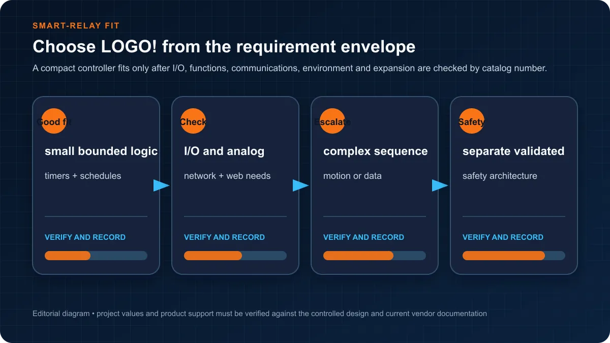
LOGO! Hardware and Fit Boundary
Build a short selection sheet before opening the programming tool:
| Requirement | Evidence to record | Why it matters |
|---|---|---|
| Supply and outputs | Exact base-module catalog number and datasheet | Prevents a DC/AC or relay/transistor mismatch |
| Inputs and analog signals | Channel type, voltage/current range and common reference | Avoids treating every terminal as the same signal type |
| Expansion | Approved module order, power budget and generation compatibility | A physical fit does not prove electrical or firmware support |
| Communications | Required peer, protocol, port and loss-of-comms response | “Has Ethernet” is not a communication design |
| Environment | Temperature, enclosure, pollution, EMC and approvals | Determines whether the controller can be installed in the area |
| Maintainability | Spare availability, backup process and local skills | A cheap controller can be expensive to recover |
Do not design around a remembered maximum I/O number. The supported module mix depends on the base device, generation and expansion rules. The current Siemens manual and catalog are the source of truth.
LOGO! versus S7-1200 selection
Use a matched proof project rather than a price slogan. Create the same I/O list, sequence, alarm list and network requirement for both candidates. Then verify:
- whether the required blocks and data fit cleanly;
- whether a technician can diagnose the expected failures;
- whether expansion and communications are supported;
- how the project is backed up and restored;
- the complete quoted cost for controller, I/O, software entitlement, panel hardware, training and support.
LOGO! often wins a small, stable task. S7-1200 becomes the better engineering choice when the apparent saving would be consumed by workarounds or a foreseeable migration.
LOGO! Soft Comfort: Install and Verify
LOGO! Soft Comfort is the desktop engineering environment used to create, simulate, document and transfer LOGO! switching programs. Treat the installer and license as controlled project dependencies.
Installation evidence checklist
- Obtain the installer, demo or update from Siemens—not a third-party mirror.
- Record the product version, service pack, file source and license entitlement.
- Check the operating system against the help or release notes for that build.
- Confirm the build supports the target LOGO! hardware and firmware.
- Create a blank project for the exact device, compile it and open simulation.
- Store the installer reference, project file and as-left backup in the controlled project repository.
Siemens's V8.4.1 help covers the editor and simulator. An update package does not by itself grant a new full license, and a demo is not proof of production entitlement. These distinctions belong in purchasing and contractor handover records.
Languages and program representation
LOGO! Soft Comfort centers on graphical switching logic. Depending on the supported device and project, the workflow uses:
- Function Block Diagram (FBD): logic, timers, counters and special functions connected as a signal flow;
- Ladder Diagram (LAD): a contact-and-coil representation familiar to relay and PLC technicians.
Do not promise Structured Text portability from LOGO! to an S7 controller. A later migration may preserve the control intent, but the project structure, blocks, addressing and diagnostics must be rebuilt and retested in the target engineering system.
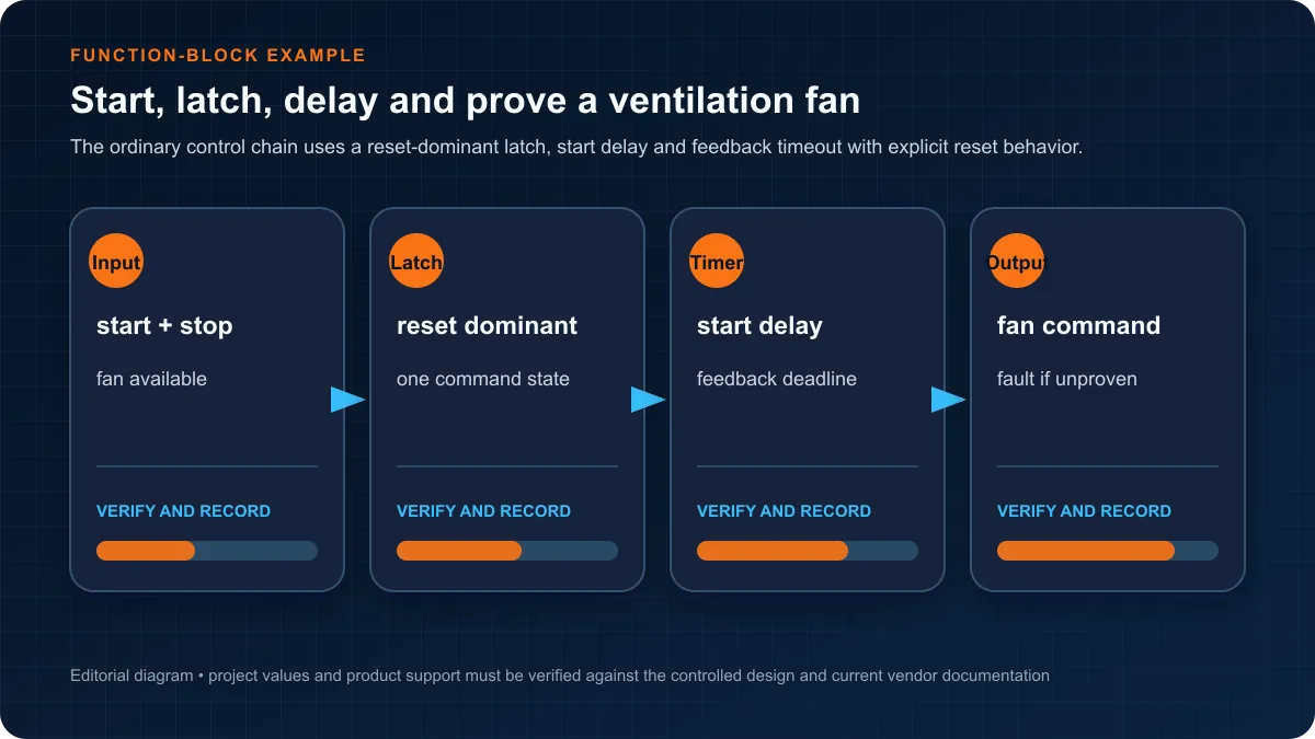
Your First Function-Block Program
Use a ventilation fan as a first program because it reveals more than a bare output coil. The educational requirement is:
- the fan may start only in Auto with a valid demand and healthy ordinary permissives;
- Stop or loss of an ordinary permissive resets the run request;
- after the command, airflow feedback must appear within an approved time;
- a failed start removes the command and latches an actionable fault;
- Reset clears the fault only after the condition is healthy.
Suggested signal contract
| Signal | Type | Meaning | Fail behavior |
|---|---|---|---|
AutoMode |
BOOL input | Automatic operation selected | False disables auto start |
FanDemand |
BOOL internal/input | Ventilation requested | False removes run request |
FreezeStatOK |
BOOL input | Ordinary process permissive healthy | False blocks/resets ordinary command |
FanRunFeedback |
BOOL input | Auxiliary/airflow proof | Missing proof triggers start failure |
FanCommand |
BOOL output | Command to interposing device | Off on stop or failed start |
FanStartFault |
BOOL internal | Start was not proven in time | Latched until approved reset |
Build order in FBD
- Combine
AutoMode,FanDemand,FreezeStatOKandNOT FanStartFaultinto the run permit. - Feed Start and Reset/Stop conditions into a reset-dominant latch.
- Drive
FanCommandfrom the latched request. - Start an on-delay timer while
FanCommandis true and feedback is false. - When the timer completes, set
FanStartFaultand reset the command. - Require a deliberate Reset and healthy permissives before another attempt.
The exact block names and input polarity must be checked in the installed LOGO! Soft Comfort help. The ordinary software chain does not replace a required hardwired or safety-rated stop function.
Simulation cases
Run a truth-table test, not just a successful start:
| Initial condition | Stimulus | Expected observation |
|---|---|---|
| Auto, healthy, no demand | Demand becomes true | Command turns on; feedback timer begins |
| Command on, no feedback | Timer reaches approved limit | Command drops; fault latches |
| Command on, feedback arrives | Feedback before limit | Timer resets/does not fault |
| Running | Stop or permissive loss | Command drops without waiting |
| Faulted | Reset with condition still bad | Restart remains blocked |
| Faulted, condition healthy | Authorized reset | Fault clears; a new request is permitted |
This test set transfers well to larger PLCs because it expresses state and evidence instead of depending on a vendor screenshot.
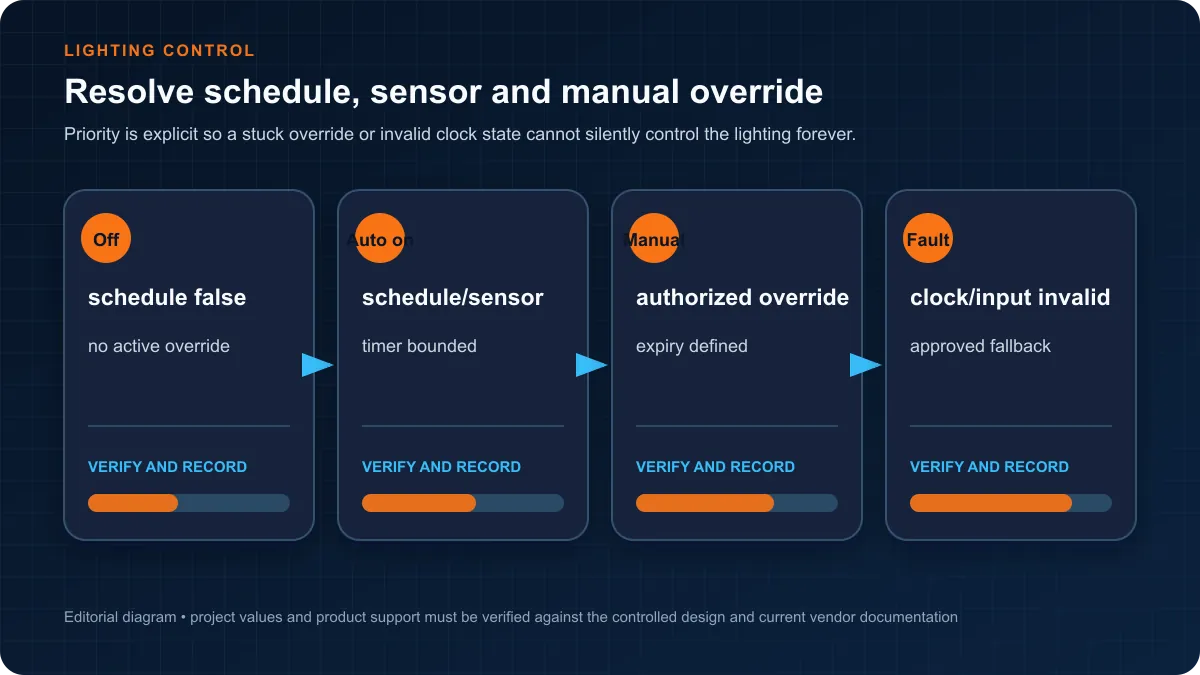
Worked Application 1: Scheduled Lighting with Override
A schedule-only lighting example is deceptively incomplete. A maintainable design must resolve schedule, occupancy sensor, manual override, time validity and restart state.
Control intent
ScheduleOnenables normal occupied-hours lighting.OccupancyPulsemay extend lighting for a bounded duration outside the schedule.ManualOverrideis authorized, visible and expires automatically unless the requirements explicitly call for a maintained override.- an invalid clock or failed time synchronization produces an approved fallback and alarm/maintenance indication;
- power restoration returns to a documented state rather than relying on an accidental retained bit.
Build the logic as explicit modes: Off, AutoOn, TimedOccupancy, ManualOverride and ClockFault. Give the override timer and occupancy timer independent reset rules. Display the active mode so a technician can explain why the lights are on.
What to test
- schedule boundary before and after midnight;
- daylight-saving or time correction behavior where applicable;
- override activation and expiry;
- repeated occupancy pulses;
- power cycle during each mode;
- invalid clock/time source;
- manual switch or output-device failure.
Do not treat an astronomical-clock block as evidence that the site latitude, time zone or daylight-saving configuration is correct. Those are commissioning data.
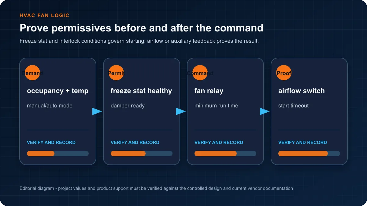
Worked Application 2: Ventilation Fan Permissives
Extend the first program into a small HVAC sequence:
- open the outside-air damper when demand is valid;
- wait for a damper-open proof or approved travel time;
- start the fan if the freeze stat, overload and maintenance inputs are healthy;
- prove airflow within the start window;
- on loss of airflow, remove the ordinary command and raise a diagnostic;
- on normal stop, apply the specified fan and damper post-run sequence.
The sequence benefits from named state bits even in a small smart relay:
| State | Output intent | Transition evidence |
|---|---|---|
Idle |
Fan off, damper in approved idle position | Demand becomes valid |
OpeningDamper |
Damper open command | Open proof or timeout |
StartingFan |
Fan command on | Airflow proof or timeout |
Running |
Fan on; monitor permissives | Demand false or fault |
Stopping |
Fan off; apply post-run | Timer complete |
Faulted |
Outputs at approved fault state | Condition healthy + authorized reset |
A compact controller can implement this bounded sequence, but every field device, output rating and motor-control interface still needs normal electrical design.
Simulation Before Hardware
LOGO! Soft Comfort simulation is useful for logical behavior:
- contact and block states;
- timer/counter transitions;
- mode selection and reset behavior;
- power-up assumptions represented in the program;
- sequence paths and impossible transitions.
It cannot prove:
- terminal wiring, voltage, commoning or input polarity;
- relay/transistor output duty and interposing-device selection;
- sensor response, mechanical travel or motor feedback;
- network latency, firewall rules or web-server exposure;
- electrical safety, machine safety or regulatory compliance.
Use simulation to find logic defects early, then use a point-to-point and functional test on the installed system.
Siemens LOGO! PROFINET compatibility
The phrase Siemens LOGO! PROFINET can describe several different requests: putting a LOGO! on the same Ethernet infrastructure as PROFINET equipment, exchanging data with an S7 controller, configuring a WinCC HMI connection, or making LOGO! act as a cyclic PROFINET IO Controller or IO Device. Those are not interchangeable capabilities.
Direct compatibility matrix
| Requested capability | What current evidence supports | Engineering decision |
|---|---|---|
| connect LOGO! to an Ethernet switch used elsewhere by PROFINET nodes | physical Ethernet coexistence may be possible when network design, addressing, load and security permit it | sharing media does not grant a PROFINET IO role |
| exchange data between LOGO! and SIMATIC S7 | Siemens documents S7 client/server communication over TCP/IP for supported LOGO generations | configure the supported S7 connection and prove addresses, direction, update and loss behavior |
| exchange registers with another controller, HMI or gateway | Siemens documents generation-specific Modbus TCP client/server functions | use the exact Modbus map, roles, unit/address notation and write permissions |
| connect a supported WinCC Unified HMI to LOGO! | Siemens documents a LOGO communication channel that can appear as PROFINET in the HMI connection editor |
treat it as the documented HMI driver path, not proof of generic PROFINET IO Controller/Device capability |
| publish selected data northbound | Siemens documents MQTT/cloud functions for specific LOGO generations | verify generation, broker security, topic/data contract, queue behavior and local independence |
| import a GSDML and configure LOGO! as arbitrary PROFINET IO Controller or IO Device | the current LOGO manuals and selection guidance do not establish this as the general LOGO engineering path | select a SIMATIC controller or an explicitly supported gateway when true PROFINET IO is mandatory |
The distinction matters because PROFINET IO engineering normally includes named IO Controller and IO Device roles, device identity, GSDML-described modules/submodules, cyclic I/O data, alarms, application relationships and update-time behavior. An RJ45 port, IP address, S7 connection or HMI driver does not supply those contracts automatically.
LOGO! 8, LOGO! 9 and installed-base boundaries
Do not transfer a capability from one generation to another. The 2022 LOGO! 8 system manual documents logical Ethernet connections for LOGO!, S7 and Modbus communication. Current Siemens product information describes generation-specific web, cloud and MQTT functions. Siemens introduced LOGO! 9 in 2026 with new hardware, engineering and security characteristics, while its current selection guidance still directs PROFINET IO architectures toward SIMATIC controllers.
Record the full base-module order number, hardware generation, firmware, LOGO! Soft Comfort version and communication peer. A tutorial for LOGO! 8.4 cannot prove a feature exists or behaves identically on an earlier 0BA8 unit, LOGO! 9, a communication module or a regional catalog variant.
Why WinCC can say PROFINET without making LOGO! an IO Device
Engineering tools sometimes name a connection by a product driver, interface family or transport path. The supported-device documentation for WinCC Unified lists PROFINET and Ethernet channels for a SIMATIC LOGO! connection and then defines tag-based data exchange. That is useful evidence for the specified HMI connection. It is not a GSDML, IO Device conformance statement or permission to configure LOGO! as a generic cyclic field device under any third-party IO Controller.
State the task in a testable sentence: “The HMI shall read these LOGO variables through the supported WinCC LOGO driver,” or “The S7-1200 shall exchange these values through an S7 connection.” Avoid “connect it over PROFINET” until the required role, engineering object and data contract are named.
Choose the supported LOGO! communication path
Protocol and service comparison
| Path | Strong fit | Required contract | First failure evidence |
|---|---|---|---|
| LOGO-to-LOGO Ethernet connection | small peer exchange among supported LOGO modules | client/server direction, address range, update rule and restart state | peer status, configured connection and known test bit |
| S7 communication over TCP/IP | bounded exchange with a supported SIMATIC controller or Siemens HMI path | connection endpoints, TSAP or tool-generated identifiers, data areas, direction and loss response | socket/session status, partner configuration and incrementing heartbeat |
| Modbus TCP | multi-vendor register exchange | client/server role, IP/port, function, zero-based offset, data type, word order, write rights and timeout | one known register read with packet and endpoint evidence |
| WinCC LOGO connection | supported operator visualization and tag exchange | exact HMI/runtime version, driver/channel, LOGO access setting, tag address and user privilege | HMI diagnostic log, tag quality and known changing value |
| MQTT/cloud path | bounded telemetry, dashboard or integration for supported generations | broker, TLS identity, topic/schema, retained/session behavior, write boundary and offline response | broker session, publish counter, timestamp/quality and queue health |
| embedded web server | local approved monitoring/configuration supported by the exact device | identity, roles, HTTPS capability, network boundary, backup and session timeout | access log, certificate/session state and denied unauthorized access |
If the task needs deterministic cyclic remote I/O, a drive telegram, PROFIsafe, device alarms or a TIA Portal PROFINET IO system, stop trying to reinterpret the LOGO Ethernet port. Select a controller and device set whose official manuals explicitly support those roles.
LOGO! to S7-1200 data-exchange workflow
- Write the data contract first: signal name, owner, type, unit, valid range, update need, write authority, stale timeout and fallback.
- Verify the exact LOGO and S7 generations support the selected S7 or Modbus TCP roles. Do not infer support from a successful ping.
- Configure fixed, owned addressing and the supported connection in LOGO! Soft Comfort and the S7 engineering environment.
- Start with one changing counter or heartbeat and one read-only process value. Prove direction and freshness before adding commands.
- For any write, use a request, sequence or acknowledgment pattern appropriate to the risk; never map an HMI button directly to an unbounded physical action.
- Disconnect the cable, stop each endpoint and power-cycle them separately. Verify stale indication, local control behavior, reconnect and duplicate/replayed request handling.
- Save screenshots, connection settings, address maps, software versions and packet or diagnostic evidence with the as-left project.
The Siemens S7 connection application example is an implementation reference for supported products, not a substitute for the current manuals or site acceptance. Exact connection capacity, data areas and access settings vary by generation and firmware.
Gateway and protocol-conversion boundary
A gateway may be appropriate when an installed LOGO! must exchange a small, bounded dataset with a PROFINET IO system. The gateway must explicitly support the selected LOGO-side protocol and the required PROFINET IO Controller or IO Device role. Define which side owns values, how data types and quality map, what becomes stale, what happens on loss of either connection, and whether any command is retained or replayed.
Do not buy a box merely labeled “PROFINET gateway.” Require a reviewed data map, supported-device/version list, GSDML where applicable, connection and update limits, diagnostics, security controls, lifecycle support and a representative failure test. Protocol conversion does not make a non-safety path safe or preserve semantics automatically.
| Requirement | Keep LOGO! with supported Ethernet exchange | Add a verified gateway | Select SIMATIC with native PROFINET IO |
|---|---|---|---|
| a few supervisory values with an S7 peer | strong candidate | usually unnecessary | consider only if broader requirements justify migration |
| documented multi-vendor register exchange | Modbus TCP may fit | useful when the PROFINET side cannot consume Modbus | strong when the system already requires a native IO Controller |
| deterministic cyclic remote I/O and device alarms | not established by ordinary LOGO networking | possible only within the gateway's proven role and limits | preferred architecture when supported by the selected CPU/devices |
| PROFIsafe or safety-rated network function | ordinary LOGO communication is not the safety function | ordinary conversion does not create a safety function | use an engineered and validated safety-capable architecture |
| future distributed I/O, drives and TIA diagnostics | workaround risk grows quickly | adds mapping and lifecycle dependencies | normally the clearer long-term fit |
Communication symptom-to-evidence matrix
| Symptom | Likely boundary | Discriminating check | Avoid |
|---|---|---|---|
| LOGO responds to ping but data never changes | wrong application protocol, role or address | verify configured S7/Modbus/HMI connection and one known changing value | calling ping proof of PROFINET or tag mapping |
| HMI shows bad quality | driver/version, LOGO access, tag address or session | read HMI diagnostics and compare exact supported-device settings | repeatedly restarting without preserving the first error |
| S7 link connects but values are shifted | data-area, byte/word or type mapping | compare a sentinel pattern and documented source/destination offsets | changing multiple maps at once |
| data freezes after an outage | stale timeout, reconnect, session or queue behavior | disconnect once, timestamp last good value and observe recovery state | displaying last value as live indefinitely |
| gateway is online on only one side | protocol-role or device-identity mismatch | inspect both independent connection states and the mapped-quality result | treating a green power LED as end-to-end proof |
| writes work but create unexpected motion | authority and command-handshake defect | disable physical actuation, trace request/acknowledge/feedback and expiration | direct writable coils with no ownership or expiry |
Web Server and Communications
Some current LOGO! catalog numbers provide Ethernet and web-related functions. “Ethernet present” does not establish a secure remote-access design.
Document:
- IP address ownership and change control;
- protocol peers, read/write direction and required ports;
- user accounts and role boundaries;
- time synchronization;
- loss-of-comms and stale-data behavior;
- backup and recovery of web content/configuration;
- how remote support is authorized, logged and revoked.
Never expose an embedded controller web interface directly to the public internet. Follow the asset owner's network segmentation and remote-access standard, and verify the exact functions of the installed generation.
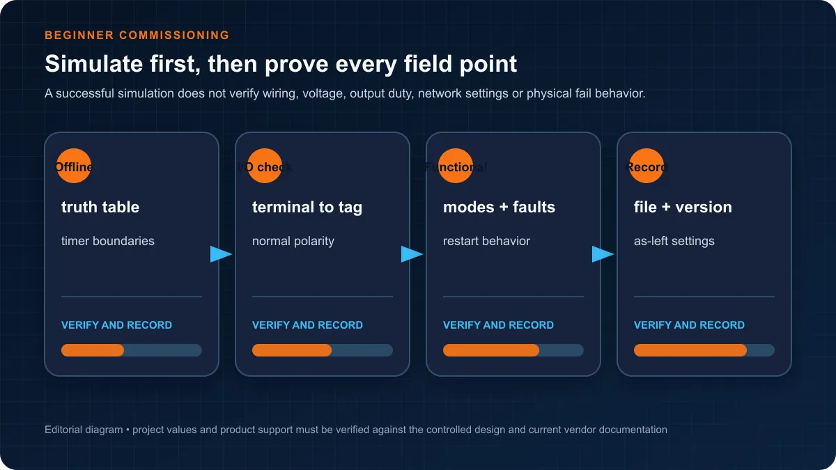
Commissioning and Evidence Checklist
Before energization
- verify catalog numbers, supply, grounding, enclosure and output interface against drawings;
- inspect terminal labels and conductor segregation;
- confirm the controlled software file, version and target hardware;
- review the cause-and-effect and the electrical/safety procedures;
- identify which tests may energize equipment and who authorizes them.
Point-to-point test
For every signal, record the drawing reference, terminal, field state, observed program state and expected polarity. Do not use software forcing as a substitute for proving the field circuit. If forcing is permitted for a controlled test, log it and remove every force before handover.
Functional test
Test each mode, permissive, timer boundary, failed start, feedback loss, power restoration and communication failure. Witness the actual physical result and alarm path. A screenshot of green logic alone is not acceptance evidence.
Handover record
- as-left LOGO! project and export/backup;
- software version and license/installer reference;
- controller and expansion catalog numbers plus firmware;
- I/O check sheets and functional-test results;
- known limitations, temporary overrides and open issues;
- recovery procedure and responsible owner.
Common Mistakes
Calling the full software free
Siemens publishes demos and updates, while official application documentation also lists a single-license LOGO! Soft Comfort product. State exactly which artifact and entitlement you used.
Selecting by a generic I/O maximum
Expansion compatibility and channel types are catalog-specific. Build the module list from the I/O schedule and verify it in current Siemens documentation.
Using an ordinary input as the safety function
PLC status from an E-stop or guard may support indication and sequence control. It does not automatically perform the required safety function.
Hiding a sequence in latch bits
Use explicit states and transition conditions. A future technician should be able to tell whether the sequence is idle, starting, running, stopping or faulted.
Assuming simulation proves commissioning
Simulation validates the modeled logic. It does not validate wiring, field physics, output loading or cybersecurity.
LOGO! Learning Path
- Build Boolean start/stop logic and a reset-dominant latch.
- Add on-delay, off-delay and pulse timing with boundary tests.
- Add counters and explicit reset rules.
- Build the lighting override state model.
- Build the fan sequence with permissive and feedback failure.
- Document an I/O contract and FAT matrix.
- Rebuild one example in an IEC PLC simulator using ladder or function blocks.
- Move to an S7-1200 when the requirement needs richer data, diagnostics and program organization.
The browser product connected to this site can help with steps 1–7 using generic training scenarios. It is intentionally not presented as Siemens hardware emulation. Open the simulator and create a free practice account.
Frequently asked questions
Does Siemens LOGO! support PROFINET IO?
Do not assume a general PROFINET IO role from the Ethernet port. Current Siemens LOGO documentation describes supported LOGO, S7, Modbus TCP, web and generation-specific MQTT communication, while current Siemens selection guidance recommends a SIMATIC controller when the application requires a PROFINET IO architecture. Verify an exact controller/device role in the manual for the selected catalog number before purchase.
Can Siemens LOGO! share an Ethernet switch with PROFINET devices?
It may share physical Ethernet infrastructure when the approved network design permits the addressing, traffic, availability and security arrangement. That only proves media coexistence. It does not make LOGO! a PROFINET IO Controller or IO Device and does not validate update time, topology, diagnostics or application data.
Why can a WinCC LOGO connection be labeled PROFINET?
WinCC supported-device documentation can name PROFINET as a communication channel for the specified SIMATIC LOGO HMI connection. Treat that as the documented HMI driver path. It is not equivalent to importing a LOGO GSDML or configuring LOGO as a generic cyclic PROFINET IO Device under another controller.
Can Siemens LOGO! communicate with an S7-1200?
Yes, supported generations can exchange bounded data through a documented S7 connection, and Modbus TCP may be another supported option. Confirm the exact LOGO/S7 versions and roles, define addresses and data ownership, start with one known changing value, and test cable loss, endpoint restart, stale state and recovery.
Should I use S7 communication or Modbus TCP with LOGO!?
Choose from peer support and the required data contract. S7 communication can fit a Siemens-to-Siemens project; Modbus TCP can fit a documented multi-vendor register exchange. Neither is automatically better. Compare role support, address mapping, data types, access control, diagnostics, connection limits, update need and loss behavior on the exact devices.
Does Siemens LOGO! have a GSDML file?
Do not plan around an assumed GSDML. A third-party catalog or old product-registry entry is not sufficient proof for the current device. If the project requires LOGO to be engineered as a PROFINET IO Device, require the exact official GSDML, supported order number, conformance statement and controller workflow before selecting it; otherwise use a supported S7/Modbus path or another controller.
Can a gateway connect LOGO! to a PROFINET IO system?
Potentially, if the gateway explicitly supports the selected LOGO-side protocol and required PROFINET IO role. Prove the complete value/type map, quality and stale behavior, update and capacity limits, diagnostics, GSDML, security, restart and command replay behavior. A generic “PROFINET gateway” label is not enough.
Does LOGO! 9 add PROFINET IO support?
Current Siemens LOGO! 9 selection guidance still identifies SIMATIC controllers as the normal choice for PROFINET IO architectures. LOGO! 9 has new engineering, visualization, connectivity and security features, but those do not justify transferring an unlisted IO Controller or IO Device role. Check the current LOGO! 9 manual and catalog for the exact required function.
When should I choose an S7-1200 instead of LOGO!?
Choose an S7-1200 or another suitable SIMATIC controller when requirements include PROFINET IO, larger distributed I/O, richer diagnostics and data structures, motion, fail-safe functions, TIA Portal engineering or a growth path that would force workarounds in LOGO. Make the choice with a matched I/O, sequence, alarm, communication and recovery proof—not price alone.
How should Siemens LOGO! communication be acceptance-tested?
Record device, firmware, software and connection settings; prove one read-only sentinel; validate every mapped type and direction; add controlled writes only with authority and acknowledgment; disconnect the network; stop and restart each endpoint; fill queues where applicable; verify stale indication, local control, reconnection and duplicate handling; then preserve the as-left map and evidence.
Official Sources and Review Boundary
- Siemens, LOGO! Soft Comfort V8.4.1 Online Help, Operating Instructions, August 2024.
- Siemens, LOGO! CIM to VPN application example, component table listing LOGO! Soft Comfort V8.4 single license, 2024.
- Siemens Industry Support, LOGO! Soft Comfort V8.4 update information, describing upgrade/update contents and supported LOGO! generations.
- Siemens, LOGO! product and selection overview, including the current LOGO!/SIMATIC and PROFINET IO boundary, reviewed August 2026.
- Siemens, LOGO! 8 System Manual, documenting generation-specific Ethernet, LOGO, S7 and Modbus communication.
- Siemens Industry Mall, LOGO! 8 product overview, describing Ethernet, S7, Modbus TCP, web and LOGO! 8.4 MQTT/cloud capabilities.
- Siemens, LOGO! Modbus TCP communication example, Entry ID 109779762.
- Siemens, LOGO! to S7 client/server connection example, Entry ID 109778776.
- Siemens, WinCC Unified communication with SIMATIC LOGO!, supported channels, connection workflow and tag exchange.
- PI, PROFINET system description, for IO Controller/Device, engineering and cyclic-data terminology.
- PI, GSDML specification overview, for device-description scope; exact files and conformance remain product-specific.
- NIST, SP 800-82 Rev. 3 Guide to Operational Technology Security, for segmentation, remote access and lifecycle security boundaries.
- CISA, Secure by Design guidance, for default-security and product-lifecycle principles; site implementation still requires system-specific review.
This page was editorially reviewed August 30, 2026. Product availability, catalog numbers, licenses and software support can change; the controlled Siemens catalog, manual and release notes for the installed system take precedence. The public search review is evidence about result intent, not proof of numeric rank or overlap. The protocol matrix does not certify a LOGO generation, gateway or production topology.


