PLC Programming Languages: IEC 61131-3 Examples (2026)
Compare Structured Text, Ladder Diagram, Function Block Diagram and SFC structuring with one matched example, vendor limits and the Edition 4 change to legacy IL.
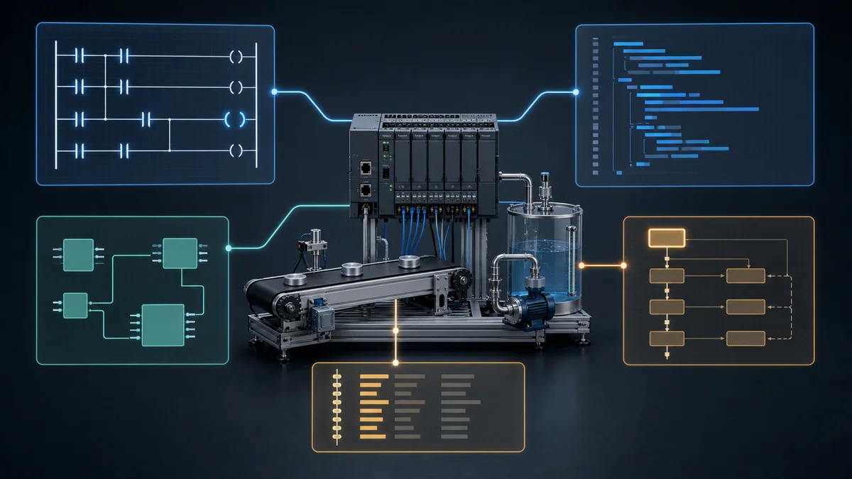
IEC 61131-3:2025 Edition 4 specifies one textual language—Structured Text (ST)—and two graphical languages: Ladder Diagram (LD) and Function Block Diagram (FBD). It also defines Sequential Function Chart (SFC) graphical and equivalent textual elements for structuring programs and function blocks. Instruction List (IL) is not included in that current suite, although vendor tools can retain legacy mnemonic languages.
For the system-level model behind these representations—field I/O, scan scheduling, program organization, software selection and commissioning boundaries—start with the PLC programming guide.
This article owns the practical PLC programming languages comparison: which representation fits a task, how equivalent examples behave, and how to test a choice. The separate IEC 61131-3 standards hub owns the standard architecture—data types, variables, program organization units (POUs), tasks, conformance and Edition 4 changes. Keeping those jobs separate makes each answer easier to verify and prevents two pages from competing for the same question.
That is more precise than the familiar “five PLC languages” shortcut:
| Current IEC 61131-3:2025 description | Practical role |
|---|---|
| Structured Text (ST) | Textual control logic, calculations, arrays and algorithms |
| Ladder Diagram (LD) | Graphical Boolean, interlock and sequence logic |
| Function Block Diagram (FBD) | Graphical signal flow and stateful block networks |
| Sequential Function Chart (SFC) elements | Organize programs/function blocks into steps, transitions and actions |
| Instruction List (IL) | Legacy vendor maintenance context; not in the Edition 4 suite |
Primary standard record—reviewed July 25, 2026: the IEC lists IEC 61131-3:2025, Edition 4, published May 22, 2025. The IEC page expressly describes ST, LD and FBD, then separately describes SFC elements. The examples below are original teaching material, not excerpts from the paid standard.
Choose Your First PLC Programming Language
Start with Ladder Diagram if your immediate goal is discrete machine troubleshooting or maintenance. Add Structured Text next because it expresses calculations, loops, arrays and reusable algorithms more clearly. Learn Function Block Diagram for signal-processing and process-control work. Learn SFC when a machine or batch is easiest to reason about as named states and transitions.
Use this decision table:
| Requirement | Strong starting representation | Why |
|---|---|---|
| Start/stop, permissives, interlocks | LD | The condition path is visible during online diagnosis |
| Scaling, formulas, arrays, recipes | ST | Text handles expressions and indexed data compactly |
| PID, analog conditioning, signal chains | FBD | Connections make data flow visible |
| Fill, mix, drain or multi-stage machine cycle | SFC elements or an explicit state machine | States, transitions and recovery paths are first-class |
| Existing mnemonic/list routine | Legacy IL or vendor mnemonic for maintenance only | Preserve behavior until a tested migration is justified |
This is a starting point, not a universal ranking. The final choice depends on the exact CPU, engineering software, safety environment, team and lifecycle.
A Matched Motor Example
The requirement:
- Start latches a run request.
- Stop removes the request.
- An overload fault prevents and stops running.
- Stop/fault must dominate Start.
- The output follows the validated run request.
Define:
| Variable | Type | Meaning |
|---|---|---|
StartPB |
BOOL | TRUE while the start command is present |
StopPB |
BOOL | TRUE while stop is requested |
OverloadFault |
BOOL | TRUE while the overload is faulted |
RunCmd |
BOOL | Internal latched run state |
MotorOut |
BOOL | Output request to the motor-control interface |
Ladder Diagram
|----[/ StopPB ]----[/ OverloadFault ]----+----[ StartPB ]----( RunCmd )----|
|                                         |                                 |
|                                         +----[ RunCmd ]--------------------|

|----[ RunCmd ]--------------------------------------------( MotorOut )-------|
Run this in the simulator — no signup
The visual branch shows the seal-in path. Stop and overload conditions surround both branches, so either removes the latch.
Structured Text
RunCmd := (StartPB OR RunCmd)
          AND NOT StopPB
          AND NOT OverloadFault;

MotorOut := RunCmd;
Run Structured Text in the simulator
The same Boolean expression is compact and easy to diff. It must still be assigned to the correct task and tested scan by scan.
Function Block Diagram
StartPB ----\
             OR ----\
RunCmd -----/        \
                      AND ---- RunCmd
NOT StopPB ----------/
NOT OverloadFault ---/

RunCmd ---------------------- MotorOut
In an actual FBD editor, use explicit NOT/OR/AND elements or the platform's documented equivalents. Feedback from RunCmd creates the latch.
SFC structuring
For a larger sequence, represent the motor command as states:
[STOPPED]
   |
   | StartPB AND NOT StopPB AND NOT OverloadFault
   v
[RUNNING]  action: RunCmd := TRUE
   |
   | StopPB OR OverloadFault
   v
[STOPPED]  action: RunCmd := FALSE
SFC is useful when this motor is one step in a machine cycle. For a two-state latch alone, LD or ST is usually simpler.
Legacy Instruction List
A vendor's old mnemonic language might resemble:
LD      StartPB
OR      RunCmd
ANDN    StopPB
ANDN    OverloadFault
ST      RunCmd
This is conceptual legacy syntax, not a portable program. Mnemonics, operand order and Boolean behavior differ by vendor. Do not create new code from this sample without the exact legacy manual.
Test the requirement, not the drawing style
Run the same tests in every representation:
| Test | Start | Stop | Fault | Expected RunCmd |
|---|---|---|---|---|
| Cold start | 0 | 0 | 0 | 0 |
| Start pulse | 1 | 0 | 0 | 1 |
| Start released | 0 | 0 | 0 | 1 |
| Stop | 0 | 1 | 0 | 0 |
| Start and Stop together | 1 | 1 | 0 | 0 |
| Start with overload | 1 | 0 | 1 | 0 |
| Overload while running | 0 | 0 | 1 | 0 |
| Fault clears | 0 | 0 | 0 | 0 until a new Start |
If two language versions do not pass the same table, they are not equivalent.

Ladder Diagram (LD)
Ladder Diagram presents logic as rungs between rails. Contacts evaluate conditions; coils or output elements write a result. Modern implementations can also contain timers, counters, arithmetic, comparisons and function blocks.
Best fit
- machine permissives and interlocks;
- start/stop and mode-selection logic;
- discrete sequences;
- logic maintained by electrical/controls technicians; and
- online troubleshooting where a visible condition path helps.
Strengths
- Boolean cause and effect is easy to inspect online.
- Relay-control experience transfers naturally.
- Contacts and coils expose permissive and interlock structure.
- Small routines can be reviewed without mentally parsing a long expression.
Failure modes
- very wide or deeply nested rungs;
- multiple writes to one output;
- hidden state spread across latch/unlatch instructions;
- calculations broken into many temporary tags; and
- using normal ladder logic as though it were a certified safety function.

Review checklist
- Can the rung be read left to right without scrolling?
- Does Stop/fault dominate Start?
- Is one tag written in multiple locations?
- Is the first-scan state defined?
- Are forces, bypasses and simulation bits visibly controlled?
- Does the online display reflect the exact task/instance being executed?
Structured Text (ST)
Structured Text is the current IEC suite's textual language. It supports assignments, expressions, conditionals, selection and iteration, plus calls to functions and stateful function blocks.
Best fit
- engineering-unit calculations and scaling;
- arrays, loops and structured data;
- recipes and data transformations;
- reusable algorithms;
- state machines; and
- logic that benefits from source-control diffs.
Example: clamp an analog command
ScaledPercent := DINT_TO_REAL(RawInput) * 100.0 / 27648.0;

IF ScaledPercent < 0.0 THEN
    ScaledPercent := 0.0;
ELSIF ScaledPercent > 100.0 THEN
    ScaledPercent := 100.0;
END_IF;
Run Structured Text in the simulator
The conversion before multiplication preserves fractional intent. The raw full-scale value is only an example; use the actual module configuration.

Failure modes
- long loops that threaten task deadlines;
- implicit numeric conversions;
- array-index errors;
- state changes hidden inside functions with unclear side effects;
- large monolithic routines; and
- code that is syntactically portable but relies on vendor libraries.
Review checklist
- Are every minimum, maximum and array bound defined?
- Are type conversions explicit?
- Is loop execution bounded?
- Are timers/function blocks instantiated and called every required scan?
- Can a technician diagnose the current state online?
- Are platform-specific functions isolated behind a clear interface?
Function Block Diagram (FBD)
FBD represents a network of functions and stateful function blocks connected by data paths. It is especially effective when the signal path is the explanation.
Best fit
- analog signal conditioning;
- PID and other control-loop structures;
- instrumentation logic;
- timers/counters connected as a functional network; and
- reusable equipment or process modules.
Function vs function block
A function normally returns a result without retaining instance state. A function block has an instance and can retain internal state between calls. A MAX calculation and a TON timer therefore have different lifecycle behavior even when both appear as rectangles.

Failure modes
- crossing lines and unreadable “spaghetti” networks;
- unclear execution order where order matters;
- reusing one stateful instance in two places;
- constants with no engineering-unit label; and
- accepting default PID/timer parameters without a test record.
Review checklist
- Does data flow consistently across the sheet?
- Is each stateful block instance unique?
- Are signal units and valid ranges visible?
- Is execution order documented when the editor does not make it obvious?
- Are enable, reset, saturation and bad-quality paths tested?
Live mini-lab
Try it: press START, then STOP
A stop-dominant seal-in rung: START latches the motor output through its own contact, and STOP breaks the circuit.
Watch the output lamp: it stays on after START until you press STOP.
Free · no signup to try · runs in your browserOpens plcsimulationsoftware.com — same team
Sequential Function Chart (SFC)
Edition 4 describes SFC as graphical and equivalent textual elements for structuring the internal organization of programs and function blocks. In practice, engineers use steps, transitions and actions to express sequences.
Best fit
- fill/mix/drain cycles;
- packaging and material-handling stages;
- startup and shutdown sequences;
- batch phases;
- parallel branches that must resynchronize; and
- equipment state models with explicit recovery.
Minimal tank sequence
[IDLE]
  Start AND permissives
       |
       v
[FILL]  Open inlet
  HighLevel
       |
       v
[MIX]   Run agitator
  MixTimer.Q
       |
       v
[DRAIN] Open outlet
  LowLevel
       |
       v
[COMPLETE]
  Reset
       |
       +------> [IDLE]
Add explicit transitions for Stop, fault, timeout and recovery. A chart that shows only the happy path is incomplete.
Failure modes
- two transitions true simultaneously without defined priority;
- no maximum time in a step;
- outputs left active after abort;
- re-entry that skips initialization;
- parallel branches that never converge; and
- state stored in both the SFC and unrelated latch bits.
Review checklist
- Is every step entry and exit condition testable?
- Does every active action turn off on abort?
- Is there a timeout and diagnostic for stalled transitions?
- Are restart and power-cycle behaviors defined?
- Can every parallel branch reach a safe convergence?
Instruction List (IL): Legacy Maintenance Context
Instruction List was a compact mnemonic representation used in many older PLC systems. IEC 61131-3:2025 does not list IL in its current language suite.
That does not automatically remove IL from installed equipment or vendor tools. When maintaining it:
- identify the exact controller, firmware and editor version;
- export and preserve the original project;
- obtain the vendor mnemonic/instruction manual;
- document accumulator and status-bit behavior;
- build an input/output equivalence test;
- migrate one bounded routine at a time; and
- retain a rollback path until the converted program passes on the target.
Do not claim that an ST translation is equivalent because it “looks the same.” Verify edge handling, numeric width, overflow, jumps, subroutine state and scan order.
PLC Language Portability Between Vendors
Concepts transfer better than projects.
The standard helps align:
- language structures;
- elementary data types;
- POU concepts;
- variable declarations;
- common functions/function blocks; and
- configuration ideas.
Actual portability is reduced by:
- proprietary instructions and libraries;
- I/O and hardware configuration;
- task scheduling;
- data-layout and conversion rules;
- retain/persistent behavior;
- communication objects;
- motion and safety systems;
- file formats; and
- firmware/version dependencies.
Even PLCopen XML exchange should be treated as a migration aid, not proof of a lossless conversion.

Vendor Support Checklist
Avoid a brand-wide “yes/no” matrix. Language support is specific to a CPU family, engineering-software edition and release.
For each target, record:
| Question | Evidence to capture |
|---|---|
| Which languages can create a Program POU? | Current programming manual/help |
| Which languages can create Functions/Function Blocks? | POU creation dialog and manual |
| Is SFC included in this software edition? | Licence/edition comparison |
| Is IL/mnemonic view legacy-only? | Migration and compatibility notes |
| Can online monitoring show every representation? | Tested screenshot/version |
| Which safety languages/elements are certified? | Safety manual and certificate scope |
| Can projects exchange XML? | Exact schema/export/import limits |
Apply that checklist separately to TIA Portal/STEP 7, Studio 5000, CODESYS, TwinCAT, GX Works, Sysmac Studio, EcoStruxure Machine Expert, Automation Builder or any other platform. A “CODESYS-based” product can still restrict languages and libraries at the target/device layer.
Selecting a Language for a Real Project
Score the candidates against the application:
- Behavior fit: Boolean/interlock, data/algorithm, signal-flow or state sequence.
- Target support: exact controller, firmware, editor and licence.
- Maintenance audience: who diagnoses it at 02:00?
- Online visibility: can they see the active condition/state?
- Testability: can the behavior be exercised automatically?
- Version control: can changes be reviewed meaningfully?
- Reuse: is the logic a tested block or copied network?
- Safety boundary: is a certified toolchain and validated library required?
- Lifecycle: can the organization maintain the chosen representation for the plant's lifetime?
The smallest number of languages that clearly expresses the system is usually easier to maintain than using every available editor.
Prove Language Equivalence Scan by Scan
Two implementations are not equivalent merely because one ladder rung and one ST statement look logically similar. A PLC program has state, execution order, task timing and instruction-specific behavior. A translation can preserve the Boolean truth table and still change the machine response at startup, during a held command, after an overflow or when a stateful block is skipped.
Start with an implementation-independent contract. For the motor example above, the contract says that Stop and overload dominate Start, a successful Start is retained, a fault clears the run request, and clearing the fault does not restart the motor. Those sentences become test cases before either language is selected. Then observe the same boundary variables at the same points in the scan.
| Equivalence checkpoint | What to compare | Common translation failure | Acceptance evidence |
|---|---|---|---|
| initialization | values on first scan, warm restart and cold restart | a retained ST variable replaces a non-retained ladder coil | restart test with declared retain policy |
| input image | value used by each implementation for the same scan | one routine reads a mapped tag after another routine changes it | timestamped scan trace or controlled input sequence |
| Boolean priority | result when Start, Stop and Fault are true together | expression grouping lets Start override Stop | full priority truth table |
| edge behavior | one-shot or transition when an input remains true | ST instruction executes every scan while ladder instruction is transitional | held-input and rising-edge tests |
| stateful blocks | timer/counter instance, call frequency and reset | a function block is conditionally skipped or one instance is reused | elapsed, done, count and reset traces |
| numeric behavior | data types, conversion, rounding, overflow and limits | implicit integer arithmetic changes a scaled result | minimum, nominal, maximum and overflow cases |
| output ownership | last writer and final mapped command | translated routine adds a second write to the same output | cross-reference plus end-of-scan value |
| task behavior | period, priority, event trigger and watchdog margin | identical code runs in a different task class | task configuration and worst-case execution record |
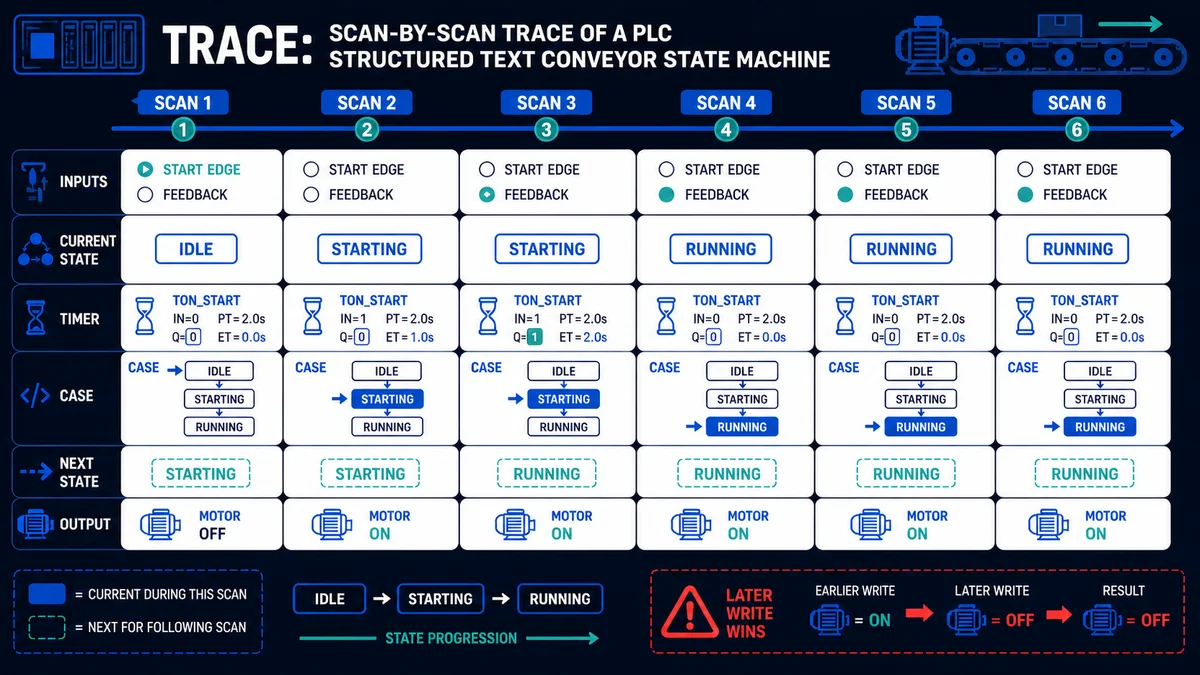
A six-scan trace for the motor latch
Assume inputs are sampled before the routine and RunCmd begins FALSE. The expected trace is independent of whether the implementation is LD, ST or FBD:
| Scan | StartPB |
StopPB |
OverloadFault |
RunCmd before |
RunCmd after |
Reason |
|---|---|---|---|---|---|---|
| 1 | 0 | 0 | 0 | 0 | 0 | no run request exists |
| 2 | 1 | 0 | 0 | 0 | 1 | Start creates the request |
| 3 | 0 | 0 | 0 | 1 | 1 | feedback path retains the request |
| 4 | 1 | 1 | 0 | 1 | 0 | Stop dominates Start and clears state |
| 5 | 1 | 0 | 1 | 0 | 0 | overload prevents a new request |
| 6 | 0 | 0 | 0 | 0 | 0 | clearing the fault does not auto-restart |
Do not use a browser model as proof of a production compiler, task scheduler, I/O module, retentive memory or safety function. Use it to expose the requirement and edge cases; repeat the acceptance table in the exact vendor tool, controller, firmware and I/O path.
Use a Language Decision Scorecard
Language debates often fail because teams argue from familiarity instead of the application. Use weighted criteria and record why a score was assigned. A scorecard does not produce a universal winner; it exposes the assumptions that would otherwise remain hidden.
Score each candidate from 1 (poor fit) to 5 (strong fit), multiply by the weight, and keep the evidence beside the number. The example below describes a discrete machine maintained by electricians, with some recipe calculations and a small step sequence.
| Criterion | Weight | LD | ST | FBD | SFC elements | Evidence question |
|---|---|---|---|---|---|---|
| online fault visibility | 5 | 5 | 3 | 4 | 4 | can the on-call team follow the active condition? |
| Boolean interlocks | 5 | 5 | 3 | 3 | 3 | does the representation expose permissive priority? |
| calculations and data | 3 | 2 | 5 | 4 | 2 | are arrays, formulas or structured data central? |
| sequence recovery | 4 | 3 | 4 | 3 | 5 | are abort, timeout and restart states explicit? |
| automated review/diff | 3 | 2 | 5 | 2 | 2 | can changes be reviewed in the current toolchain? |
| exact target support | 5 | ? | ? | ? | ? | what do the current CPU, editor and licence support? |
| team capability | 4 | ? | ? | ? | ? | who will modify this code during its service life? |
The question marks are deliberate. Do not copy a score from an article for target support or team capability. Replace them with evidence from the current product documentation, installed software and named maintainers. A platform may support a language only for certain routine or POU types; a safety task may impose a narrower set; a licence edition may omit an editor.
Choose per module, then control the boundaries
A mixed-language project can be clearer than forcing every concern into one representation. It can also become harder to navigate if state and outputs cross module boundaries without rules. Document each module's input contract, output contract, state owner, task, diagnostic surface and test suite.
| Module | Reasonable starting language | State owner | Required boundary test |
|---|---|---|---|
| field permissives and output arbitration | LD | one equipment-control routine | simultaneous request, Stop, fault and feedback-loss cases |
| analog scaling and validation | ST or FBD | signal-conditioning block instance | under-range, normal, over-range and bad-quality cases |
| recipe transformation | ST | recipe-validation function/block | type, range, missing field and version mismatch |
| machine coordinator | SFC elements or explicit ST state machine | one sequence object | every transition, timeout, abort, restart and recovery path |
| PID loop | FBD or a documented block call | unique control-block instance | manual/auto transfer, saturation, bad input and restart |
One physical output should still have one final software owner. Other modules submit requests or permissives; they should not write the mapped output independently. This rule prevents a language boundary from hiding last-writer behavior.
Verify Vendor Support Without Claiming Compliance
IEC 61131-3 alignment, PLCopen certification, import/export support and a vendor editor's available languages are different claims. Treat each independently. A product page that says “IEC 61131-3” does not prove that every language, feature, POU type or exchange path is available for every controller.
Use an evidence ladder:
- identify the exact controller or runtime, firmware, engineering-software version and licence;
- find the current vendor programming or user manual for that combination;
- confirm which editors can create each required routine or POU type;
- check task, safety, library and instruction restrictions;
- create the smallest project that exercises the required feature;
- compile it with warnings treated deliberately;
- run the acceptance cases in simulation if supported; and
- repeat hardware-dependent tests on the approved target.
| Evidence level | What it can support | What it cannot support alone |
|---|---|---|
| IEC publication record | current edition identity and described language suite | vendor implementation, licence or project portability |
| PLCopen certificate or listing | the stated compliance profile and tested version | later versions, unrestricted language support or safety suitability |
| current vendor manual/help | documented behavior for named products and versions | installed configuration or successful execution |
| compiler result | syntax, types and project checks for the selected toolchain | physical I/O, timing margin or process correctness |
| simulator/runtime test | logic behavior within the modeled runtime | exact hardware, electrical, network or safety behavior |
| target acceptance test | observed behavior of the approved installed combination | behavior after an unreviewed version or configuration change |
Vendor names are not portable language names
Vendor terminology can resemble IEC terminology without being interchangeable. Siemens SCL is the vendor's high-level textual language associated with Structured Text in its supported environments. Siemens STL is a vendor statement-list language from legacy SIMATIC families; do not assume a mnemonic-for-mnemonic mapping to IEC Instruction List or to a current target. Rockwell Logix Designer uses Ladder Diagram, Function Block Diagram, Sequential Function Chart and Structured Text editor names, but individual instructions and safety tasks can have language restrictions. CODESYS-based and TwinCAT environments can expose IEC language editors while still adding product-specific libraries, task behavior and extensions.
When migrating, map requirements and tests first, then types, data, state, instructions and task behavior. Treat vendor syntax conversion as only one part of the job.
Answer Map for PLC Language Questions
The concise answers below are designed to be independently extractable for search and AI-assisted research. Each answer links back to the verification boundary rather than pretending that one language is always best.
| Question | Direct answer | Verification boundary |
|---|---|---|
| What PLC programming languages are current in IEC 61131-3 Edition 4? | ST, LD and FBD are described as languages; SFC graphical and equivalent textual elements structure programs and function blocks. | verify against the current IEC publication record, not an undated five-language summary |
| What happened to Instruction List? | IL is not listed in the Edition 4 suite, but legacy vendor systems may still retain mnemonic editors. | check the exact controller, firmware and engineering tool |
| Is Ladder better than Structured Text? | LD is often clearer for visible Boolean paths; ST is usually more compact for data and algorithms. Neither is universally better. | test maintenance visibility and identical behavior on the target |
| Is FBD only for PID? | No. FBD can express signal conditioning, timers, logic and reusable block networks; it is especially readable when signal flow explains the design. | confirm block availability, instance lifecycle and execution order |
| Is SFC required for sequences? | No. SFC is a strong sequence representation, but an explicit, tested state machine in ST or LD can also work. | verify transition priority, timeouts, abort and restart behavior |
| Can one PLC project mix languages? | Many platforms allow different routines or POUs to use different languages. | verify target support and define state/output ownership across boundaries |
| Are IEC PLC programs portable? | Concepts and some exchange data can transfer; complete projects often depend on vendor libraries, tasks, I/O and configuration. | compile and retest in the destination toolchain and hardware |
| Which PLC language should a beginner learn? | Learn LD for Boolean control and troubleshooting, then ST for calculations and structured software; add FBD and SFC for their application strengths. | align the sequence with the platform and work you actually need |
A Practical Multi-Language Architecture
A medium machine might use:
- LD for field permissives, mode handling and output arbitration;
- ST inside reusable blocks for calculations and data handling;
- FBD for a few analog loops; and
- SFC elements or an explicit state machine for the overall sequence.
Define boundaries:
Field inputs
   ↓
Input validation and permissives (LD)
   ↓
Equipment modules / calculations (ST or FBD)
   ↓
Sequence coordinator (SFC or explicit state machine)
   ↓
Output arbitration and diagnostics (LD)
   ↓
Field outputs
No lower layer should bypass an output safety/permissive boundary merely because another language makes it convenient.
PLC Languages and Functional Safety
Programming-language choice alone does not create a safety function. Safety depends on the complete certified and validated system:
- hazard/risk assessment;
- required PL or SIL;
- safety-rated input, logic and output hardware;
- certified engineering tool and firmware combination;
- approved instructions/libraries;
- response-time calculation;
- validation tests;
- configuration control; and
- competent lifecycle management.
Use the safety manual for the selected platform. A standard LD or ST program on a normal PLC is not a safety program just because it contains an EStop tag.
Python and PLC Languages
Python is useful around a PLC—for data collection, test automation, engineering utilities, analytics and gateways. Standard CPython on a general-purpose operating system should not be assumed to meet a cyclic control deadline or safety integrity requirement.
A defensible split is:
- PLC runtime: deterministic machine/process control;
- Python or other general software: orchestration, analysis, reporting and test tooling; and
- defined interface: authenticated, bounded, failure-tested data exchange.
Some industrial platforms integrate general-purpose languages or extensions. Use their documented execution class and isolation rules; do not infer real-time behavior from the language name.
Learning Plan
Direct answer: where and how to learn the IEC 61131-3 languages
Learn them in a tool that implements the standard and run every exercise:
- CODESYS Development System: no licence fee, with LD, FBD, ST, SFC and CFC editors and a demo runtime for testing without hardware.
- OpenPLC: open source, with Windows, macOS and Linux editors.
- Beckhoff TwinCAT 3: core PLC engineering has no licence cost.
- Vendor learning material: Siemens SCE documents if you target SIMATIC SCL/LAD/FBD, for example.
- A browser simulator if you want guided lessons first. PLC Simulation Software is our product, run by the same team as this site. It has an IEC 61131-3 dialect plus vendor-style dialects, and its free tier includes the first six core lessons per dialect.
Learn in this order: ladder first, then structured text, then FBD and SFC. Write the same small requirement in two languages so you can compare them, as in the week-by-week plan below. Free options are compared in the free PLC courses list.
Week 1: Ladder Diagram
- contacts, coils and Boolean logic;
- seal-in circuit;
- Stop/fault dominance;
- TON and CTU;
- online monitoring and multiple-write checks.
Week 2: Structured Text
- variables and explicit types;
- IF/CASE;
- bounded loops;
- arrays and structures;
- function and function-block calls.
Week 3: Function Block Diagram
- signal flow;
- stateless functions vs stateful blocks;
- analog scaling;
- timer network;
- simple control loop with limits.
Week 4: Sequence Modeling
- state/step definition;
- transitions;
- abort and timeout;
- restart after fault/power loss;
- matched implementation and tests.
At each stage, rebuild the same motor and tank requirements. Repetition across representations teaches the transferable behavior.
Focused language and ladder implementation guides
Use the CODESYS Structured Text guide for project/task syntax and online debugging, the Beckhoff/CODESYS programming guide for target and runtime boundaries, and the Structured Text loops and control-flow guide for iteration, exits and scan-budget tests. For stateful reusable blocks, follow the CX-Programmer function-block guide or Siemens FB, FC and instance-DB guide. For sequence structure, use the PLC sequencer and state-machine guide. For Ladder Diagram specifically, the branches and Boolean-logic guide owns network grouping, while the online ladder simulator selection guide owns browser practice and its limits.
FAQ
How many PLC programming languages are in IEC 61131-3?
IEC 61131-3:2025 Edition 4 describes a suite consisting of ST, LD and FBD, plus SFC elements for program/function-block structuring. “Five languages” refers to older treatments that included IL and counted SFC as a language. Use the edition number when answering.
Was Instruction List removed?
IL is not listed in the Edition 4 suite. Installed vendor systems can still support legacy mnemonic code, so removal from the current IEC publication is not the same as removal from every PLC.
Is SFC a programming language?
The Edition 4 IEC product description calls SFC an additional set of graphical and equivalent textual elements for structuring programs and function blocks. In everyday engineering it is often grouped with PLC languages, but that is not the standard's precise current wording.
Which language is most common?
There is no authoritative global dataset that supports one precise market-share number across industries and regions. LD is commonly encountered in discrete machinery; ST and FBD are common where data/algorithm and process signal flow dominate. Choose for the target and maintenance team.
Which language is fastest?
Do not select by a generic language-speed claim. Compiler, runtime, task period, algorithm, libraries and target CPU determine execution. Measure the compiled project under representative worst-case load.
Should beginners learn Ladder or Structured Text?
Learn Ladder first for visual Boolean reasoning, then ST for calculations and structured software. Rebuild the same requirements in both and compare test results.
Can I mix languages in one project?
Many platforms permit different POUs in different languages. Verify the exact target, define interfaces and keep one clear owner for state/output decisions.
Are IEC programs portable?
Partly. Language concepts and some exchange formats transfer, but vendor instructions, libraries, tasks, hardware, communications and safety configuration often require manual migration and retesting.
Is Siemens SCL the same as IEC Structured Text?
SCL is Siemens terminology for its high-level textual PLC language and is associated with IEC Structured Text in supported Siemens environments. It is not evidence that a project is source-portable to another vendor: syntax versions, types, libraries, organization blocks, optimized data and runtime behavior still require documented conversion and tests.
Is Siemens STL the same as IEC Instruction List?
Do not assume they are identical. STL is Siemens vendor terminology used across legacy SIMATIC contexts, while IL is the standardized language name used in earlier IEC 61131-3 editions. Mnemonics, accumulator behavior, addresses, data widths and target support can differ. Use the exact Siemens manual and migrate by behavior tests, not by name similarity.
Primary Sources and Review Method
This page was reviewed on August 30, 2026. Claims about the current language suite use the IEC publication record; implementation guidance is deliberately framed as a verification checklist because vendor support changes by product and version. Vendor sources are examples of the evidence to collect, not a claim that every listed product supports every language on every target.
- IEC 61131-3:2025 Edition 4 publication record
- PLCopen: how to recognize an IEC 61131-3 programming system
- PLCopen: IEC 61131-3 overview
- PLCopen software construction guidelines
- PLCopen downloads: Coding Guidelines, XML exchange and SFC guidance
- PLCopen: what PLCopen certification and guidelines cover
- CODESYS current Standard library reference
- CODESYS Development System: programming languages and editors
- CODESYS Structured Text editor reference
- Siemens programming guideline for S7-1200 and S7-1500
- Siemens S7-SCL programming manual
- Rockwell Automation Logix Designer instruction-set language matrix
- Rockwell Automation Logix 5000 design considerations
- Rockwell Automation Structured Text programming manual
- Rockwell Automation ControlLogix 5590 programming-language guidance
- Beckhoff TwinCAT 3 PLC manual
- Beckhoff TwinCAT 3 IEC 61131-3 overview
- ISA-88 batch control standards overview
- PLCopen Safety overview and specifications
Practise the Same Logic in Multiple Dialects
Our related PLC Simulation Software lets learners practise control patterns across a maintained set of vendor-oriented learning dialects. Its versioned product facts document the current dialect list, lesson allowance, free-account policy, and limitations.
Disclosure and limit: plcprogramming.io and PLC Simulation Software share the same publisher. The product teaches transferable control logic and vendor-style notation; it is not a vendor compiler, firmware or safety simulator. Rebuild and validate production code in the exact target toolchain.
Continue learning:
Now run it · free · no signup
Run Structured Text in your browser
See IEC 61131-3 Structured Text execute and drive real outputs, then run a first program yourself. Free, nothing to install, no signup to try it.
Ownership disclosure: PLC Programming IO and PLC Simulation Software are operated by the same publisher.