RSLogix 5000 PLC Tutorial: Studio 5000 Setup & Logic
Create, verify, download and diagnose a ControlLogix or CompactLogix PLC project, with exact revision matching, I/O, tags, tasks, routines and controlled changes.
RSLogix 5000 was renamed Studio 5000 Logix Designer beginning with Rockwell’s version 21 release. To start a current project, select the exact supported ControlLogix or CompactLogix controller and revision, configure modules, organize execution as tasks → programs → routines, create scoped tags, verify the controller, then connect and download under an approved commissioning procedure.
Use the PLC programming guide for the transferable I/O, scan-cycle, language and testing model, then use this tutorial for the Logix-specific task, program, routine and tag implementation.
Current version and compatibility boundary
- Rockwell's public release notes list Studio 5000 Logix Designer v38.00.00, released in September 2025.
- Controller firmware and Logix Designer must use the same supported major revision—for example, firmware 38.xxx with Logix Designer v38.
- Controller, module, operating-system and companion-software compatibility must be checked in Rockwell's Product Compatibility and Download Center.
- “RSLogix 5000” remains a useful term for older projects, but this guide uses “Logix Designer” for the current application.
| Name or artifact | What it means | Do not assume |
|---|---|---|
| RSLogix 5000 | Product name used before the version 21 rebrand; still common in searches and older project environments | It is RSLogix 500 for SLC/MicroLogix, or that an old project opens in any current revision |
| Studio 5000 | Rockwell engineering environment containing Logix Designer and other applications | Every Studio 5000 edition installs every application, emulator or controller revision |
| Studio 5000 Logix Designer | Current programming application for supported Logix 5000-family controllers | One installed major revision can download to every controller firmware revision |
.ACD project |
Native project archive for a particular Logix project/revision context | The file name proves target controller identity or is a transparent text diff |
.L5K / .L5X export |
Text-based project/component exchange formats with documented schemas and limits | Import is a lossless substitute for versioned native backups and verification |
RSLogix 500 .RSS project |
Different product/controller lineage associated with supported SLC 500 and MicroLogix projects | Studio 5000 directly programs that controller merely because ladder syntax looks familiar |
Rockwell’s current design reference explicitly uses “Studio 5000 Logix Designer version 21 or later” and “RSLogix 5000 version 16 or later” for the same Logix 5000 controller design lineage. Project conversion, controller firmware support, add-on profiles, safety signatures, motion and companion software still require version-specific checks.
First project workflow
| Step | Action | Evidence |
|---|---|---|
| 1 | Record controller catalog number and firmware revision | Nameplate/online identity matches the project |
| 2 | Create controller, chassis and module tree | Catalog numbers, revisions and electronic-keying decisions are reviewed |
| 3 | Create a periodic or continuous task deliberately | Execution period, priority and watchdog are documented |
| 4 | Create program, main routine and scoped tags | Cross-reference confirms the intended owner |
| 5 | Write and verify one motor/equipment routine | Start, stop, permissive, feedback timeout and reset tests pass |
| 6 | Establish the approved communication path and compare target | Correct controller and process area are confirmed |
| 7 | Download or make an approved online change | Backup, rollback and post-change test record are complete |

Table of Contents
- RSLogix 5000 Overview and Installation
- Project Creation and Controller Setup
- Tag-Based Programming Architecture
- Programming Environment Navigation
- Ladder Logic Programming
- Function Block Diagram Programming
- Structured Text Programming
- Add-On Instructions Development
- Online Operations and Debugging
- Practical Programming Examples
- Best Practices and Troubleshooting
RSLogix 5000 Overview and Installation
Studio 5000 Logix Designer is Rockwell Automation's engineering application for supported Logix controllers. Older projects may identify it as RSLogix 5000.
Key Features and Capabilities
Tag-Based Programming: RSLogix 5000 uses descriptive tag names instead of traditional address-based programming, making programs more intuitive and maintainable. Tags can be simple data types or complex structures containing multiple data elements.
Routine editors: Supported Logix controllers and licences can use Ladder Diagram, Function Block Diagram, Structured Text and Sequential Function Chart routines. Instruction List is not a Logix Designer routine type. Support also varies for safety programs and controller families—for example, Rockwell's current ControlLogix 5590 safety manual limits safety routines to Ladder Diagram.
Advanced Features:
- Task-based program organization with different execution priorities
- Comprehensive online editing capabilities during operation
- Powerful simulation and debugging tools
- Motion control integration with coordinated system architecture
- Communication and networking capabilities
System Requirements
For v38, Rockwell's release notes list a minimum of four logical CPU cores, 8 GB RAM and 30 GB free disk space, with higher recommendations for production engineering. Supported Windows editions and compatible FactoryTalk/communication components can change by release. Use the v38 release notes and PCDC for the exact installation instead of an evergreen checklist copied from an older version.
Installation Process
Software Installation:
- Download Studio 5000 Logix Designer from Rockwell Automation website
- Run installer with administrative privileges
- Accept license agreement and select installation components
- Configure FactoryTalk activation for licensing
- Install the supported FactoryTalk Linx/communication components required by the release
- Restart computer and verify installation
Licensing Configuration: Studio 5000 uses FactoryTalk activation for software licensing:
- Node-locked activations for single computer use
- Portable activations for laptop installations
- Network activations for shared license management
- Trial activations for evaluation purposes
Project Creation and Controller Setup
RSLogix 5000 projects organize all program elements, configuration data, and documentation in integrated project files that maintain relationships between system components.

Creating New Projects
Project Setup Wizard:
- Launch RSLogix 5000 and select "New" from File menu
- Choose controller type (ControlLogix or CompactLogix)
- Select specific controller catalog number and revision
- Configure project name and storage location
- Set project properties and documentation standards
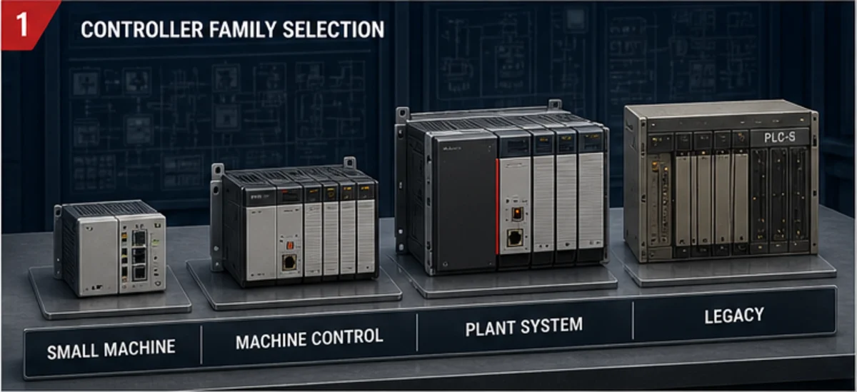
Controller selection: use the current Rockwell selection and lifecycle information. CPU family alone does not establish tasks, motion, safety, memory, network capacity or supported revision. Freeze the exact catalog number and firmware before creating the project.
| Project gate | Evidence to record | Block download when |
|---|---|---|
| Controller identity | Catalog number, series, online name, chassis/slot or network path | Online target differs from released project or work order |
| Controller firmware/application revision | Controller major/minor firmware and installed Logix Designer major revision | Supported major-revision pairing is absent or conversion is unreviewed |
| Module profile | Exact catalog, revision, slot/address, electronic keying, connection and RPI | Generic module, wrong keying or missing Add-On Profile changes the interface |
| Safety boundary | Standard versus GuardLogix/safety application, signatures and authorized workflow | Change requires safety authorization, signature handling or validated tools not in scope |
| Motion/process features | Axes, coordinated motion, process instructions, licences and controller support | Example logic depends on unsupported instruction or configuration |
| Network ownership | Controller address, route, switch/VLAN boundary and allowed engineering path | Route reaches an ambiguous or production target outside the approved change |
| Backup and rollback | Verified upload/native archive, revision, comparison and recovery procedure | Current controller state or rollback path has not been preserved |
I/O Configuration
Adding I/O Modules:
- Right-click controller in project tree
- Select "New Module" from context menu
- Choose module type from catalog browser
- Configure module parameters and communication settings
- Create tag assignments for module data
Digital I/O Configuration: Configure input and output modules with proper electrical specifications:
- Input modules: voltage levels, filtering, and update rates
- Output modules: voltage/current ratings and protection features
- Point-to-point wiring verification and documentation
Analog I/O Setup: Configure analog modules for measurement and control:
- Input scaling and engineering units conversion
- Output ranges and calibration parameters
- Filter settings for noise immunity
- Alarm and diagnostic configurations
Communication Setup
Network Configuration:
- Configure controller Ethernet settings
- Set up EtherNet/IP communication parameters
- Define network paths for remote I/O
- Configure producer/consumer connections for data exchange
- Set up diagnostic and status monitoring
Engineering communication: Use the communication software supported by the installed Studio 5000 release:
- Create Ethernet driver for controller communication
- Configure the approved path and network settings
- Test communication path to controller
- Confirm target identity before any upload, download or online edit
Tag-Based Programming Architecture
Logix controllers use named tags and structured data rather than a fixed user memory-address map.
Understanding Tags
Tag Fundamentals: Tags represent data elements in the controller with meaningful names that describe their function. Unlike address-based systems, tags provide intuitive programming and maintenance advantages.
Tag Types:
- Base Tags: Fundamental data storage elements
- Alias Tags: Alternative names pointing to other tags
- Consumed Tags: Data received from other controllers
- Produced Tags: Data transmitted to other controllers
Tag Scope:
- Controller Tags: Available throughout entire project
- Program Tags: Local to specific program organization
- Routine-local data/parameters: Availability and behaviour depend on the Logix Designer/controller version; verify before using them as an interface
Tag contract checklist
| Decision | Rule |
|---|---|
| Scope | Use the narrowest scope that still serves all deliberate consumers |
| Owner | One routine/module owns each command or state; avoid multiple writers |
| External access | Expose only tags required by HMI/SCADA/OPC UA integrations |
| Units | Put engineering units and valid range in the description/interface |
| Produced/consumed data | Add freshness, connection status and restart semantics |
| Alias | Use for a deliberate hardware/interface mapping, not to hide unclear ownership |
| Change | Search cross-references before renaming or altering a UDT member |
Data Types
Elementary Data Types:
- BOOL: Single bit Boolean values (TRUE/FALSE)
- SINT: 8-bit signed integer (-128 to 127)
- INT: 16-bit signed integer (-32,768 to 32,767)
- DINT: 32-bit signed integer (-2,147,483,648 to 2,147,483,647)
- REAL: 32-bit floating point numbers
String Data Types:
- STRING: Variable-length character strings (up to 82 characters)
- STRING[n]: Fixed-length character strings
Advanced Data Types:
- Arrays: Multiple elements of same data type
- User-Defined Data Types (UDT): Custom structured data
- Add-On Instruction Data Types: Parameters for custom instructions
User-Defined Data Types (UDT)
Creating UDTs:
- Right-click "Data Types" in project tree
- Select "New Data Type" from menu
- Define UDT structure with member elements
- Set default values and descriptions
- Save and apply UDT to project
UDT Example - Motor Control:
Motor_Control_UDT:
  Command : STRUCT
    Start : BOOL;
    Stop : BOOL;
    Jog : BOOL;
  END_STRUCT;

  Status : STRUCT
    Running : BOOL;
    Fault : BOOL;
    Aux_Contact : BOOL;
  END_STRUCT;

  Parameters : STRUCT
    Start_Delay : DINT;
    Jog_Time : DINT;
    Fault_Reset : BOOL;
  END_STRUCT;
Programming Environment Navigation
RSLogix 5000 provides comprehensive programming tools with intuitive navigation and powerful editing capabilities for efficient program development.
Main Interface Components
Project Organizer: Hierarchical tree structure displaying all project elements:
- Controller folder containing hardware configuration
- Tasks folder organizing program execution
- Programs folder containing program logic
- Data Types folder with UDT definitions
- Add-On Instructions folder for custom instructions
Programming Windows: Multiple tabbed windows for different programming languages:
- Ladder Logic Editor with graphical programming
- Function Block Diagram Editor for process control
- Structured Text Editor for algorithmic programming
- Sequential Function Chart Editor for state machines
Properties Windows: Context-sensitive property displays for selected objects:
- Tag properties showing data type and scope
- Instruction properties with parameter configuration
- Routine properties defining programming language
- Module properties for I/O configuration
Program Organization
Task Management: RSLogix 5000 organizes programs using tasks with different execution characteristics:
- Continuous Task: Background execution for non-critical programs
- Periodic Tasks: Time-based execution for real-time control
- Event Tasks: Triggered execution for interrupt processing
Program Structure: Programs contain routines written in different programming languages:
- Main Routine: Primary program logic (typically ladder logic)
- Subroutines: Called functions for modular programming
- Fault Routine: Error handling and recovery logic
- Power-Up Routine: Initialization code executed at startup
Ladder Logic Programming
Ladder Logic in RSLogix 5000 provides enhanced functionality beyond traditional relay logic with powerful instructions and tag-based addressing.

Basic Ladder Logic Instructions
Contact and Coil Instructions:
- XIC (Examine if Closed): Tests if bit is set (TRUE)
- XIO (Examine if Open): Tests if bit is clear (FALSE)
- OTE (Output Energize): Sets bit based on rung logic
- OTL (Output Latch): Sets bit and maintains state
- OTU (Output Unlatch): Clears latched bit
Programming Example - Basic Motor Control:
Rung 1: Command output from an already-arbitrated request
XIC(Motor_Run_Request) XIC(Permissives_OK) XIO(Motor_Fault) OTE(Motor_Output_Command);

Rung 2: Running indication comes from field feedback
XIC(Motor_Running_Feedback) OTE(Run_Light);
This is a teaching sketch, not a complete motor module. Generate Motor_Run_Request from a documented mode/start-stop state, define input polarity, supervise contactor/drive feedback with a timeout, latch the first fault and require an intentional reset. A safety stop must not depend on this standard OTE rung.
Timer Instructions:
- TON (Timer On-Delay): Delay before output activation
- TOF (Timer Off-Delay): Delay before output deactivation
- RTO (Retentive Timer On): Accumulates time across power cycles
Timer Programming Example:
Rung 3: Start Delay Timer
XIC(Start_Request) TON(Start_Timer, 5000, 0);

Rung 4: Delayed Start Output
XIC(Start_Timer.DN) XIC(Safety_OK) OTE(Motor_Enable);
Counter Instructions:
- CTU (Count Up): Increments counter value
- CTD (Count Down): Decrements counter value
- RES (Reset): Resets timer or counter values
| Instruction/data boundary | Meaning to prove | Common failure | Minimum acceptance test |
|---|---|---|---|
XIC / XIO |
Tests Boolean truth/falsehood; mnemonic does not prove physical normally-open/normally-closed wiring | Maintainer infers electrical polarity from the instruction name | Toggle or simulate the raw input safely and record the interpreted equipment state |
OTE |
Writes its Boolean operand from rung continuity when the routine executes | Multiple writers or a skipped routine make ownership unclear | Cross-reference all writers and test false/true/false scan behavior |
OTL / OTU |
Separate instructions set and clear retained state | Reset path is unreachable or different operating modes fight over state | Exercise set, power/restart/retentivity requirement, reset and fault recovery |
TON / TOF / RTO |
Timer structure exposes enable, timing, done, preset and accumulated state according to instruction behavior | Time base, retained accumulation or reset assumption is wrong | Test just below, at and above the preset plus interrupted and restarted inputs |
CTU / CTD / RES |
Counts qualifying false-to-true transitions and manages counter structure state | Held input is expected to count every scan, or reset affects another owner | Apply separated pulses, held input, simultaneous condition and reset boundary |
COP / CPS / FLL |
Moves or fills data using documented element/length and atomicity behavior | Length or destination type overwrites adjacent data or exposes inconsistent data | Use bounded asymmetric patterns and verify destination limits and concurrent access |
Instruction mnemonics transfer poorly when isolated from task execution, tag ownership, data type and controller revision. Verify the real routine in the exact project; do not paste a teaching sketch into a live controller.
Advanced Ladder Logic Features
Mathematical Operations: RSLogix 5000 provides comprehensive mathematical functions:
- Basic arithmetic: ADD, SUB, MUL, DIV
- Advanced functions: SQR, SQRT, SIN, COS, TAN
- Comparison operations: EQU, NEQ, GRT, LES, GEQ, LEQ
Data Handling:
- MOV (Move): Copy data between tags
- COP (Copy File): Copy arrays or data structures
- FLL (Fill File): Initialize arrays with values
- AVE (Average File): Calculate array average
Program Flow Control:
- JMP (Jump): Conditional program flow control
- JSR (Jump to Subroutine): Call other routines
- RET (Return): Return from subroutine
- MCR (Master Control Reset): Enable/disable rung execution
Program Control Example:
Rung 5: Conditional Subroutine Call
XIC(Process_Ready) JSR(Temperature_Control_Routine);

Rung 6: Emergency Shutdown Jump
XIC(Emergency_Stop) JMP(Shutdown_Label);
Function Block Diagram Programming
Function Block Diagram (FBD) programming in RSLogix 5000 excels in analog control, mathematical operations, and process control applications.
Basic Function Block Elements
Logic Operations:
- AND, OR, NOT, XOR: Boolean logic functions
- SR, RS: Set/Reset latch functions
- ONESHOT: Edge detection functions
- SEL: Select between multiple inputs
Arithmetic Operations:
- ADD, SUB, MUL, DIV: Basic arithmetic functions
- ABS, NEG, SQR, SQRT: Advanced mathematical functions
- MIN, MAX, LIM: Limit and selection functions
Process Control Functions:
- PID: Proportional-Integral-Derivative control
- PIDE: Enhanced PID with additional features
- LEAD_LAG: Lead-lag compensation
- SCALE: Linear scaling function
FBD Programming Example - Temperature Control:
Temperature Control Network:
[Setpoint] ----[SUB]----[PID]----[SCALE]----[Heater_Output]
[Process_Value]--|      |
                 |      |----[Control_Error]
[Manual_Mode] ---|
[Manual_Value]---|
Advanced Function Block Applications
Signal Processing:
- HPF, LPF: High-pass and low-pass filtering
- DERV: Derivative function for rate calculations
- INTG: Integration function for totalizing
- SWCH: Switch between signal sources
Control Algorithms: Function blocks enable sophisticated control strategies:
- Cascade control with multiple PID loops
- Feed-forward control compensation
- Ratio control for blending applications
- Override control for safety limits
Structured Text Programming
Structured Text (ST) provides high-level programming capabilities for complex algorithms, mathematical calculations, and data processing applications.

Basic Structured Text Syntax
Variable Declarations: Structured Text uses explicit variable declarations:
VAR
    Temperature : REAL;
    Pressure : REAL;
    Flow_Rate : REAL;
    Control_Output : REAL;
END_VAR
Basic Statements:
- Assignment statements: Variable := Expression;
- IF-THEN-ELSE: Conditional execution
- FOR loops: Counted repetition
- WHILE loops: Conditional repetition
- CASE statements: Multi-way branching
Programming Example - Process Control:
// Temperature Control Algorithm
IF Process_Enable AND NOT Emergency_Stop THEN
    Temperature_Error := Setpoint - Process_Temperature;

    IF ABS(Temperature_Error) > Deadband THEN
        Control_Output := Kp * Temperature_Error +
                         Ki * Temperature_Integral +
                         Kd * (Temperature_Error - Previous_Error);

        // Limit output range
        IF Control_Output > 100.0 THEN
            Control_Output := 100.0;
        ELSIF Control_Output < 0.0 THEN
            Control_Output := 0.0;
        END_IF;

        Temperature_Integral := Temperature_Integral + Temperature_Error;
        Previous_Error := Temperature_Error;
    END_IF;
ELSE
    Control_Output := 0.0;
    Temperature_Integral := 0.0;
END_IF;
Advanced Structured Text Features
Array Processing:
// Array Initialization and Processing
FOR i := 0 TO 9 DO
    Process_Data[i] := Raw_Input[i] * Scale_Factor + Offset;

    IF Process_Data[i] > High_Alarm_Limit THEN
        Alarm_Status[i] := TRUE;
    ELSIF Process_Data[i] < Low_Alarm_Limit THEN
        Alarm_Status[i] := TRUE;
    ELSE
        Alarm_Status[i] := FALSE;
    END_IF;
END_FOR;
Function Development: Create custom functions using Structured Text:
// Custom Function - Average Calculation
FUNCTION Calculate_Average : REAL
VAR_INPUT
    Data_Array : ARRAY[0..9] OF REAL;
    Array_Size : DINT;
END_VAR

VAR
    Sum : REAL;
    i : DINT;
END_VAR

Sum := 0.0;
FOR i := 0 TO (Array_Size - 1) DO
    Sum := Sum + Data_Array[i];
END_FOR;

Calculate_Average := Sum / Array_Size;
Add-On Instructions Development
Add-On Instructions (AOIs) enable creation of custom, reusable instruction blocks that extend RSLogix 5000's instruction set with application-specific functionality.
Creating Add-On Instructions
AOI Development Process:
- Right-click "Add-On Instructions" in project tree
- Select "New Add-On Instruction" from menu
- Define instruction name and revision information
- Configure input, output, and local parameters
- Program instruction logic using any programming language
- Test and validate instruction functionality
Parameter Types:
- Input Parameters: Values passed into the instruction
- Output Parameters: Results returned from instruction
- InOut Parameters: Values modified by instruction
- Local Tags: Internal variables within instruction
AOI Programming Example
Motor Control Add-On Instruction:
Motor_Control_AOI Parameters:
Input:
  Start_Command : BOOL;
  Stop_Command : BOOL;
  Reset_Command : BOOL;

Output:
  Motor_Running : BOOL;
  Motor_Fault : BOOL;
  Ready_To_Start : BOOL;

InOut:
  Motor_Data : Motor_UDT;

Logic (Ladder Logic):
Rung 1: Motor Start Logic
XIC(Start_Command) XIO(Stop_Command) XIC(Ready_To_Start)
XIO(Motor_Fault) OTE(Motor_Running);
XIC(Motor_Running)

Rung 2: Fault Detection
XIC(Motor_Data.Overload_Contact) XIC(Motor_Running) OTE(Motor_Fault);

Rung 3: Fault Reset
XIC(Reset_Command) XIO(Motor_Running) OTU(Motor_Fault);
Using AOIs in Programs:
Rung 1: Pump #1 Control
Motor_Control_AOI(Pump1_Data, Start_Pump1, Stop_Pump1,
                  Reset_Pump1, Pump1_Running, Pump1_Fault,
                  Pump1_Ready);

Rung 2: Pump #2 Control
Motor_Control_AOI(Pump2_Data, Start_Pump2, Stop_Pump2,
                  Reset_Pump2, Pump2_Running, Pump2_Fault,
                  Pump2_Ready);
Online Operations and Debugging
RSLogix 5000 provides comprehensive online capabilities for program download, monitoring, debugging, and system commissioning.
Controller Connection and Operations
Establishing Communication:
- Use the communication component supported by the Studio 5000 release.
- Browse the approved path and compare the controller identity/revision with the project.
- Determine whether the operation is an upload, full download or controlled online edit; these are not interchangeable.
- Confirm backup, process state, personnel authorization and rollback.
- Verify/accept/test/assemble online edits only under the site's change procedure.
- Return the controller to the authorized mode and run the post-change acceptance tests.
| Operation | Direction/effect | Use only when | Evidence before completion |
|---|---|---|---|
| Upload | Reads controller project/state into the workstation context | Target identity is confirmed and the current controller state must be preserved/compared | Archived upload, controller identity, revision and comparison result |
| Download | Replaces controller project/configuration from the offline project and can affect execution/I/O | Full change is authorized, machine state is controlled and rollback/recovery is ready | Verified project, backup, target comparison, mode/energy plan and post-download test |
| Online edit | Changes supported logic while connected through the pending/accepted/tested/assembled workflow | Exact edit is reviewed and process consequence is bounded | Before/after rung/component, edit states, tester, timestamps and functional result |
| Tag/data change | Alters controller data without necessarily changing logic | Owner, allowable range, persistence and process consequence are known | Old value, requested value, result and restoration requirement |
| Force | Overrides normal I/O relationship until removed/disabled according to force behavior | Site force procedure, risk controls, owner and observation are active | Force register, visible force state, removal and independent all-forces-clear check |
| Firmware change | Changes controller operating firmware and may alter compatibility/state | Vendor procedure, power/recovery, compatible application and full revalidation are approved | Firmware package/source, controller backup, compatibility record and recovery test |
Program Monitoring and Debugging
Online Monitoring: Monitor program execution in real-time:
- Tag values update continuously during program execution
- Ladder logic shows rung states and power flow
- Function blocks display input/output values
- Structured text highlights active statements
Force Functions: Forces override the normal relationship between logic and I/O and can move equipment. Use them only under an approved, risk-controlled test procedure; identify every affected output, maintain a force register and remove/verify all forces before handover. Never force safety tags or use forcing to defeat a safeguard.
Trending and Data Collection:
- Built-in trending for real-time data visualization
- Historical data collection and analysis
- Export trend data for external analysis
- Configure trend triggers and conditions
Diagnostic Tools
Controller Diagnostics:
- Processor status and health monitoring
- Memory utilization and performance metrics
- Communication status and error tracking
- I/O module diagnostics and status
Program Diagnostics:
- Scan time monitoring and optimization
- Task execution timing and priority
- Routine execution statistics
- Tag usage and memory allocation
Practical Programming Examples
Real-world examples demonstrate RSLogix 5000 capabilities and provide templates for common industrial applications.
Example 1: Conveyor System Control
Application Requirements:
- Variable speed conveyor with VFD control
- Product detection and counting
- Batch processing capabilities
- Emergency stop integration
Tag Definitions:
Conveyor_System_UDT:
  Commands:
    Start : BOOL;
    Stop : BOOL;
    Safety_Permissive : BOOL;
    Reset : BOOL;
  Status:
    Running : BOOL;
    Fault : BOOL;
    Product_Count : DINT;
    Batch_Complete : BOOL;
  Parameters:
    Speed_Setpoint : REAL;
    Batch_Size : DINT;
    Conveyor_Length : REAL;
Ladder Logic Program:
Rung 1: Conveyor Start/Stop Control
XIC(Conveyor.Commands.Start) XIO(Conveyor.Commands.Stop)
XIC(Conveyor.Commands.Safety_Permissive) XIO(Conveyor.Status.Fault)
OTE(Conveyor.Status.Running);

Rung 2: VFD Speed Control
MOV(Conveyor.Parameters.Speed_Setpoint, VFD_Speed_Command);

Rung 3: Product Counting
ONS(Product_Photoeye) CTU(Product_Counter, Conveyor.Parameters.Batch_Size, 0);
MOV(Product_Counter.ACC, Conveyor.Status.Product_Count);

Rung 4: Batch Complete Logic
XIC(Product_Counter.DN) OTE(Conveyor.Status.Batch_Complete);
XIC(Conveyor.Status.Batch_Complete) RES(Product_Counter);
Safety_Permissive is only a standard-logic status consumed from the validated safety system. This example does not implement emergency-stop or functional-safety logic.

Example 2: Temperature Control System
Structured Text Implementation:
// Multi-Zone Temperature Control
FOR Zone := 1 TO Number_Of_Zones DO
    // Read temperature input
    Temperature_PV[Zone] := Analog_Input[Zone].ScaledValue;

    // PID control calculation
    IF Temperature_Control[Zone].Auto_Mode THEN
        PIDE(Temperature_Control[Zone].PID_Config,
             Temperature_SP[Zone],
             Temperature_PV[Zone],
             Temperature_Control[Zone].CV_Percent,
             Temperature_Control[Zone].PID_Status);
    ELSE
        Temperature_Control[Zone].CV_Percent :=
            Temperature_Control[Zone].Manual_Output;
    END_IF;

    // Output scaling
    Analog_Output[Zone].ScaledValue :=
        Temperature_Control[Zone].CV_Percent;

    // Alarm processing
    IF Temperature_PV[Zone] > Temperature_Alarm[Zone].High_Limit THEN
        Temperature_Alarm[Zone].High := TRUE;
    ELSE
        Temperature_Alarm[Zone].High := FALSE;
    END_IF;
END_FOR;
Best Practices and Troubleshooting
Following RSLogix 5000 best practices ensures maintainable, efficient programs that meet industrial automation standards.
Programming Best Practices
Tag Naming Conventions:
- Use descriptive names indicating function and location
- Apply consistent prefixes for different tag types
- Avoid spaces and special characters in tag names
- Use structured naming for related tags
Program Organization:
- Create logical program structure with clear hierarchy
- Use Add-On Instructions for reusable functionality
- Implement consistent error handling strategies
- Document programs thoroughly with comments
Performance Optimization:
- Monitor scan time and optimize bottlenecks
- Use appropriate data types for memory efficiency
- Minimize complex mathematical operations
- Implement efficient array processing techniques
Common Troubleshooting Issues
Communication Problems:
- Verify the supported FactoryTalk Linx/communication configuration and path
- Check network connectivity and IP settings
- Compare controller and module revisions against the project
- Read module/connection diagnostics before changing timeouts
Programming Errors:
- Review compilation errors and warnings carefully
- Check tag references and data type compatibility
- Verify I/O module configuration and addressing
- Test program logic in supported simulation or an isolated bench; use forcing only under a controlled procedure
Performance Issues:
- Monitor scan time and task execution
- Optimize mathematical operations and data handling
- Review communication loading and timing
- Analyze memory usage and optimization opportunities
Fault-isolation matrix
| Symptom | First evidence | Likely branch |
|---|---|---|
| Cannot go online | Who Active/path plus target identity | PC/network path, communication service, controller mode or revision |
| Yellow triangle on module | Module properties and connection fault code | Catalog/revision/keying, inhibit, RPI, network or field power |
| Periodic task overlap | Task monitor, execution time and watchdog | Period too short, blocking work, priority or communication load |
| Output tag changes but device does not | Force status, output module state and field feedback | Force, inhibited/faulted module, wiring, power or device fault |
| Value correct locally but wrong at HMI | Tag scope/external access and raw client value | Alias/owner, type, scaling, stale connection or HMI mapping |
| Download revision mismatch | Controller firmware and project revision | Use compatible Logix Designer or perform an approved firmware plan |
Save the controller/project state and fault evidence before cycling power. A restart can hide the first failure and make root-cause analysis slower.

Frequently asked questions
What is RSLogix 5000 PLC software?
RSLogix 5000 was Rockwell Automation’s programming application for supported Logix 5000-family controllers. Beginning with version 21, the application was rebranded as Studio 5000 Logix Designer. People still use the older name for legacy revisions and as a search term, but current compatibility, licensing, release notes and help use the Logix Designer name.
Is RSLogix 5000 the same as Studio 5000 Logix Designer?
They are the same programming-product lineage before and after the version 21 naming change, not two interchangeable installed versions. Studio 5000 is the wider engineering environment; Logix Designer is the controller-programming application inside it. You still need the supported application major revision for the controller firmware and project.
Which PLCs can RSLogix 5000 or Logix Designer program?
It programs supported controllers in the Logix 5000 family, including specific ControlLogix, CompactLogix and GuardLogix products. Support depends on the exact catalog number, firmware, Logix Designer revision, edition, installed profiles and project features. A family name or Allen-Bradley logo is not sufficient compatibility evidence.
Can RSLogix 5000 program an SLC 500 or MicroLogix PLC?
Not as a native Logix Designer project. Supported SLC 500 and MicroLogix projects are associated with RSLogix 500 and .RSS files. Migration to a Logix-family controller is a conversion project covering I/O, data files versus tags, scan/task organization, instructions, communications, HMI references, retentivity, startup, faults and acceptance—not merely opening the old file in a renamed editor.
Must the Logix Designer version match controller firmware?
The controller firmware and Logix Designer application must use a supported major-revision pairing. Rockwell’s controller documentation gives the example of firmware major revision 38 with Logix Designer version 38. Confirm the exact controller, firmware and software in the Product Compatibility and Download Center before opening or converting the project.
How is an RSLogix 5000 PLC project organized?
A task schedules execution; scheduled programs execute within that task; each program owns a main routine, optional subroutines and optional fault routine plus program-scoped tags. Routines contain executable Ladder Diagram, Structured Text, Function Block Diagram or other supported logic. Limits and supported routine types vary by controller and revision.
Should a tag use controller scope or program scope?
Use program scope for data owned and used only by one program; use controller scope when data must be shared across programs, produced/consumed, bound to I/O or exposed through an approved external interface. Record data type, owner, writers, consumers, external access and retained/startup behavior. Broad scope is not a substitute for interface design.
Is an online edit the same as a download?
No. A full download transfers the offline project/configuration to the controller and can affect operating state and I/O. An online edit follows pending, accepted, tested and assembled edit states for supported changes while connected. Both require target verification, authorization, process controls, backups and post-change testing; neither should be treated as a harmless save command.
Can I practise RSLogix 5000 logic without a physical PLC?
You can practise transferable tag-based ladder, timers, counters, permissives and fault-recovery behavior with an independent browser simulator or, where licensed and compatible, Rockwell simulation products. Only the exact Rockwell application/emulator/controller combination can validate project files, module profiles, firmware compatibility, safety behavior, motion and vendor instruction execution.
Does the browser simulator replace Studio 5000 or a Logix emulator?
No. PLC Simulation Software is independently operated and does not reproduce Logix Designer, open .ACD files, emulate controller firmware, validate Add-On Instructions, load module profiles, execute safety code or prove a download. It is a disclosed practice bridge for transferable logic and diagnostic reasoning before work in the approved vendor environment.
Official Rockwell sources, review scope, and limitations
- RSLogix 5000 version 21 rebrand release notes — first release rebranding RSLogix 5000 as Logix Designer.
- Logix Designer v38 release notes — release date and current minimum/recommended installation requirements.
- Controller firmware and Logix Designer compatibility — matching major-revision rule.
- Studio 5000 Logix Designer v38 online help — current application help root and version context.
- Rockwell help: project components — tasks, programs, routines and execution relationships.
- Rockwell help: tasks, programs and routines — current execution organization, scope and watchdog behavior.
- Rockwell help: tags and aliases — tag types, scope and external access.
- Rockwell help: tag data scope — controller versus program scope and name-resolution behavior.
- Rockwell help: Logic menu — verify, force and online-edit command surfaces.
- Rockwell help: tasks — scheduling, task types and watchdog boundary.
- Logix 5000 controllers design manual — current architecture and modular-design guidance.
Review date: 29 August 2026. This page is an independent editorial tutorial, not a Rockwell manual or a lab-tested project. Example rungs and Structured Text are illustrative; instruction signatures, task/program limits, controller support, firmware behavior, module profiles, safety restrictions, editions and licences vary. Verify and compile against the exact controller and revision, use Rockwell’s current compatibility data, and follow the site’s management-of-change, electrical-safety, machine-safety and cybersecurity procedures.
Practise before opening a production project
Use PLC Simulation Software to rehearse scan logic, motor permissives, timers and fault recovery. Ownership disclosure: PLC Programming operates PLC Simulation Software. It is not Studio 5000, Logix Emulate, FactoryTalk Logix Echo or a ControlLogix firmware emulator; it cannot validate AOIs, module profiles, safety logic or revision compatibility. Check its versioned product facts and limitations.
Continue with the Allen-Bradley error-code reference, PLC ladder examples and RSLogix 500 vs RSLogix 5000 comparison.
For controller-family decisions and implementation detail, use the CompactLogix 5380 programming guide or the ControlLogix 5580 chassis and task guide. Both share a downloadable architecture worksheet.