RSLogix 500 vs Studio 5000: Differences & Migration
Compare RSLogix 500 with Studio 5000 Logix Designer by controller family, addressing, project model, licensing, lifecycle, and a testable SLC or MicroLogix migration workflow.
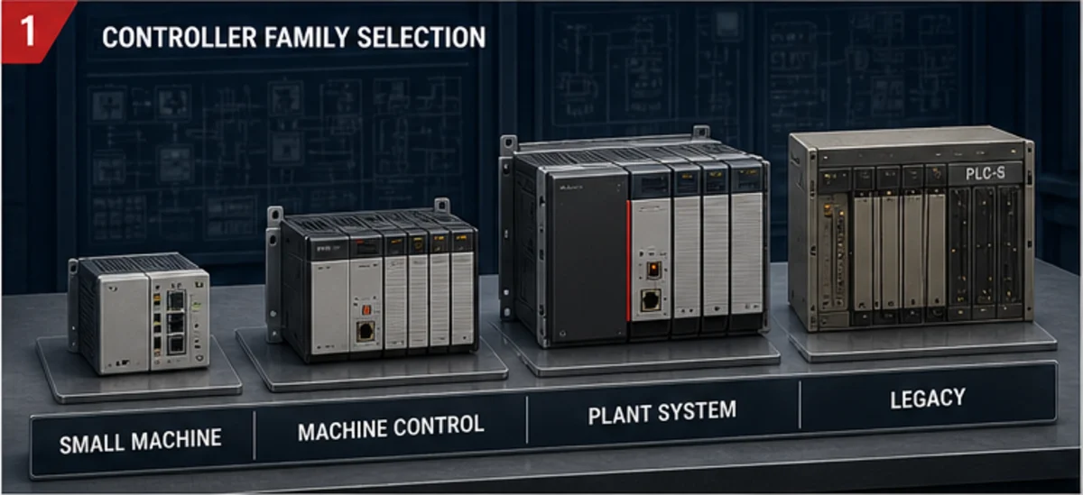
RSLogix 500 is the programming environment associated with supported SLC 500 and MicroLogix controller projects. RSLogix 5000, renamed Studio 5000 Logix Designer beginning with version 21, is the engineering environment for Logix 5000-family controllers such as ControlLogix and CompactLogix. Studio 5000 is not a software upgrade that opens an RSLogix 500 project in place: migration changes controller hardware, I/O, data organization, tasks, communications, and often HMI references.
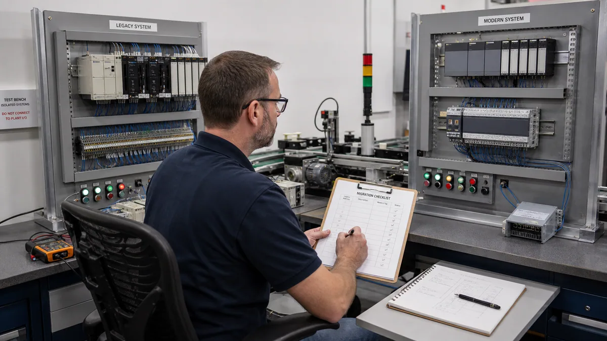
RSLogix 500 vs RSLogix 5000 in one table
| Decision area | RSLogix 500 | Studio 5000 Logix Designer |
|---|---|---|
| Controller family | Supported SLC 500 and MicroLogix controllers | Supported ControlLogix, CompactLogix, and other Logix 5000-family controllers |
| Data model | Address-based data files such as B3, N7, T4, and C5 |
Named controller/program tags, arrays, structures, and module-defined data |
| Program model | Ladder files and subroutines around the legacy scan model | Tasks, programs, routines, and controller/program scopes |
| Languages | Ladder logic in the classic environment | Ladder, Structured Text, Function Block, and SFC where supported by the controller and software edition |
| Reuse | Copy, library, and documented file/address conventions | Add-On Instructions, user-defined data types, produced/consumed tags, and libraries where supported |
| Hardware configuration | SLC/MicroLogix chassis, modules, channels, and legacy networks | Logix module profiles, EtherNet/IP architecture, tasks, motion, safety, and distributed I/O options |
| Lifecycle decision | Maintain when the exact hardware/software remains supportable and risk is accepted | Use for supported Logix projects; version/controller compatibility still needs control |
| Migration | Archive and map every address, I/O point, instruction, message, and dependent client | Rebuild the contract, convert where useful, review exceptions, and validate behavior |
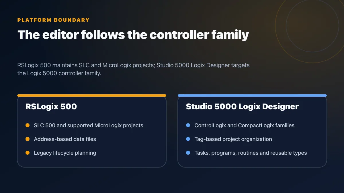
Naming clarification: RSLogix 5000 vs Studio 5000
RSLogix 5000 and Studio 5000 Logix Designer describe the same Logix engineering product lineage before and after the version 21 naming change. People still search for “RSLogix 5000,” but use Studio 5000 Logix Designer when checking current compatibility, licences, release notes, and training.
Do not confuse:
- RSLogix 500 — SLC 500/MicroLogix project environment;
- Studio 5000 Logix Designer — Logix 5000 controller programming;
- Connected Components Workbench — Micro800 controller engineering;
- FactoryTalk software — a broader Rockwell portfolio that can include visualization, data, and other services.
The exact controller catalogue number and firmware major revision determine which software product and version can open, convert, or download the project.
The core programming difference: address files vs tags
An RSLogix 500 project commonly refers to data by file address:
I:1/0      physical/discrete input reference
O:2/3      physical/discrete output reference
B3:0/5     internal Boolean
N7:10      integer
T4:0       timer structure
C5:0       counter structure
A Logix project uses named tags and module-defined structures:
Local:1:I.Data.0
Local:2:O.Data.3
Conveyor.StartPermissive
Batch.RecipeNumber
FillDelay
AcceptedPartCount
Named tags can make intent clearer, but renaming alone does not create a safe migration. Each destination needs a type, scope, owner, range, scale, retentive expectation, HMI mapping, and test.
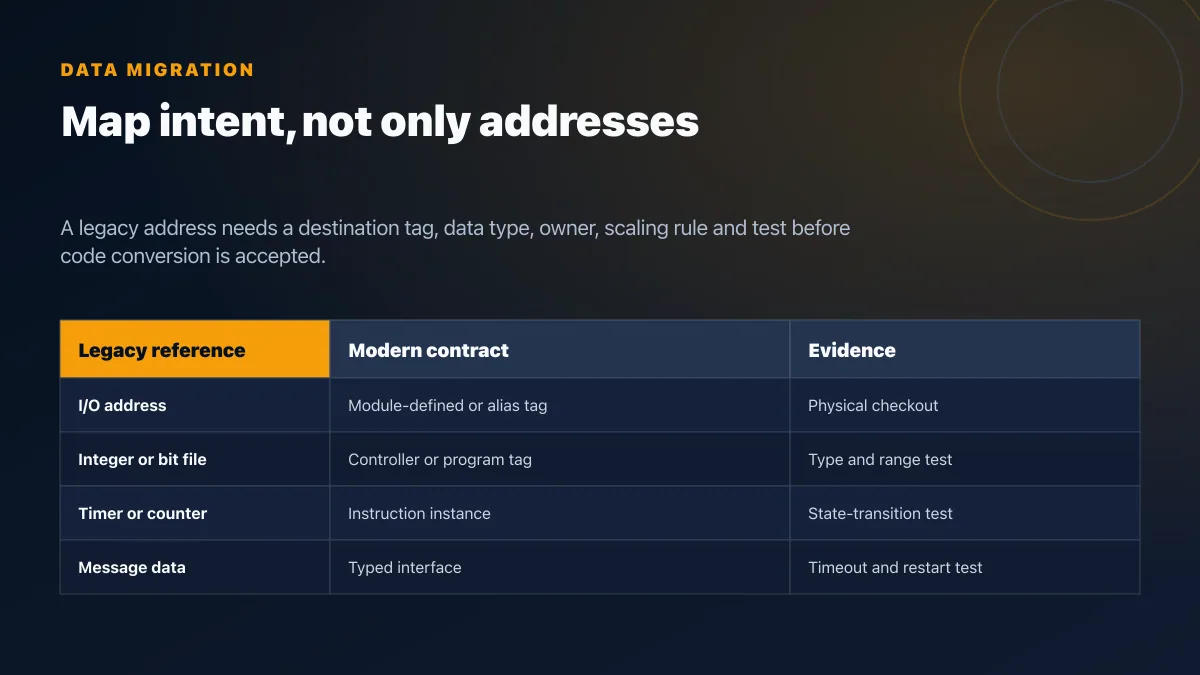
A practical mapping register
| Legacy source | Destination design | Required check |
|---|---|---|
| Physical input/output | Module-defined tag or intentionally documented alias | Chassis, slot, channel, electrical type, filter, fault, and safe-state checkout |
B3 internal bits |
BOOL tags, arrays, or typed state | Retentive/startup state and every external reference |
N7 integers |
INT/DINT or typed structure member | Range, sign, scaling, overflow, HMI, and message expectations |
| Timers/counters | Logix instruction instance | Preset units, accumulator, reset, enable/done state, retentive behavior |
| PID/control data | Supported Logix control instruction and data | Execution interval, tuning, modes, limits, bumpless behavior, and alarms |
| MSG data | Supported Logix communication instruction/interface | Route, data type, timeout, stale data, restart, and ownership |
| Indexed/indirect logic | Array/index logic with explicit bounds | All valid and invalid indices |
| HMI/historian address | New tag path or gateway mapping | Read/write rights, quality, timestamp, and update behavior |
Live mini-lab
Try it: press START, then STOP
A stop-dominant seal-in rung: START latches the motor output through its own contact, and STOP breaks the circuit.
Watch the output lamp: it stays on after START until you press STOP.
Free to start · runs in your browserOpens plcsimulationsoftware.com — same team
Project organization and execution
RSLogix 500 projects typically organize ladder files and data files around the controller's legacy scan and interrupt capabilities. Studio 5000 organizes code into tasks, programs, and routines. Tasks can be continuous, periodic, or event-driven where supported.
That flexibility can change behavior if a migration simply redistributes old code:
- input and output data may update on a different schedule from logic;
- periodic tasks can pre-empt lower-priority work;
- produced/consumed tags and module connections have requested packet intervals;
- timer and state behavior can be affected by task execution and restart;
- an HMI or message may observe tags between different program updates;
- safety and motion have controller-specific scheduling and validation rules.
Create an execution map before conversion: old ladder-file call order, interrupts, input filtering, output updates, messages, critical deadlines, and watchdog behavior. Then define the new task period, priority, program order, I/O connection, and timing evidence.
Hardware and network migration
A software conversion does not select the replacement controller. Freeze:
- current chassis, processor, memory use, modules, specialty I/O, power, and enclosure;
- field voltage/current, isolation, commoning, wiring, terminals, and spare points;
- remote I/O, serial links, DH-485, DH+, DeviceNet, ControlNet, EtherNet/IP, and third-party gateways;
- HMI, historian, SCADA, MES, drive, robot, barcode, scale, printer, and peer-controller dependencies;
- motion, safety, high-speed counter, ASCII, and recipe functions;
- environmental, availability, cybersecurity, support, and lifecycle requirements.
Build a point-by-point I/O conversion schedule. A replacement module with the same point count may still differ in wiring, current, isolation, diagnostic behavior, filter, update, safe state, or terminal system.
Check every product's current lifecycle status in Rockwell's Product Lifecycle Status resource and verify regional stock/support. Do not state that all SLC or MicroLogix products share one discontinuation date.
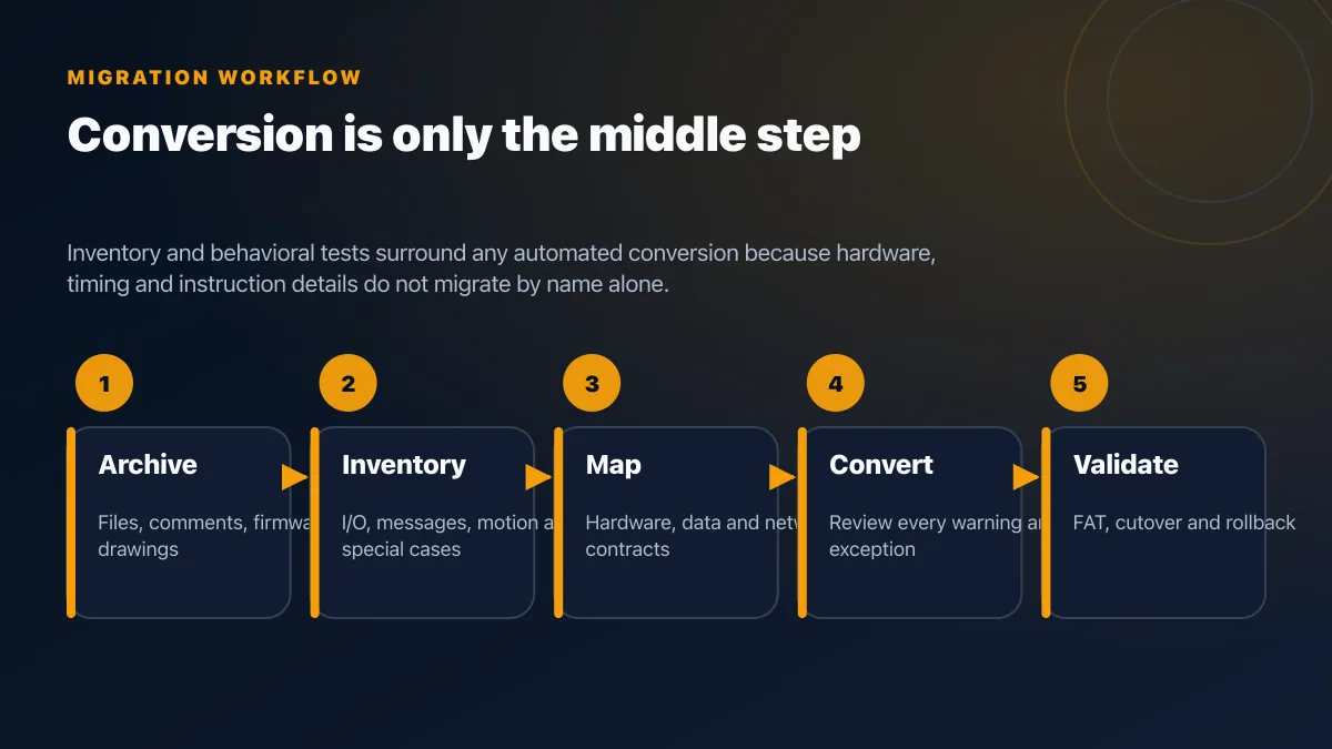
Migration workflow
1. Preserve a restorable baseline
Upload and save the latest controller project with data values where the approved tool supports it. Export reports, symbols, comments, cross references, channel configuration, I/O configuration, message routes, recipes, HMI files, historian tags, drawings, manuals, firmware, software installers, activations, and passwords through the site's controlled process.
Photograph and label the chassis, modules, wiring, networks, switches, and field terminals. Record what cannot be restored from the project file.
2. Inventory risk before choosing hardware
Classify each dependency:
- direct conversion candidate;
- requires manual redesign;
- requires replacement hardware or gateway;
- requires a vendor or safety specialist;
- cannot be tested until an outage;
- has no current spare or support route.
Special attention goes to indirect addressing, sequencers, masked operations, messaging, PID/control, high-speed functions, interrupts, retentive state, first-scan logic, math overflow, and undocumented HMI writes.
3. Freeze mappings and interfaces
Approve the I/O conversion schedule, tag naming/scoping standard, execution plan, network design, HMI/historian mapping, message contracts, alarm list, cybersecurity zones, acceptance tests, and rollback.
4. Convert as an aid, not as proof
Rockwell or third-party migration utilities may translate portions of a project. Tool output must be reviewed against its conversion log and current documentation. “No compile error” does not establish equivalent timing, I/O, communications, data types, state, or fault behavior.
Keep a decision log for every converted warning, manual rewrite, and accepted difference.
5. Validate offline and on a representative bench
Exercise normal sequences, permissives, interlocks, modes, timers, counters, analog scaling, alarms, recipes, communications, restart, and failure recovery. Use simulation for PLC logic fluency and early regression, then use the target controller/I/O for behavior that depends on hardware, firmware, tasks, networks, motion, or safety.
6. Cut over with rollback
Define the outage owner, backups, spare parts, wiring checks, download, I/O checkout, dry cycle, guarded production trial, go/no-go criteria, rollback trigger, stabilization period, and post-cutover archive. Safety functions follow the approved safety lifecycle and validation plan.
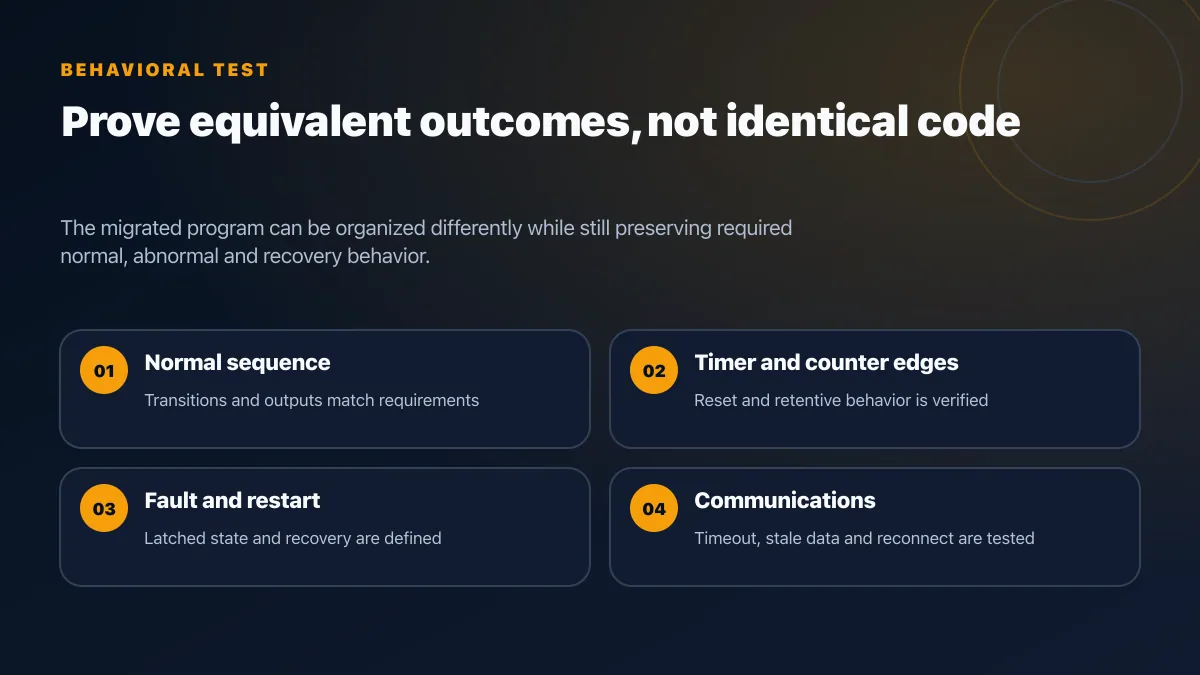
Behavioral equivalence test
The migrated program does not need identical code layout. It needs equivalent required outcomes and explicitly approved improvements.
| Test group | Stimulus | Evidence |
|---|---|---|
| Power-up | Cold start, warm restart, controller mode change | Outputs, retained state, first-scan behavior, alarms |
| Normal sequence | Minimum, nominal, and maximum operating cases | State transitions, outputs, timers, counts, cycle trace |
| Permissive/interlock | Remove each condition in an approved test state | Command inhibition, diagnostics, operator message |
| Timer/counter | Edge, reset, pause, fault, and restart cases | Preset/accumulator and status transitions |
| Analog | Minimum, midpoint, maximum, out-of-range, bad input | Scale, clamp, alarm, quality, fallback |
| Message | Good response, stale data, timeout, destination restart | Status, retry, ownership, recovery, alarm |
| HMI/historian | Read, authorized write, rejected write, bad quality | Tag mapping, rights, feedback, timestamp, audit |
| Hardware fault | Module removal or field fault in an approved lab | Controller diagnostics, output state, recovery |
| Rollback | Invoke the documented rollback | Restore time, configuration integrity, machine state |
Licensing and cost
Do not publish one Studio 5000 or RSLogix 500 price. Rockwell software names, editions, entitlements, subscriptions, support, and regional distributor terms change. Request a dated quote tied to:
- exact controller and firmware families;
- required programming languages and optional features;
- engineering and maintenance seats;
- activation method, virtualization, offline use, and disaster recovery;
- compare, emulation, safety, motion, and network tools;
- support and upgrade rights;
- training;
- legacy software/operating-system requirements during the transition.
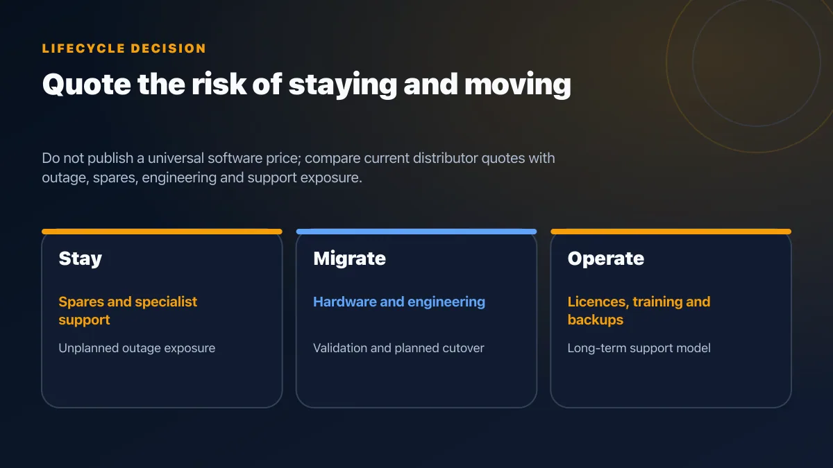
Use a matched lifecycle model:
decision cost = hardware + software + engineering + testing + outage + training + spares + support + expected risk exposure
Quote the cost of staying and moving. A stable legacy machine may justify a planned spare-and-support strategy; a critical controller with no tested restore or spare path may justify migration even when the new controller has no direct feature benefit.
Which platform should you learn?
Learn the platform used by the equipment you must support:
- Learn RSLogix 500 addressing, data files, ladder, online troubleshooting, and archival practice when a site still owns SLC/MicroLogix assets.
- Learn Studio 5000 tags, module-defined data, tasks/programs/routines, online edits, faults, EtherNet/IP, and project/version control for current Logix work.
- Learn electrical drawings, I/O checkout, safety boundaries, networks, sequences, fault diagnosis, and change control regardless of editor.
For a portfolio, build one small sequence both ways. Document the address-to-tag map, execution differences, I/O contract, timer/counter tests, abnormal states, and recovery. Practice the logic in PLC Simulation Software before using a supervised hardware lab. The browser simulator is a learning tool; it does not emulate SLC, MicroLogix, ControlLogix, CompactLogix, EtherNet/IP timing, or vendor safety behavior.
Frequently asked questions
Is RSLogix 5000 the same as Studio 5000?
RSLogix 5000 became Studio 5000 Logix Designer beginning with version 21. Use the current name when checking licences and compatibility.
Can Studio 5000 program an SLC 500 or MicroLogix controller?
No. Use the programming product supported by that exact controller. Studio 5000 Logix Designer targets supported Logix 5000-family controllers.
Can an RSLogix 500 project be converted automatically?
A migration utility can assist with some code and data translation, but hardware, I/O, tasks, instructions, communications, HMI references, and fault behavior require engineering review and testing. Treat the conversion log as a work list.
Is tag-based programming faster than address-based programming?
Naming style does not determine controller performance. Measure task execution, I/O updates, communications, and application response on the selected hardware and project.
Is SLC 500 discontinued?
Lifecycle status is catalogue-number specific and can change. Check Rockwell's current Product Lifecycle Status resource plus regional support and spare availability for the exact processor and modules.
How long does migration take?
Estimate from the inventory, conversion exceptions, panel/I/O work, external clients, required tests, outage, and rollback. A generic project-duration range would not be reliable.
Should I migrate a working machine?
Migrate when the risk-reduction and operating benefit justify the engineering, validation, outage, and new lifecycle. A working controller can still have unacceptable spare, software, backup, security, or recovery risk; another can remain supportable with a documented plan.
Primary sources and review basis
- Rockwell Automation: Studio 5000 design software — current product family and Logix Designer positioning.
- Rockwell Automation: Product Lifecycle Status — catalogue-number lifecycle lookup.
- Rockwell Automation Product Compatibility and Download Center — software, firmware, operating-system, and product compatibility.
- Rockwell Automation Literature Library — controller manuals and migration publications; search by the exact controller and publication number.
Product compatibility, lifecycle, features, licences, and support change by catalogue number, firmware, software release, edition, and region. This guide was technically reviewed on 2026-07-25.
Conclusion
RSLogix 500 remains necessary knowledge where supported SLC and MicroLogix assets are still in service. Studio 5000 Logix Designer is the environment for supported Logix 5000-family controllers. The migration decision is not “old addresses versus modern tags”; it is whether the new hardware, execution model, I/O, networks, clients, safety boundaries, lifecycle, and recovery have been mapped and proven.
Continue with the Studio 5000 programming guide, the PLC ladder logic examples, or the Allen-Bradley controller guide.
Now run it · free to start
Practise RSLogix-style ladder in your browser
Run XIC, XIO, OTE, timers and counters without installing RSLogix or Studio 5000. An independent learning tool — free to start.
Ownership disclosure: PLC Programming IO and PLC Simulation Software are operated by the same publisher.