PLC–HMI Communication: Tags, Handshakes and Troubleshooting
Connect a PLC and HMI through a controlled interface contract: choose the driver, map tags, acknowledge commands, expose data quality, budget traffic and diagnose the first failed boundary.
Review status: Editorially reviewed against current Rockwell Automation, Siemens, Schneider Electric, OPC Foundation, Weintek, Modbus Organization, NIST and OSHA sources; exact protocols, tag models, limits, timing and security controls require installed-product and site verification
Direct answer
Reliable PLC–HMI communication requires more than a reachable IP address or a green connection icon. Choose a communication method that both installed products support, configure compatible endpoints, then define a versioned interface contract for every exchanged item. The contract should identify the tag, meaning, owner, direction, data type, engineering unit, access, valid range, expected update class, maximum acceptable age, quality behavior and test case. The PLC should remain the authority for process state, command validation, interlocks and safe behavior; the HMI should present requests and feedback without pretending that a transmitted click is a completed machine action.
For a consequential operator command, use a retained request plus a sequence or toggle value. The PLC validates the request, accepts or rejects it once, executes through application logic, and returns explicit status such as accepted, busy, done or rejected with a matching sequence. This prevents a short HMI pulse from being missed and helps prevent an old request from repeating after a disconnect. Display values also need quality and freshness. A plausible last-good pressure value must become visibly stale when updates stop.
Commission from the bottom up: power and physical link, network route, HMI driver session, one known read tag, exact data representation, one supervised write, command acknowledgement, normal traffic load, loss and restart recovery, and finally authorized process proof. During a fault, find the first boundary where expected and observed state diverge: HMI object, runtime/driver, network, PLC external interface, PLC logic, output/field process, or feedback. Change one controlled variable at a time and retain evidence.
| If the symptom is… | Prove first | Then inspect | Do not conclude yet |
|---|---|---|---|
| every tag is unavailable | power/link, route and configured endpoint | driver session, controller service, credentials and capacity | that the PLC program is wrong |
| one tag is wrong | raw controller value and exact HMI tag definition | symbol/address, type, scaling, access and revision | that the whole connection is unstable |
| values freeze but look plausible | quality, heartbeat and last-success age | session recovery, server load, polling queue and network loss | that the process really stopped changing |
| button animates but action does not occur | request, sequence, acknowledgement and reject reason | authority, mode, permissives, logic state and field feedback | that the HMI write never arrived |
| response becomes slow on busy screens | measured update age and request rate | visible-screen groups, subscriptions, scan classes and other clients | that faster polling is the cure |
| failure appears after a download | interface revision and published symbols | renamed tags, optimized access, server scope and HMI cache | that hardware failed simultaneously |
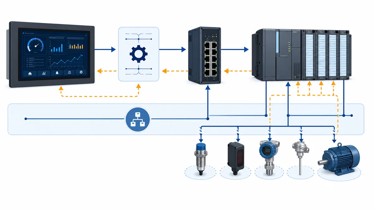
Define the PLC–HMI communication boundary
Treat the interface as a product between two projects
The PLC application and HMI application are often edited, downloaded and versioned separately. A tag that exists in one is not automatically a stable interface for the other. Treat their shared boundary like a small product with an owner, a release number, compatibility rules and acceptance evidence. This makes a screen change less likely to break controller behavior and a controller refactor less likely to silently invalidate an HMI.
A direct symbolic connection can remove manual numeric addresses, but it does not remove the contract. The controller symbol, external-access setting, data type and structure still need stable meaning. Siemens describes external tags as HMI-side images of defined PLC memory locations for reading and writing. Rockwell FactoryTalk View separates communication setup from HMI tags and controller data. Schneider's symbol configuration publishes selected variables for HMI exchange. The mechanics differ, but the integration need is the same: deliberately expose an agreed interface rather than browse every internal implementation tag.
Assign ownership before configuring a driver
For each value, write down who owns the authoritative state and who may request a change. Measurements, machine state, active mode, interlocks and executed-command state normally originate in PLC logic. The HMI may own presentation state and may originate operator requests, but the PLC must validate those requests against current authority, mode, range and permissives. Hiding a button or restricting a screen improves usability and access control; it is not final process enforcement.
| Interface class | Authoritative owner | HMI action | PLC action | Required loss behavior |
|---|---|---|---|---|
| measurement | PLC/process acquisition | read and render with unit, quality and age | publish validated engineering or raw state | mark stale or unavailable |
| status/mode | PLC application state | display actual state, not inferred button state | publish enumerated state and transitions | show unknown when state is no longer fresh |
| setpoint request | operator through HMI | submit candidate and show pending/result | validate, clamp or reject by defined policy; publish active value | preserve known actual state and make request result uncertain |
| command request | operator through HMI | create retained sequenced request | authorize, acknowledge once and execute via state logic | do not repeat automatically after reconnect |
| alarm/event acknowledgement | user/HMI event service | identify user and acknowledgement request | follow alarm-system ownership and audit policy | queue or reject explicitly; never imply success |
| recipe/parameter block | controlled engineering/operator workflow | transfer versioned candidate block | validate completeness, range and revision before commit | reject partial or mixed-revision data |
Keep safety functions outside ordinary HMI communication
An ordinary HMI connection is not a safety channel merely because it runs on an industrial protocol. Emergency stops, guards and safety functions require the site's approved safety architecture, validated devices and lifecycle. An HMI may display safety status, but its ordinary button, authentication layer or network session must not become the sole safety measure. Lockout/tagout, electrical safe-work rules and local authorization still apply during testing.
Choose the connection architecture deliberately
Compare native symbolic, OPC UA, Modbus and gateway patterns
There is no universal “best PLC–HMI protocol.” Prefer a supported native or symbolic driver when the controller and HMI combination is approved, version compatibility is controlled, tag browsing reduces mapping risk, and required diagnostics are available. Consider OPC UA when its information model, subscriptions, security modes, certificates and status codes match the products and governance. Use Modbus when a simple interoperable register/coil contract is appropriate and its address/type limitations are explicitly managed. A serial or protocol gateway is reasonable when it is required, but it adds another queue, identity map and diagnostic boundary.
| Pattern | Strong fit | Contract work that remains | Main diagnostic risk |
|---|---|---|---|
| native symbolic driver | supported PLC/HMI family with managed versions and browseable controller tags | symbol scope, external access, type compatibility, structure changes and revision | project download or firmware changes invalidate a previously browsed symbol |
| OPC UA | cross-vendor client/server exchange needing typed nodes, security and explicit status | namespace/node identity, certificates, user/token policy, subscription settings, status and timestamp behavior | session can exist while individual nodes are Bad, Uncertain or unauthorized |
| Modbus TCP | simple cross-vendor cyclic exchange over Ethernet | client/server roles, table, zero-based offset, function, width, word order, scaling and access | correct socket with wrong register convention or data representation |
| serial Modbus RTU | modest serial device segment with controlled timing and wiring | node IDs, baud/parity/stop, termination/bias/reference, timing and register contract | wiring, framing, collision or gateway queue appears as an application timeout |
| protocol gateway | legacy or mixed networks where direct compatible drivers are unavailable | both endpoint contracts plus translation, routing, buffering and failure policy | healthy upstream connection hides failed downstream device or stale cache |
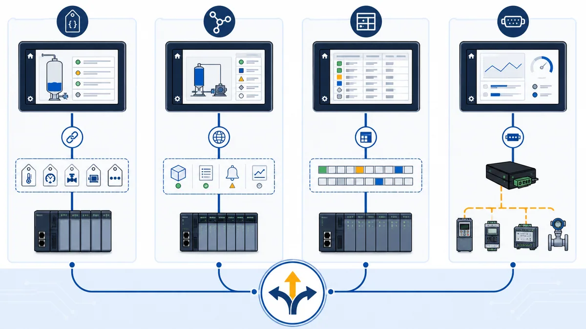
Verify support from both product manuals
Record the exact PLC model, firmware, HMI runtime/panel version, driver version, protocol role and licensed feature. A vendor family name is not sufficient. Rockwell's current FactoryTalk View documentation, for example, has different communication setup paths for FactoryTalk Linx and OPC data servers. Siemens WinCC communication documentation lists supported channels and driver-specific properties. Weintek's EasyBuilder Pro manual documents device settings and communication parameters for its runtime. Use the manuals for the exact installed versions because menus, drivers, certificates, limits and tag types change.
Define endpoints and identity explicitly
For Ethernet, record device IP address, subnet, route/VLAN, TCP/UDP service as applicable, controller slot or path, server name, certificate identity and any gateway mapping. For serial, record physical interface, topology, node ID, baud rate, parity, data/stop bits, termination, bias and reference. Also record how duplicate identity is prevented. A ping proves an IP response, not that the configured controller service, path, symbol or user is correct.
Build a versioned tag contract
Give every exchanged item a reproducible definition
The minimum useful contract is more than “HMI tag name → PLC tag name.” It needs enough information for another engineer to reconstruct the connection and predict failure behavior. Store it with the PLC and HMI release records, export it to a reviewable format, and run checks for duplicate names, duplicate addresses, overlapping widths, unsupported types, multiple writers, missing units and missing test IDs.
| Contract field | Example form | Release question |
|---|---|---|
| stable interface ID | PKG01_SPEED_PV |
does this name survive screen layout and internal code refactoring? |
| process meaning | actual package conveyor speed | could a different engineer distinguish actual, requested and commanded values? |
| source/destination | PLC published status → HMI display | is authoritative ownership unambiguous? |
| symbolic node/address | controller symbol, OPC UA NodeId or Modbus location | can the exact installed driver reproduce it? |
| type/width | Boolean, signed 16-bit, 32-bit float, enum, structure | do both endpoints agree on representation and range? |
| unit/scaling | rpm; engineering value already scaled | can scaling be applied exactly once and tested at several points? |
| access | read-only, request-write, engineering-only | are broad writable internal tags excluded? |
| validity | minimum/maximum, state constraint, invalid sentinel policy | what must the PLC reject or the HMI mark invalid? |
| quality/freshness | quality source, update class, maximum age, heartbeat group | when must a plausible value stop looking live? |
| command semantics | request, sequence, accepted, busy, done, rejected/reason | can every outcome and reconnect be reconciled? |
| version/test | interface revision and acceptance case | is evidence tied to the exact PLC/HMI pair? |
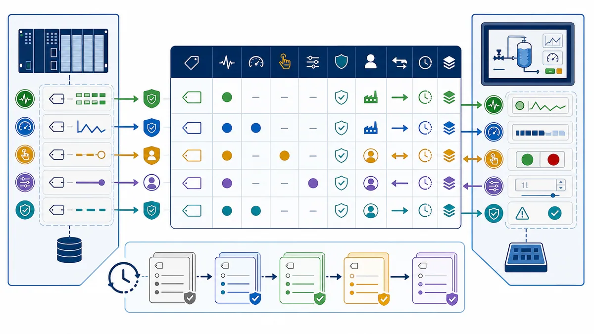
Separate public interface tags from internal implementation tags
Create a deliberate external structure or namespace where the controller platform allows it. Publish stable status, measurements, accepted settings, request fields, acknowledgement fields, quality and interface version. Keep internal step bits, temporary calculations, intermediate permissives and hardware-specific members private unless the HMI genuinely needs them. This reduces accidental coupling: PLC logic can be refactored behind the boundary without forcing every screen object to change.
Schneider documents selecting variables for symbol configuration and assigning HMI access rights. Rockwell documents both direct-reference and HMI-tag approaches, depending on application type and data source. These are product-specific mechanisms, not universal syntax. The design principle is portable: expose the narrowest stable interface and verify it after controller or HMI version changes.
Prove representation with diagnostic values
Use distinctive safe test values instead of relying on a normal process value that could look correct under multiple wrong interpretations. Prove Boolean state, signed negative value, upper-range integer, fractional floating value, enum/status value, packed bits and text independently where used. For mapped protocols, inspect raw words or bytes. For symbolic or typed connections, confirm the actual type exposed by the server and accepted by the client rather than trusting a similarly named HMI data type.
| Data defect | Typical symptom | Controlled proof | Durable correction |
|---|---|---|---|
| signed/unsigned mismatch | negative PLC value becomes a large positive HMI value | publish safe -1 and boundary values |
make type identical or define explicit conversion |
| 32-bit word order mismatch | float is enormous, tiny or unstable | publish known bit pattern and several exact values | document and configure word order at the mapped endpoint |
| scaling twice | displayed value is ten or one hundred times expected | compare raw, PLC engineering and HMI displayed values | assign scaling to exactly one controlled layer |
| enum mismatch | wrong mode label appears | step through every defined and reserved state | version the enum and display unknown for undefined values |
| packed-bit mismatch | adjacent status changes the wrong indicator | toggle one safe bit at a time | document bit position and reserved behavior |
| structure revision mismatch | several members fail after download | compare server type revision and HMI browse/cache | coordinate compatible releases or use a stable flat boundary |
Live mini-lab
Try it: press START, then STOP
A stop-dominant seal-in rung: START latches the motor output through its own contact, and STOP breaks the circuit.
Watch the output lamp: it stays on after START until you press STOP.
Free to start · runs in your browserOpens plcsimulationsoftware.com — same team
Design operator commands as acknowledged transactions
Replace momentary pulses with stateful requests
A momentary HMI button can write true and then false between PLC observations, lose the release write, or reconnect with ambiguous state. For commands where duplicated, missed or uncertain execution matters, use a retained request and unique sequence/toggle. The PLC sees a new sequence, captures the request, validates it, records an acknowledgement result and exposes execution state. The HMI leaves the request pending until it sees the matching acknowledgement or a defined timeout; timeout means uncertain, not automatically failed.
This is application logic, not a universal protocol feature. Exact fields depend on risk and process. A harmless screen-navigation command does not need a machine transaction. Starting motion, changing a recipe, resetting a consequential fault or committing parameters deserves explicit semantics.
| Field | Owner | Example state | Purpose |
|---|---|---|---|
| request code | HMI/operator request | start, stop, reset, commit | identifies requested action without driving output directly |
| request sequence | HMI | increment or toggle for each deliberate submission | distinguishes new request from retained old data |
| requester/session identity | HMI/authentication context | approved role/session reference | supports authorization and audit where required |
| acknowledged sequence | PLC | last processed sequence | lets HMI reconcile exactly which request was considered |
| acceptance state | PLC | pending, accepted, rejected | separates communication receipt from validation |
| execution state | PLC | idle, busy, done, failed | reports application progress and terminal outcome |
| reason/result | PLC | mode, permissive, range, authority, process fault | gives the operator a bounded next action |
| actual process state | PLC/field feedback | running, stopped, position/flow achieved | proves result independently from command acknowledgement |
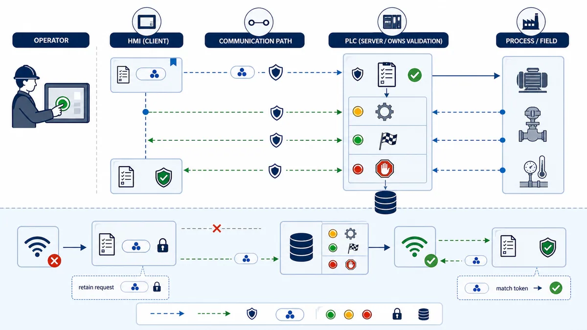
Make duplicate and reconnect policy explicit
The PLC should process a given sequence once. If the connection drops after the request arrives but before the acknowledgement returns, the HMI must not invent a second request. On reconnect, it reads the PLC's acknowledged sequence and execution state, then reconciles the pending transaction. Define what happens when the sequence wraps, the HMI project is restarted, two stations issue requests, or controller memory is non-retentive after power loss.
Show rejected and uncertain outcomes honestly
Do not animate a button as “running” merely because its write completed. Show pending while awaiting acknowledgement, rejected with a useful bounded reason when the PLC declines it, busy while application logic executes, done only after the defined execution condition, and uncertain when communication prevents reconciliation. Operators need the actual mode, permissive or process feedback required for the next safe action.
Carry quality, freshness, heartbeat and time
Inspect per-item quality where the protocol provides it
OPC UA DataValue includes a StatusCode, and the specification defines Good, Uncertain and Bad severity. A client should inspect and map that status rather than treating any numeric payload as current. Other drivers may expose per-tag quality, group quality, communication status, last-error codes or only a session state. Document what the installed driver actually supplies; a connected session can coexist with unauthorized, unknown, stale or bad individual items.
Add application freshness independent of the connection lamp
Use a PLC-generated heartbeat counter or changing token that the HMI reads with the related tag group. Record the last successful value change or successful update time on the HMI side, and compare it with the group's maximum acceptable age. A Boolean that merely stays true is weak evidence because a cached true value looks healthy after updates stop. A counter or monotonic pattern makes frozen data visible.
| State | Communication evidence | HMI presentation | Operator interpretation |
|---|---|---|---|
| live/good | expected quality and age within threshold | normal value, unit and status | current within the defined update contract |
| delayed | updates continue but age approaches threshold | amber latency/age cue without hiding value | value may lag; avoid time-critical inference |
| stale | heartbeat/value group no longer updates by maximum age | visibly stale style, age and unavailable control as designed | last known value, not current process truth |
| bad | driver/protocol reports bad item or conversion | bad-quality symbol and no false precision | value cannot be trusted for operation |
| uncertain | protocol or application reports uncertain, or reconnect is unresolved | explicit uncertain state | confirm at another approved evidence source |
| recovering | session returns but contract has not yet passed resynchronization | recovery indicator; commands reconciled before enablement | wait for current state and pending transactions to settle |
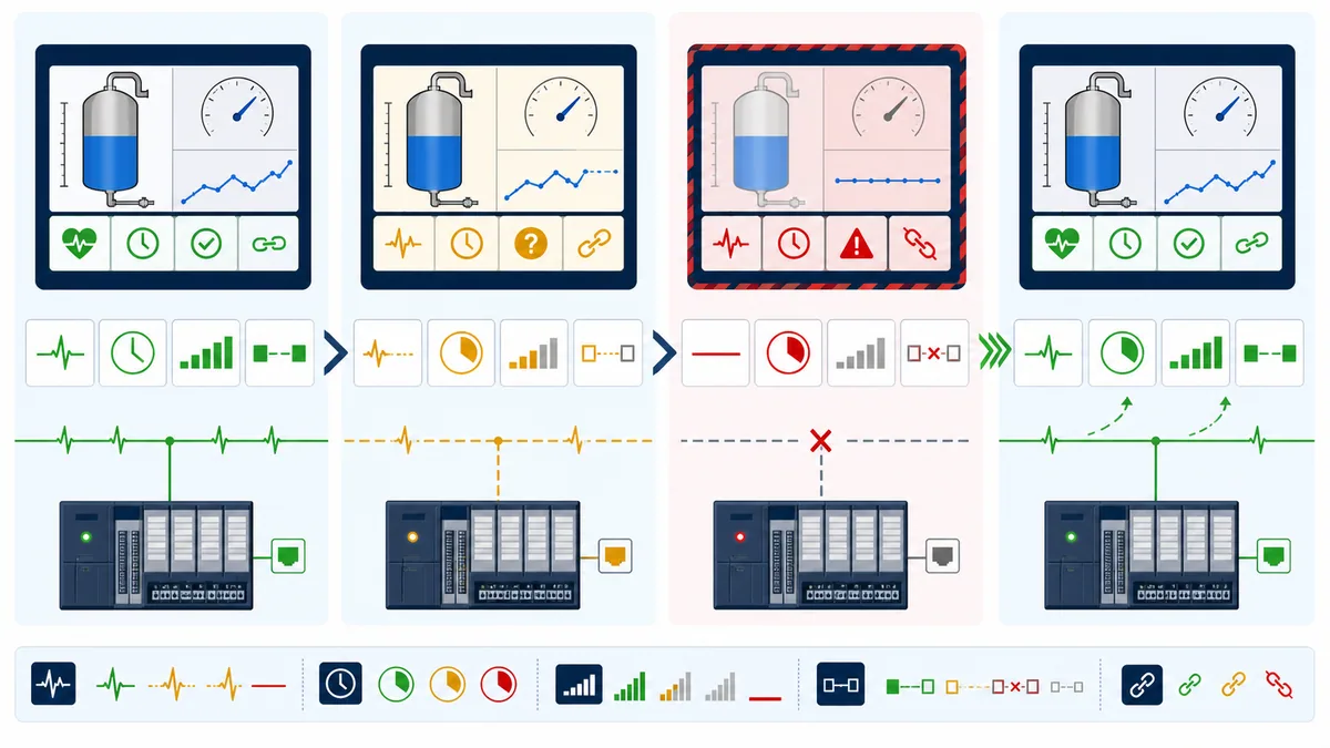
Use timestamps only with a defined clock model
If the PLC supplies source timestamps, define which clock produced them, its synchronization source, timezone/UTC convention, resolution and invalid-time behavior after restart. If the HMI applies receipt time, label that distinction in design records. Clock error can make old data appear new or reorder events, so a timestamp is not automatically stronger than a local age timer tied to successful updates.
Budget update rates and communication load
Classify tags by operational need
Do not assign every tag the fastest selectable scan. Create update classes based on the time in which an operator decision must see a change. A running-state transition may need a faster class than maintenance hours, a configuration page or a historical summary. Use screen visibility or subscription behavior where the runtime supports it, and ensure background alarm or event acquisition follows its own requirements rather than disappearing with a closed display.
Schneider notes that HMI data-exchange refresh depends on the number of variables and controller task performance. That is a useful product-specific warning, not a universal formula. Driver batching, subscription behavior, network latency, controller load, concurrent clients, gateway queues and HMI rendering all contribute. Measure the installed system under normal and worst credible screen/activity combinations.
| Update class | Example content | Starting design question | Acceptance evidence |
|---|---|---|---|
| fast | immediate operating state, active command feedback | how soon must an operator see the change to act correctly? | observed source-to-display age under peak credible load |
| normal | process measurements and standard status | what latency supports routine control-room decisions? | percentile update age and no starvation during navigation |
| slow | maintenance counters, static configuration, diagnostic detail | can seconds of delay change a safe decision? | stable update without consuming priority capacity |
| on-demand | recipe detail, rarely opened service data | can the data be requested when the page opens? | bounded page load and clean cancellation on navigation |
| event/alarm | alarms, acknowledgements and event records | does runtime use polling, subscription or a separate alarm service? | sequence, timestamp, loss/recovery and audit tests |
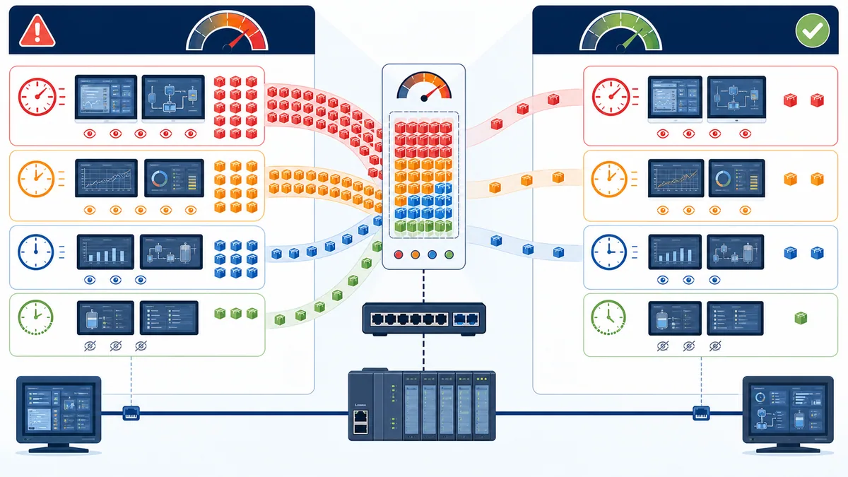
Measure end-to-end age instead of only ping latency
Ping round-trip time says little about tag scheduling. Instrument a controlled PLC value that changes with a known sequence/timestamp, observe when the HMI receives or renders it, and measure a distribution over time. Capture median and high-percentile age, timeout/retry counts, driver queue depth if available, controller task time, CPU/resource load and the effect of opening the heaviest display. Include other real clients such as SCADA, historians, engineering tools and gateways.
Fix load by reducing unnecessary work
Before increasing timeouts, group compatible tags, remove unused items, use native subscriptions or block reads correctly, separate fast/slow classes, reduce off-screen polling, stop retry storms and eliminate duplicate clients. A larger timeout may reduce visible alarms while leaving unacceptable age. A faster scan may make congestion and controller load worse. Change one factor, repeat the same load case and compare evidence.
Configure a PLC and HMI step by step
Freeze identity, versions and recovery access
Back up both projects and record device models, firmware/runtime, driver version, interface revision, network/serial schedule, security/certificate state and authorized recovery method. Confirm a safe rollback and who can approve downloads. Do not begin by changing both applications and the network at once.
Publish the smallest testable PLC interface
Create interface-version and heartbeat items, one read-only Boolean, one read-only numeric value, one safely writable request field with PLC validation, acknowledgement fields, and quality/reject reason as appropriate. Give each a controlled initial and restart state. Enable only the required external access, server service or published symbol set.
Configure one HMI connection and one known tag
Select the exact driver or OPC data server, define endpoint/path/security, then connect one diagnostic tag. Prove the raw value in the runtime's diagnostic or tag monitor before binding a complex screen. If the connection fails, capture the driver's actual error and server/controller log rather than changing unrelated tag definitions.
Expand from types to groups to commands
Add one representative of every data shape, then status groups, measurement groups and slow/on-demand data. Add writes last, beginning with a harmless test request in an authorized environment. Implement the request/acknowledgement state and rejection reason before connecting an operator button to consequential application logic.
Bind objects to actual and requested state separately
Display the PLC's actual state, not the state of the last HMI click. For a motor, show requested action, accepted/busy/rejected transaction state, actual application running state, starter/drive feedback and process proof as separate concepts. Disable or qualify controls when quality, authority or freshness is insufficient, while ensuring the PLC still enforces every rule independently.
Commission in layers and preserve evidence
Run a repeatable commissioning ladder
Each stage should have a known input, expected output, captured observation, pass/fail result and restoration step. When a stage fails, stop and diagnose that boundary rather than compensating in a higher layer. A green screen at the end is not a test record.
| Stage | Controlled action | Expected evidence | Stop condition |
|---|---|---|---|
| 1 | verify approved power/isolation state and physical link | correct device state and link indicators/physical test | unexpected power, wiring or safety state |
| 2 | prove route or serial framing to intended endpoint | correct identity and bounded connection result | duplicate/wrong identity or unstable physical layer |
| 3 | open driver/server session | authenticated/authorized session and useful diagnostics | repeated refusal, certificate, path or capacity error |
| 4 | read one known changing tag | correct value, quality and freshness | cached, wrong or unchanging evidence |
| 5 | test each data type and scale | raw and engineering values match contract | mismatch in sign, width, order, enum or scale |
| 6 | issue one supervised safe request | matching acknowledgement and expected reject/accept path | uncontrolled write or ambiguous outcome |
| 7 | exercise normal and peak credible HMI load | update ages and resources within acceptance limits | starvation, retry storm or controller impact |
| 8 | disconnect, restart and reconnect | stale display, no duplicate command, controlled resynchronization | plausible stale data or repeated transaction |
| 9 | prove authorized process outcomes | command, logic, field action and feedback match requirement | any unreviewed safety/process deviation |
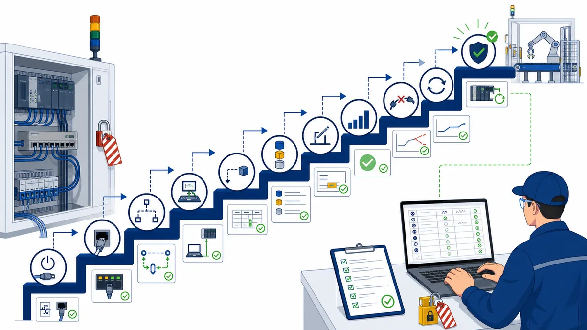
Test loss and restoration as designed states
Remove or block the connection only through an approved safe test method. Verify when every tag group becomes stale, how controls respond, whether alarms/events retain their required semantics, what happens to pending commands, and how the runtime reconnects. Restart the HMI and PLC separately. Confirm sequence reconciliation, clock validity, interface version, retained/non-retained state and current process truth before enabling writes again.
Record evidence that another person can replay
Keep the as-tested project revisions, contract export, network/serial settings, screenshots or logs, request/ack traces, measured update-age results, injected-fault steps, results, deviations and restoration. Redact secrets from broadly shared records. The evidence should answer which version was tested, which environment, who approved the test, what passed, what did not, and what remains a product or site limitation.
Troubleshoot the first failed boundary
Build one shared timeline before changing configuration
Capture operator action time, HMI object state, runtime/tag quality, driver error, network/session event, PLC interface tag, PLC application state, physical output/actuator state and process feedback. Align timestamps cautiously if device clocks differ. The first point that diverges from the expected chain is a better starting hypothesis than the most visible red icon.
Use symptom-specific probes
| Symptom | HMI/runtime probe | PLC/server probe | Network/process probe | Likely boundary after proof |
|---|---|---|---|---|
| all tags bad | connection status, endpoint, driver error, credentials | service enabled, capacity, logs, controller mode | link, route, port/serial frames | identity, driver, route or service |
| only one group bad | group quality, subscription/poll settings | published scope and structure revision | request/response for affected group | contract or access configuration |
| one number wrong | raw HMI tag and type | source value and exposed type | raw words where applicable | type, scale, word/byte order or address |
| values intermittently stale | last success, retries, queue and active display | comm resource/task load and concurrent clients | loss, errors, gateway queue | load, physical/network quality or capacity |
| write reports success but no action | request and sequence values | acknowledgement, reject reason, logic state | output/drive/field feedback | authority, validation, logic or process |
| duplicate action after reconnect | pending transaction and saved sequence | last acknowledged sequence and retained state | connection event timing | handshake/reconciliation design |
| update slows after project growth | item count, class, hidden screens, retries | controller/server performance | traffic rate and other clients | polling/subscription budget |
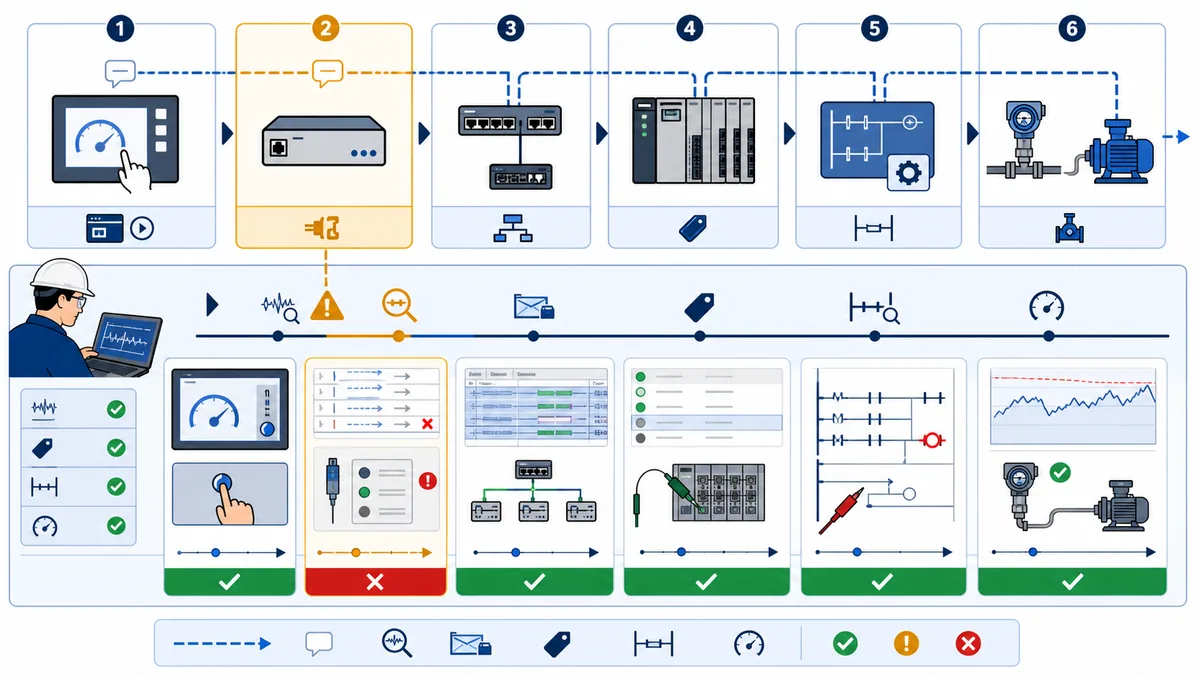
Change one variable and retest the same case
Do not simultaneously change the PLC path, HMI driver, switch port, tag address and timeout. Preserve the failing capture, state one hypothesis, choose the smallest reversible test, repeat the same condition and compare. Revert unsuccessful changes. Once corrected, repeat normal, loss, restart and load tests so the local fix does not create a broader regression.
For deeper protocol-specific work, use the Modbus PLC–HMI communication guide, Modbus register addressing guide or PLC communication troubleshooting guide. For screen design and alarm behavior, use the HMI programming tutorial and HMI alarms, events and trends guide.
Secure writes and remote access in layers
Minimize exposed services and write scope
NIST SP 800-82 Rev. 3 recommends OT security that accounts for performance, reliability and safety requirements. Apply the site's architecture: inventory the endpoints and flows, segment as approved, allow only required services, manage accounts and certificates, protect engineering access, log meaningful events, back up configurations and test recovery. Do not expose a PLC or HMI service directly to the public internet because remote viewing is convenient.
At the application boundary, publish only required external tags. Make status read-only. Route operator changes through validated requests. Restrict engineering parameters by role and operating state, but keep PLC-side validation because an HMI role or hidden object can be misconfigured or bypassed. Store secrets in the product's supported credential mechanism rather than in screenshots, page text or shared spreadsheets.
Separate human authorization from process permission
A logged-in user may have permission to request a mode or setpoint, while the process is currently unable to accept it. Show both decisions. The HMI enforces user workflow and records identity where supported; the PLC evaluates current equipment state, range, interlocks and arbitration. Neither decision alone proves that the field action completed.
Plan degraded operation and recovery
Define what the PLC does when HMI communication is lost, what operators can do through approved local controls, which values the HMI shows after recovery, and how outstanding commands are reconciled. Avoid a generic rule such as “all outputs turn off on HMI loss”: the correct degraded state is process- and hazard-specific and must be engineered in the control and safety design.
Worked conveyor interface example
Define the contract before drawing the screen
Consider a conveyor with a drive, photoeye and downstream permissive. The HMI needs actual run state, drive ready/fault, photoeye, speed feedback, active speed setpoint, mode, permissive summary, communication heartbeat and interface version. It can request start, stop, reset and a new speed setpoint. It does not write the motor output, drive command word or internal step bits directly.
| Interface item | Direction/owner | Update class | Validation and display rule |
|---|---|---|---|
| actual run state | PLC → HMI | fast | derives from application/field feedback; unknown when stale |
| drive ready/fault | PLC → HMI | fast | display distinct ready, not-ready and fault states |
| product photoeye | PLC → HMI | normal | diagnostic state with age; not a safety indication |
| actual speed | PLC → HMI | normal | unit and valid range; bad/stale visibly marked |
| active setpoint | PLC → HMI | normal | value currently accepted by application |
| setpoint request | HMI → PLC | transaction | PLC validates mode, authority, range and rate of change |
| command/sequence | HMI → PLC | transaction | retained until matching acknowledgement |
| ack/result/reason | PLC → HMI | fast | accepted/busy/done/rejected plus matching sequence |
| heartbeat/version | PLC → HMI | normal | detects frozen group and incompatible release |
The start transaction succeeds only when the PLC accepts the new sequence, required mode and permissives are true, application logic enters the start state, the drive command is issued, and actual feedback arrives within the defined time. “Done” should reflect the requirement—for example verified running feedback—not just the setting of an internal command bit. A missing downstream permissive returns a bounded rejection or waits according to the specified state model; the screen explains the actual blocker.
Prove normal, rejected, uncertain and recovered cases
Test a valid start, duplicate start sequence, start without authority, start with missing permissive, drive-not-ready, feedback timeout, disconnect before PLC receipt, disconnect after receipt but before acknowledgement, HMI restart with a pending request, PLC restart, restored connection and peak display load. For each, predict the HMI state, PLC state, physical behavior and recovery. The example is complete only when failure paths are as explicit as the happy path.
Diagnostic answer map for search and AI-assisted integration
Connection and configuration queries
- How do I connect an HMI to a PLC? Verify an exact compatible driver/protocol on both installed products, configure endpoint identity, publish a small controlled PLC interface, prove one known tag, then expand by type and function.
- Which protocol should a PLC and HMI use? Choose from supported native symbolic, OPC UA, Modbus or an approved gateway based on compatibility, diagnostics, security, data model, load and lifecycle—not a universal ranking.
- What tags should an HMI read from a PLC? Stable measurements, actual state, modes, interlocks summarized for operation, alarms/events as designed, quality/freshness and interface version; avoid binding screens to internal temporary logic.
- Can an HMI write directly to PLC outputs? Ordinary design should send validated requests to PLC application logic, not write hardware outputs or bypass interlocks.
Handshake and stale-data queries
- Why does an HMI button work intermittently? A short pulse may be missed or its release may be lost; inspect the actual request and use a retained sequenced request with matching acknowledgement for consequential commands.
- How can an HMI prevent duplicate commands after reconnect? Reconcile the pending request sequence with the PLC's last acknowledged sequence and execution state before issuing anything new.
- How do I know an HMI value is live? Combine item/group quality with a changing PLC heartbeat or update sequence and a maximum acceptable age; do not trust the last numeric value or connection lamp alone.
- What does Bad or Uncertain OPC UA quality mean? OPC UA StatusCode severity distinguishes data quality; map the exact code and product behavior, and never render a numeric payload as good without inspecting its status.
Performance and troubleshooting queries
- How fast should HMI tags update? There is no universal rate. Classify by operator decision need, then measure end-to-end age and resource impact under representative peak load.
- Why are only some HMI tags not updating? Compare the affected tag/group contract, publication/access scope, type and interface revision after proving the common connection is healthy.
- Why is the HMI connected but the PLC does not respond to a button? Connection proves transport only. Trace request, sequence, PLC acknowledgement/reject reason, application mode/permissives, output/drive state and process feedback.
- What should I capture for PLC–HMI troubleshooting? Exact revisions, endpoint/driver status, tag quality and age, raw value, request/ack sequence, PLC interface and logic state, network/session evidence, field output and feedback on one timeline.
These concise answers are extraction aids, not substitutes for the installed manuals, risk assessment, site procedure or captured evidence. Product capabilities and limits vary by version.
Frequently asked questions
What is PLC–HMI communication?
PLC–HMI communication is the controlled exchange of process measurements, states, alarms, settings and operator requests between controller application logic and a human-machine interface. It includes the physical/network path and protocol, but reliable integration also requires tag meaning, ownership, quality, freshness, command semantics, security and test evidence.
How do I connect an HMI to a PLC?
Confirm exact product and version compatibility, select a supported native driver, OPC UA, Modbus or approved gateway, configure endpoint identity and security, publish a small PLC interface, and prove one known read tag. Then test every data type, add grouped tags, add supervised writes and acknowledged commands, and validate loss, restart and load behavior before process commissioning.
Which PLC–HMI protocol is best?
No protocol is best for every installation. A native symbolic driver can simplify supported same-family integrations; OPC UA can provide typed nodes, security and explicit status; Modbus provides a simple widely implemented data model but requires careful addressing and representation; gateways solve compatibility at the cost of another boundary. Decide from installed support, lifecycle, diagnostics, load and security requirements.
Why is my HMI connected but tags are not updating?
A session can be connected while individual items are unpublished, unauthorized, misaddressed, type-incompatible, stale or outside a subscription/poll group. Prove one known changing source value, inspect tag quality and age, compare exact symbol/address and type, verify external access and revision, and check driver/server diagnostics before altering timeouts.
Why does an HMI show the wrong PLC value?
Compare the controller source, raw transferred value and rendered engineering value. Common causes are a one-address shift, wrong symbolic member, signed/unsigned mismatch, wrong width or word order, enum revision, bit position, scaling applied twice, or stale cached data. Use distinctive safe test values and change one variable at a time.
Should an HMI button write directly to a PLC bit?
A simple non-consequential UI request may use a direct Boolean where behavior is fully defined. For commands that must not be missed, duplicated or left uncertain, use a retained request plus sequence/toggle and PLC acknowledgement. The PLC must still validate authority, mode, range and interlocks and report actual process outcome separately.
How do I detect stale HMI data?
Use available item or group quality plus a PLC-generated heartbeat counter or update token and a maximum acceptable age. When the limit is exceeded, visibly mark values stale and qualify controls. A steady true heartbeat bit or green connection lamp is insufficient because a cached value can remain plausible after updates stop.
How often should an HMI poll a PLC?
There is no universal best interval. Classify tags as fast, normal, slow, on-demand or event/alarm based on operational need, account for driver batching/subscriptions and all concurrent clients, then measure actual source-to-display age, retries, controller load and recovery under representative peak conditions.
How do I troubleshoot intermittent PLC–HMI communication?
Build a shared timeline and locate the first failed boundary: object/tag, runtime driver, network, PLC external interface, application logic, output/field process or feedback. Capture errors, quality, age, request/ack sequence, resource load and traffic evidence. Test one reversible hypothesis, retest the same condition, then run loss, restart and load regression cases.
Can I test PLC–HMI communication in a simulator?
Yes, a simulator can help prove tag contracts, data types, command acknowledgements, stale-state displays, loss/reconnect logic and diagnostic reasoning. It cannot prove installed driver compatibility, field wiring, controller/network capacity, real process dynamics, cybersecurity controls or safety functions. Repeat acceptance tests on approved target hardware and procedures.
Sources, review scope, and limitations
This guide was last reviewed on 29 August 2026. It is a protocol-neutral engineering and troubleshooting method, not a replacement for the manuals, validated application design, cybersecurity program, safety lifecycle or site work procedure. Product menus, supported protocols, symbol behavior, licensing, connection limits, certificates and performance change by model, firmware, runtime and region. The cited product documentation supports specific examples only; it does not establish universal compatibility.
Primary sources reviewed:
- Rockwell Automation: FactoryTalk View 16—Set up communications — current FactoryTalk View SE communication setup and data-server boundary.
- Rockwell Automation: FactoryTalk View ME User's Guide, October 2025 — current ME project, communication and runtime reference; exact edition applies.
- Rockwell Automation: FactoryTalk View—Set up OPC communications — product-specific OPC server/client configuration context.
- Rockwell Automation: Configure FactoryTalk Linx for FactoryTalk View ME — communication path and runtime configuration boundaries.
- Rockwell Automation: FactoryTalk View tags editor — HMI tag model and tag editor reference.
- Siemens: WinCC Communication Manual — product-specific channels, connections and external-tag behavior.
- Schneider Electric: Controller–HMI data exchange performance — product-specific relationship between variable count, task performance and refresh.
- Schneider Electric: Symbol configuration — selecting controller symbols for external communication.
- Schneider Electric: Publishing variables and access rights — product-specific HMI access and published-variable boundary.
- OPC Foundation: DataValue StatusCode quality and OPC UA StatusCode definition — normative Good, Uncertain and Bad status semantics and StatusCode structure.
- Weintek: EasyBuilder Pro User Manual — product-specific device, tag and communication configuration reference.
- Modbus Organization: Modbus Application Protocol V1.1b3 — normative Modbus client/server request, response, data model and exception semantics.
- NIST SP 800-82 Revision 3: Guide to Operational Technology Security — OT cybersecurity guidance with performance, reliability and safety constraints.
- OSHA 29 CFR 1910.147: Control of hazardous energy — United States hazardous-energy control requirements; other jurisdictions and site rules may differ.
The diagrams are original conceptual illustrations created for this guide. They do not reproduce a vendor screen, guarantee protocol support or define a safety-rated architecture. A browser exercise can strengthen tag mapping and diagnostic skill, but it cannot authorize access to a production controller, prove real network capacity, validate a safety function or replace supervised commissioning on the approved installation.
Now run it · free to start
Try an HMI exercise in your browser
Build a small operator screen from tags, pushbuttons and pilot lamps in a guest exercise. Free to start, nothing to install.
Ownership disclosure: PLC Programming IO and PLC Simulation Software are operated by the same publisher.
PLC Programming IO Editorial Team
Industrial automation education, references, and software testing
The PLC Programming IO Editorial Team publishes sourced industrial-automation education and documents how material is reviewed, tested, and corrected. A team byline means the publisher is responsible for the page; it does not represent a fictional person or imply an engineering licence.
Coverage:
- • PLC programming concepts and examples
- • Vendor software tutorials and comparisons
- • SCADA, HMI, protocols, and instrumentation
- • Training, careers, and reference material
Review standard:
- • Prefer primary and official sources
- • Record software versions when material
- • Separate tested facts from estimates
- • Publish material corrections
Important scope note
This site provides education, not project-specific engineering approval. Safety, code, and compliance decisions require a qualified person with access to the actual machine and jurisdiction.