HMI Programming Tutorial: Build a PLC Operator Screen
Build a PLC-connected HMI screen step by step: define tags, bind controls, design alarms and trends, test failures, and apply ISA-101 principles.
HMI programming tutorial: the practical answer
HMI programming connects operator-facing objects—status indicators, commands, alarms, trends, and recipes—to a defined PLC tag contract. A reliable project starts with operator tasks and failure states, not artwork: define the tag direction and quality, build one reusable equipment faceplate, test every command/feedback mismatch, then commission with the PLC and field devices.
Decision summary
| Design question | Default answer | Verify before release |
|---|---|---|
| Where does control logic live? | In the PLC or safety system, not the display | HMI loss cannot create or sustain hazardous motion |
| What may the HMI write? | Explicit command/setpoint tags only | Permissions, ranges, confirmation, and audit needs |
| What proves an action happened? | Independent equipment feedback | Command/feedback mismatch alarm and timeout |
| What deserves an alarm? | A condition requiring timely operator action | Cause, consequence, response, priority, deadband |
| What happens on bad data? | Show stale/bad quality distinctly | Disconnect, restart, and partial-network tests |
| How is a change accepted? | Against a written test matrix | Reviewer, version, backup, rollback, operator sign-off |
Review and version boundary (29 August 2026): the workflow is vendor-neutral and informed by the ISA-101 HMI lifecycle, the ISA-18 alarm-management series, Siemens' April 2026 PLC–HMI handshake guidance, and NIST SP 800-82 Rev. 3. Project-file formats, runtime targets, drivers, licensing, browser support, and scripting APIs change by edition; confirm them in the documentation for your exact HMI, PLC, firmware, and license.

HMI for PLC: What It Is and Why It Matters
Every modern PLC needs an HMI for PLC visualisation — the operator-facing layer that turns PLC tag values into screens, alarms, and recipes. Whether you call it HMI programming, PLC HMI programming, or PLC and HMI programming, the pattern is the same: the PLC runs deterministic control logic, the HMI subscribes to PLC tags over an industrial protocol, and the operator interacts with the process through buttons, numeric entries, trends, and alarm banners. This guide walks through both sides — the HMI screens and the PLC-side tag design that makes them work cleanly.
PLC–HMI program architecture: requests in, state truth out
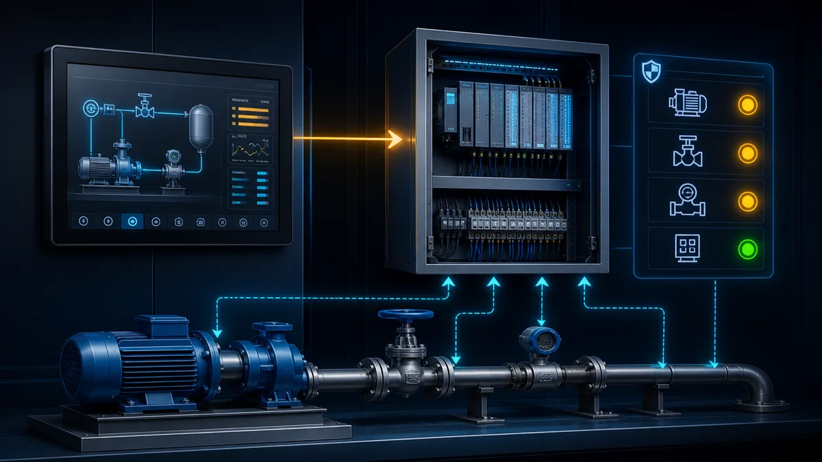
A maintainable PLC–HMI program treats the interface between projects as a versioned contract. The HMI may request an action or propose a setpoint. The PLC validates mode, permissives, interlocks, ownership, range and sequence state before changing an output. The HMI then displays independent PLC and field feedback—not the value it most recently wrote—as the result.
Define the tag contract before drawing screens
Create one row for every value that crosses the interface. Record its source of truth, data type, direction, engineering unit, valid range, update expectation, bad-quality presentation, access role and test case. Keep raw I/O and internal rung bits out of the display contract unless there is a documented diagnostic need. Stable equipment structures make reusable faceplates and automated tag imports safer than hundreds of hand-typed addresses.
| Contract group | Example member | Direction | Owner and acceptance rule |
|---|---|---|---|
| command request | Pump101.Cmd.Start |
HMI → PLC | PLC consumes or rejects; a write alone never proves motion |
| command identity | Pump101.Cmd.Sequence |
HMI → PLC | new sequence distinguishes a fresh request from a stale retained bit |
| command result | Pump101.Cmd.Accepted and reason |
PLC → HMI | PLC reports accepted, rejected, completed or timed out explicitly |
| equipment state | Pump101.State |
PLC → HMI | derived from controller sequence and verified field feedback |
| availability | Pump101.Available and reason mask |
PLC → HMI | summary is convenient; reason data remains diagnosable |
| process value | Pump101.FlowPV plus quality and unit |
PLC/data service → HMI | display never presents stale/bad quality as a healthy live value |
| alarm condition | Pump101.NoFlowAlarm |
PLC/alarm service → HMI | alarm exists only after rationalised cause, consequence and response |
| maintenance data | runtime, starts, diagnostic code | PLC → HMI | update rate and reset permissions are documented and tested |
Choose a command handshake that survives disconnects
Siemens' current Automation Framework describes both a set/reset scheme, in which the HMI sets a command and the PLC resets it after processing, and an OnPressed scheme, in which the command exists only while the control is pressed. The documentation notes different tradeoffs, including reliable processing versus extra logic and deadlock risk for set/reset. A production design must also consider scan timing, network loss, HMI restart, multiple clients and who clears a stale request.
For consequential actions, a sequence-based request can make ownership explicit. The HMI writes the requested action and increments a command sequence. The PLC detects a new sequence, snapshots the request, validates it once, publishes an acknowledgement with the same sequence and reports the result. This is a vendor-neutral design pattern, not code to paste blindly into a safety function.
| Command state | PLC decision | HMI presentation | Required test |
|---|---|---|---|
| no new sequence | ignore retained request fields | neutral/ready | HMI reconnect does not replay an old action |
| new valid request | accept and execute through normal PLC state logic | requested, then accepted/in progress | one short write is not missed |
| new invalid request | reject without driving output; publish reason | rejected with actionable reason | unavailable mode and interlock cases |
| accepted but no field feedback | time out through PLC diagnostic logic | mismatch/failed, never falsely running | contactor, drive or process feedback withheld |
| duplicate sequence | do not execute twice | show existing result | retry and network duplication test |
| client loses connection | finish or abort according to written control philosophy | bad quality/unknown state | cable pull during each command phase |
For arrays, recipes or blocks of related values, use the platform's documented consistency mechanism. Siemens WinCC Unified V21, for example, documents automatic handshake tags for coordinated array reads or writes and notes that simultaneous read and write are not possible during that handshake. Do not assume a group of independently updated tags forms an atomic transaction.
Chapter 1: HMI Fundamentals and Design Principles

Understanding HMI Architecture
HMI systems serve as the primary interface between human operators and automated control systems, translating complex process data into understandable visual representations while providing intuitive control mechanisms for process manipulation. The architecture typically consists of HMI software running on industrial computers or panel PCs connected to PLCs and other control devices through various communication protocols.
Client-server architectures enable multiple operator stations to access the same process data while maintaining centralized data management and security control. This distributed approach improves system reliability and enables operators to monitor and control processes from multiple locations within the facility.
Tag database management forms the foundation of HMI systems, organizing process variables, alarms, and historical data in logical structures that facilitate efficient data exchange with control systems while supporting advanced features such as trending, reporting, and recipe management.
Communication interfaces connect HMI systems to PLCs, SCADA systems, databases, and enterprise networks through standardized protocols such as OPC, Modbus, Ethernet/IP, and Profinet, enabling seamless data exchange while maintaining appropriate security boundaries.
Human Factors Engineering Principles
Effective HMI design follows established human factors engineering principles that optimize operator performance while minimizing errors and fatigue. Visual hierarchy guides operator attention to the most important information while maintaining awareness of overall system status through effective use of color, contrast, and layout principles.
Cognitive load management ensures that operators can process information efficiently without being overwhelmed by excessive detail or complexity. This requires careful organization of information, appropriate use of graphics and symbols, and logical navigation structures that match operator mental models of the process.
Situational awareness design principles help operators understand current process status, anticipate future conditions, and respond appropriately to changing situations. This includes effective alarm management, trend visualization, and integration of predictive information that enables proactive rather than reactive operation.
Consistency in design elements, navigation methods, and interaction patterns reduces operator training requirements while improving response time during normal and emergency operations. Standardized symbols, colors, and procedures across all HMI screens create predictable interfaces that operators can use confidently.

Safety and Security Considerations
An HMI may display safety status, but the display is not automatically part of a safety function. Protective functions require a risk assessment and the appropriate safety-related control architecture. Loss of the HMI or its network must not defeat required risk reduction; emergency-stop and guard behavior belongs in the engineered safety system.
Cybersecurity controls depend on the architecture and risk assessment. Common controls include named accounts, least privilege, application allowlisting where supported, network segmentation, protected remote access, backup/restore testing, patch governance, and logging. Follow the site OT-security program rather than assuming one feature makes a panel secure.
Alarm management philosophy prevents alarm floods that can overwhelm operators during process upsets while ensuring that critical alarms receive appropriate attention. This includes alarm prioritization, acknowledgment requirements, and documentation of operator responses.
Regulated projects may add record, signature, audit, retention, or validation requirements. The required controls depend on jurisdiction and intended use; a vendor feature list alone does not establish compliance.
HMI vs SCADA — What's the Difference?
HMI and SCADA are related but distinct concepts. Understanding the difference is essential before choosing your development platform.
| Feature | HMI | SCADA |
|---|---|---|
| Scope | Operator interaction with a machine or process | Supervisory monitoring and control across distributed assets |
| Data | May include live values, alarms, recipes, and local history | Commonly includes collection, history, alarms, and system-wide context |
| Architecture | Panel, industrial PC, workstation, or web client | Communications, servers/gateways, data services, and one or more HMI clients |
| Alarms | Can implement a complete alarm interface | Often manages alarms across multiple controllers or sites |
| Remote access | Product and architecture dependent | Product and architecture dependent |
| Commercial model | Depends on panel, runtime, tags, clients, and support | Depends on server, clients, tags, modules, history, and redundancy |
| Example | Operator panel on a packaging machine | Supervisory system monitoring an entire water treatment plant |
Key distinction: HMI describes the human-facing interface; SCADA describes a supervisory system architecture that normally includes HMI clients plus communications and data services. Product boundaries overlap, so classify the required architecture before choosing a license.
Learn more: See our complete SCADA tutorial for a deep dive into SCADA architecture and implementation.
Common HMI software ecosystems
This is an orientation table, not a ranking or a promise of current licensing. Verify supported controller families, drivers, panel models, operating systems, deployment targets, and license terms with the vendor before selecting a platform.
| Platform family | Vendor | Typical ecosystem fit | What to verify |
|---|---|---|---|
| FactoryTalk View | Rockwell Automation | Logix and PanelView projects | ME/SE edition, supported firmware, driver path |
| WinCC | Siemens | SIMATIC and TIA Portal projects | Unified/Professional/Comfort target and license |
| Ignition | Inductive Automation | Server-based, web-delivered architectures | Required modules, drivers, gateway sizing |
| AVEVA HMI/SCADA products | AVEVA | Machine through plant-level visualization | Current product name, deployment model, drivers |
| EcoStruxure operator-interface tools | Schneider Electric | Modicon and Schneider HMI projects | Panel generation, replacement path, protocols |
| CODESYS Visualization | CODESYS ecosystem | CODESYS controller/runtime projects | Target visualization type and runtime license |
| EasyBuilder Pro | Weintek | Weintek operator panels | Exact panel support and protocol driver |
Need a current shortlist? Use the HMI software comparison, then confirm every finalist against the vendor's current compatibility and licensing documentation.
Chapter 2: HMI Programming Software and Development Platforms
HMI platform selection boundaries
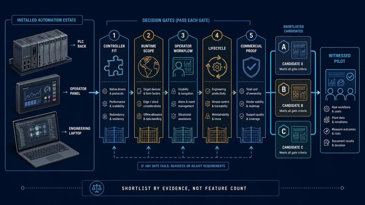
Do not choose from a feature checklist alone. Shortlist platforms against the installed PLCs, required protocols, supported panels or operating systems, cybersecurity architecture, alarm/historian responsibilities, source-control and backup workflow, lifecycle support, and the skills of the people who will troubleshoot the system.
Require a proof-of-fit project before purchase: connect one representative PLC, build one faceplate, exercise alarm acknowledgment and history, test user roles, restore from backup, and measure behavior during a communications interruption. A platform that passes that test on your target versions is a stronger choice than one with a longer marketing feature list.
Step-by-Step HMI Programming Environment Setup
Step 1: Project Configuration
- Define communication drivers for your PLC systems (Ethernet/IP, Modbus, Profinet)
- Set up tag databases with proper naming conventions and data types
- Configure alarm systems with appropriate priority levels and acknowledgment requirements
- Establish user management settings with role-based access control
Step 2: Graphics Development Environment
- Create process graphics using standard ISA symbols and consistent color schemes
- Develop reusable symbol libraries for common equipment (pumps, valves, motors)
- Implement faceplates and navigation elements that form the visual interface
- Utilize object-oriented graphics with inheritance, animation, and dynamic property binding
Step 3: HMI Programming and Scripting
- Implement custom functionality using VBScript, C#, or proprietary scripting languages
- Create calculation routines and integration with external systems
- Develop event-driven programming for operator interactions and system responses
- Build error handling and diagnostic routines for robust operation
Step 4: Testing and Simulation Setup
- Configure simulation environments to validate HMI functionality without physical PLCs
- Create test scenarios for all operational modes and alarm conditions
- Develop operator training simulations and documentation
- Implement automated testing procedures for system validation
Database Integration and Connectivity
OPC (OLE for Process Control) connectivity provides standardized communication between HMI systems and control devices from different manufacturers while maintaining vendor independence and system flexibility. Understanding OPC server configuration and client programming is essential for modern HMI development.
SQL database connectivity enables HMI systems to store and retrieve historical data, recipes, user information, and configuration parameters through standard database interfaces. This capability is essential for regulatory compliance and advanced analytics applications.
Web service integration allows HMI systems to exchange data with enterprise systems, cloud services, and mobile applications through RESTful APIs and web services, enabling Industry 4.0 connectivity while maintaining security requirements.
File system integration supports import/export of recipes, reports, and configuration data while enabling backup and restore operations that maintain system availability and data integrity.
Live mini-lab
Try it: press START, then STOP
A stop-dominant seal-in rung: START latches the motor output through its own contact, and STOP breaks the circuit.
Watch the output lamp: it stays on after START until you press STOP.
Free to start · runs in your browserOpens plcsimulationsoftware.com — same team
Chapter 3: HMI Graphics Programming and Animation
Creating Effective HMI Programming Graphics
HMI Programming Graphics Design Principles Graphic design principles for industrial HMI programming applications emphasize clarity, consistency, and functionality over aesthetic appeal. Process graphics in HMI programming should accurately represent physical equipment and process flow while providing clear indication of operating status and control capabilities.
Standard Symbol Libraries for HMI Programming Symbol libraries and standardization ensure consistent representation of common equipment types such as pumps, valves, tanks, and motors across all HMI programming screens. Many HMI programming platforms provide extensive symbol libraries that comply with ISA standards for instrumentation and control graphics.
HMI Programming Color Coding Strategies
- Green: Normal operation, equipment running
- Red: Alarm conditions, equipment faulted
- Yellow/Amber: Warning states, maintenance required
- Gray: Equipment offline or disabled
- Blue: Manual mode or operator control active
Layout Principles for HMI Programming Layout and composition principles organize screen elements logically while maintaining visual balance and clear information hierarchy. Effective HMI programming layouts guide operator attention to important information while providing easy access to control functions through intuitive navigation structures.
Dynamic Animation and Data Binding
Data binding connects graphic elements to real-time process data through tag references that automatically update visual properties such as color, size, position, or visibility based on current process conditions. Understanding data binding is fundamental to creating responsive HMI graphics.
Animation techniques include rotation, translation, scaling, and color changes that provide visual feedback about equipment operation and process status. Effective animation enhances operator understanding without creating distracting or confusing visual effects.
Conditional formatting automatically adjusts graphic appearance based on data values, alarm states, or calculated conditions. This capability enables graphics to provide rich information about process conditions without requiring operator interpretation of numerical values.
Real-time updates ensure that HMI graphics accurately reflect current process conditions with appropriate update rates that balance information currency with system performance. Understanding update mechanisms is essential for creating responsive HMI applications.
Advanced Graphics Features
3D graphics and visualization provide enhanced representation of complex equipment and processes while maintaining clarity and functionality. Modern HMI platforms support 3D graphics that improve operator understanding of spatial relationships and equipment orientation.
Video integration enables HMI systems to display camera feeds, recorded video, and streaming content within process graphics or dedicated video windows. This capability is particularly valuable for security, quality control, and remote monitoring applications.
Custom graphics development using vector drawing tools, imported CAD drawings, or third-party graphics software enables creation of specialized graphics that accurately represent unique equipment or processes not available in standard symbol libraries.
Multi-monitor support allows HMI applications to span multiple displays while maintaining logical organization and navigation. This capability is essential for complex control rooms and operator stations requiring extensive process visualization.

Chapter 4: Alarm Management and Event Handling
Alarm System Design
Alarm philosophy development establishes the principles and criteria for determining what conditions warrant operator notification while avoiding alarm floods that can overwhelm operators during process upsets. Effective alarm philosophy balances completeness with manageable alarm rates.
Alarm prioritization systems organize alarms by importance and urgency, enabling operators to focus on the most critical conditions first while maintaining awareness of less critical issues. Priority levels typically include critical, high, medium, and low categories with different notification methods.
Alarm states and transitions define the lifecycle of alarm conditions including normal, alarm, acknowledged, and shelved states. Understanding alarm state management is essential for implementing effective operator notification and response tracking systems.
Performance monitoring and optimization involve measuring alarm system effectiveness through metrics such as alarm rates, response times, and operator acknowledgment patterns. Regular alarm system analysis identifies opportunities for improvement and prevents alarm system degradation.

Event Processing and Logging
Event detection and filtering identify significant process events while eliminating nuisance alarms and routine operational events that do not require operator attention. Effective filtering reduces operator workload while ensuring important events receive appropriate attention.
Historical event storage maintains records of all alarms and events for regulatory compliance, troubleshooting, and performance analysis. Event logging must balance data retention requirements with storage capacity and system performance considerations.
Event correlation and analysis identify patterns and relationships between events that may indicate developing problems or provide insights into process behavior. Advanced event analysis can support predictive maintenance and process optimization initiatives.
Reporting and documentation capabilities generate alarm summaries, performance reports, and compliance documentation required for regulatory reporting and management review. Automated reporting reduces administrative burden while ensuring consistent documentation.
Operator Response and Documentation
Acknowledgment requirements ensure that operators are aware of alarm conditions and have taken appropriate action. Acknowledgment strategies must balance operator workload with the need for documented operator awareness and response.
Response documentation captures operator actions, comments, and decisions related to alarm conditions. This documentation is essential for regulatory compliance, incident investigation, and continuous improvement of alarm management practices.
Escalation procedures automatically notify supervisors or maintenance personnel when operators do not respond to critical alarms within specified time limits. Escalation systems ensure that critical conditions receive appropriate attention even when operators are unavailable.
Training and competency management ensure that operators understand alarm system operation and respond appropriately to different alarm conditions. Regular training and assessment maintain operator proficiency and system effectiveness.
Chapter 5: Data Management and Historical Trending
Real-Time Data Handling
Data acquisition strategies optimize the collection and processing of real-time process data while managing communication bandwidth and system performance. Effective data acquisition balances information currency with system efficiency through appropriate sampling rates and data compression techniques.
Tag organization and naming conventions create logical data structures that facilitate development, maintenance, and troubleshooting while supporting advanced features such as automated graphics generation and standardized templates.
Data validation and quality assessment ensure that displayed information is accurate and reliable through range checking, rate-of-change limits, and communication status monitoring. Data quality indicators help operators understand the reliability of displayed information.
Performance optimization techniques minimize system resource usage while maintaining responsive operation through efficient data structures, optimized communication protocols, and intelligent data caching strategies.
Historical Data Storage and Retrieval
Historian integration enables long-term storage and retrieval of process data for trending, analysis, and regulatory compliance. Understanding historian configuration and data retrieval methods is essential for implementing effective data management strategies.
Data compression and archiving strategies balance data resolution with storage capacity requirements while maintaining access to historical information needed for analysis and compliance reporting. Automated archiving procedures ensure continued system operation without manual intervention.
Trend analysis capabilities enable operators and engineers to identify patterns, diagnose problems, and optimize process performance through visualization of historical data relationships. Effective trending tools support both real-time monitoring and historical analysis.
Data export and integration features enable sharing of historical data with other systems, analysis tools, and reporting platforms. Standard export formats and API access facilitate integration with enterprise systems and specialized analysis software.
Recipe and Batch Management
Recipe development and management systems organize formulations, procedures, and parameters for batch manufacturing processes while maintaining version control and audit trails required for regulatory compliance and quality assurance.
Batch tracking and genealogy maintain complete records of materials, parameters, and events for each batch or lot produced. This information is essential for quality control, regulatory compliance, and traceability requirements.
Parameter management ensures that recipe parameters are correctly applied to control systems while maintaining security and change control procedures that prevent unauthorized modifications to production formulas.
Reporting and documentation generate batch records, quality reports, and compliance documentation required for regulatory submission and quality management systems. Automated documentation reduces errors while ensuring consistent record keeping.
Chapter 6: Scripting and Advanced Programming
Scripting Language Fundamentals
VBScript programming provides extensive customization capabilities for HMI applications through event-driven scripting that responds to operator actions, data changes, and system events. Understanding VBScript syntax and programming concepts is essential for advanced HMI development.
Variable management and data types enable scripts to process and manipulate data while maintaining appropriate data typing and scope control. Proper variable management prevents memory leaks and ensures reliable script operation.
Control structures including conditional statements, loops, and error handling enable sophisticated logic implementation while maintaining code reliability and maintainability. Understanding control structures is fundamental to effective script development.
Object-oriented programming concepts enable creation of reusable code modules and standardized interfaces that improve development efficiency while maintaining consistency across HMI applications.
Communication and Integration Programming
Database programming enables HMI applications to read and write information from SQL databases, historian systems, and other data sources through ADO, ODBC, or native database interfaces. Database programming is essential for advanced data management and reporting capabilities.
Web service integration allows HMI systems to exchange data with enterprise systems, cloud services, and mobile applications through programmatic interfaces that maintain security and data integrity requirements.
File system operations enable HMI applications to import/export data, generate reports, and manage configuration files through programmatic file manipulation capabilities. Understanding file operations is important for automated data management tasks.
Communication protocol programming enables custom communication with specialized devices or systems that do not support standard industrial protocols. This capability extends HMI connectivity to unique or legacy systems.
Error Handling and Debugging
Exception handling ensures that scripts continue operating reliably even when unexpected conditions occur. Proper error handling prevents script failures from affecting HMI operation while providing appropriate notification of problems.
Debugging techniques including breakpoints, variable monitoring, and step-through execution enable developers to identify and correct script problems efficiently. Understanding debugging tools is essential for script development and maintenance.
Logging and diagnostics provide visibility into script operation and performance while identifying potential problems before they cause system failures. Systematic logging facilitates troubleshooting and performance optimization.
Performance optimization techniques minimize script execution time and resource usage while maintaining functionality. Script optimization becomes important for applications with extensive custom programming or high-frequency operations.
Chapter 7: Web-Based and Mobile HMI Development
Web HMI Architecture
Web-based HMI systems enable operators to access process information and control capabilities through standard web browsers while maintaining security and performance requirements. Understanding web HMI architecture is essential for modern industrial applications.
HTML5 and responsive design techniques ensure that HMI applications function effectively across different devices and screen sizes while maintaining usability and functionality. Responsive design is particularly important for mobile device support.
Security considerations for web-based HMI systems include authentication, encryption, and access control measures that protect industrial systems from cyber threats while enabling legitimate remote access capabilities.
Performance optimization for web HMI applications balances rich functionality with responsive operation over various network connections and device capabilities. Understanding web performance factors is important for successful deployment.
Mobile Device Integration
Mobile HMI development enables operators and maintenance personnel to access process information and control capabilities through smartphones and tablets while maintaining security and usability requirements appropriate for industrial environments.
Touch interface design principles optimize HMI applications for touch-based interaction while accommodating the smaller screens and different input methods used by mobile devices. Effective touch interfaces enhance operator productivity and satisfaction.
Offline capability enables mobile HMI applications to continue providing information and limited functionality even when network connectivity is interrupted. This capability is important for maintenance and field operations.
Security and device management ensure that mobile HMI applications maintain appropriate security controls while enabling convenient access to authorized personnel. Mobile device management becomes critical for maintaining security in distributed operations.
Cloud Integration and Analytics
Cloud connectivity enables HMI systems to share data with cloud-based analytics platforms, remote monitoring services, and enterprise systems while maintaining appropriate security controls for industrial data.
Data analytics integration allows HMI systems to display insights and recommendations generated by advanced analytics platforms while maintaining the real-time responsiveness required for process control applications.
Remote monitoring capabilities enable operators and management to access process information from any location while maintaining security and performance appropriate for industrial applications.
Predictive maintenance integration displays equipment health information, maintenance recommendations, and failure predictions generated by advanced analytics systems while enabling operators to take appropriate preventive actions.
Chapter 8: Practical HMI Programming Implementation Examples
Step-by-Step Motor Control HMI Programming Example
Creating a Basic Motor Control Interface
-
Define Tags and Data Points
Motor_Start_Request: BOOL (HMI writes a momentary request) Motor_Stop_Request: BOOL (HMI writes a momentary request) Motor_Running_Feedback: BOOL (HMI reads independent field feedback) Motor_Available: BOOL (HMI reads the PLC's non-safety availability summary) Motor_Faulted: BOOL (HMI reads fault status) Motor_Current_A: REAL (HMI reads scaled current) HMI_Command_Sequence: DINT (optional command/acknowledgment sequence) -
Design the Graphics Screen
- Motor symbol animated from
Motor_Running_Feedback, never from the start request - Start and stop controls that write only the defined request tags
- Availability, running, stopped, faulted, bad-quality, and unknown states
- Current display with engineering units, quality, and a justified trend window
- Alarm access that shows the approved operator response
- Motor symbol animated from
-
Implement Interactive Controls
- PLC logic validates mode and permissives; the HMI does not implement protective interlocks
- Momentary requests time out instead of remaining latched after a disconnect
- Confirmation is reserved for consequential or irreversible actions
- A command/feedback timer detects “requested but did not run”
- Bad or stale data cannot look like a healthy stopped state
-
Execute the acceptance tests
Test Action or injected condition Expected HMI result Normal start Start while available Request pulses; running appears only after feedback Start rejected Start while unavailable PLC rejects command; reason is visible Feedback missing Accept command but withhold feedback Mismatch alarm after approved delay Communications loss Disconnect the PLC session Values show bad/unknown; no false healthy state User-role test Log in without control permission Command controls are unavailable Restart Reboot HMI/runtime No stale request is reissued; screen restores predictably Restore Load the approved backup Correct version, tags, users, and alarms return

Test the PLC–HMI program as a state contract
A screen that works on a healthy bench is not accepted. Inject loss of communication, stale quality, rejected commands, missing field feedback, out-of-range setpoints, role changes and restarts. Observe both sides of the contract: the value in the controller and the object presented to the operator. Screens must not freeze on their last healthy colour or imply that a command succeeded because a button animation changed.
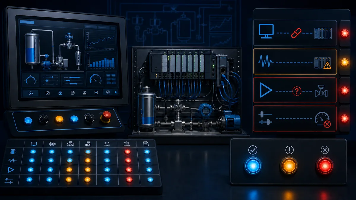
| Injected condition | PLC-side expected state | HMI-side expected state | Evidence retained |
|---|---|---|---|
| communications session lost | deterministic control continues or moves to engineered fallback independent of screen animation | affected values become bad/unknown; write controls follow access philosophy | controller log, HMI diagnostic, timestamped screenshot |
| tag update freezes without full disconnect | quality/heartbeat logic detects staleness where required | stale age or quality is visible and cannot resemble current data | last-update time, quality code and display state |
| start accepted but auxiliary feedback absent | command/feedback timeout and approved alarm activate | requested/running/fault states remain distinct | sequence, timer, feedback and alarm timestamps |
| setpoint below/above limit | PLC rejects or clamps according to specification and reports actual accepted value | rejected proposal and permitted range are clear | proposed, accepted, reason and user identity |
| HMI restarts with retained command bit | PLC does not treat old state as a fresh command | no automatic replay; current equipment truth reloads | sequence/edge evidence before and after restart |
| second HMI issues a command | written ownership/arbitration rule determines result | both clients show the same accepted state and audit context | client identity, sequence and result |
| user role changes | PLC/HMI authorization prevents disallowed write path | prohibited controls unavailable without hiding current state | account, role, audit entry and rejected write |
| controller mode changes | PLC command logic rejects inappropriate remote actions | mode and unavailability reason are prominent | mode tag, reason code and attempted command |
Advanced Pump Station HMI Programming Example
This example demonstrates HMI programming for a multi-pump system with lead/lag control:
Pump1_Run: BOOL
Pump1_Auto: BOOL
Pump1_Fault: BOOL
Pump1_Hours: REAL
System_Pressure: REAL
Flow_Rate: REAL
Tank_Level: REAL
The HMI programming includes:
- System overview with all pumps and process values
- Individual pump control faceplates
- Trending screens for pressure, flow, and level
- Alarm summary and acknowledgment functionality
- Maintenance scheduling based on runtime hours
HMI Programming Best Practices Checklist
✓ Use consistent naming conventions for tags and graphics ✓ Implement proper error handling for all user interactions ✓ Create intuitive navigation with breadcrumb trails ✓ Design for multiple screen resolutions and operator positions ✓ Include comprehensive alarm management and acknowledgment ✓ Implement user access control and audit trails ✓ Provide clear status indication for all equipment ✓ Design screens that minimize operator cognitive load ✓ Test all functionality under simulated fault conditions ✓ Document all custom scripts and programming logic
Chapter 9: Testing, Deployment, and Maintenance
Application Testing Strategies
Functional testing validates that HMI applications perform all required functions correctly while identifying potential problems before deployment in production environments. Systematic testing prevents costly problems and ensures operator confidence.
Performance testing measures HMI application response time, resource usage, and communication performance under various loading conditions to ensure satisfactory operation during normal and peak operations.
Security testing validates that authentication, authorization, and data protection measures function correctly while identifying potential vulnerabilities that could compromise system security.
User acceptance testing involves operators and other end users in validating HMI application functionality, usability, and performance to ensure that the system meets operational requirements and user expectations.
Deployment and Installation
Installation procedures ensure that HMI applications are deployed correctly while maintaining system security and minimizing disruption to ongoing operations. Systematic installation procedures prevent configuration errors and deployment problems.
Configuration management maintains consistent application settings across multiple installations while enabling appropriate customization for specific operational requirements. Configuration management becomes critical for multi-site deployments.
Backup and recovery procedures ensure that HMI applications and data can be restored quickly in the event of system failures or corruption. Regular backup validation ensures that recovery procedures function when needed.
Documentation and training ensure that operators and maintenance personnel understand HMI application operation and can use the system effectively. Complete documentation facilitates troubleshooting and system maintenance.
Ongoing Maintenance and Support
Preventive maintenance procedures maintain HMI system performance and reliability through regular updates, database maintenance, and hardware inspection. Preventive maintenance prevents problems while extending system life.
Performance monitoring identifies developing problems and optimization opportunities through systematic measurement of response time, resource usage, and user satisfaction metrics. Ongoing monitoring enables proactive maintenance and improvement.
Change management procedures ensure that HMI application modifications are implemented safely while maintaining system integrity and documentation currency. Proper change management prevents problems while enabling system improvement.
User support and training programs maintain operator proficiency while addressing questions and problems that arise during system operation. Ongoing support ensures continued system effectiveness and user satisfaction.
Conclusion: ship an HMI that communicates state truthfully
A useful HMI makes the actual process state, data quality, available actions, and abnormal conditions legible. Its quality is demonstrated by task analysis, command/feedback tests, alarm rationalization, disconnect behavior, access-control tests, backup restoration, and operator acceptance—not by animation count.
Successful HMI programming requires combining technical programming skills with human factors engineering knowledge and deep understanding of industrial processes and operational requirements. This multidisciplinary approach creates interfaces that truly enhance operator capability and system performance.
Related PLC Programming Resources
To expand your automation expertise beyond HMI programming, explore these essential topics:
- Ladder Logic Programming Fundamentals - Master the foundation of PLC programming
- PLC Communication Protocols - Learn how to integrate HMI systems with various industrial networks
- Structured Text Programming - Advanced programming techniques for complex HMI logic
- Free PLC Programming Software - Find the right development tools for your HMI programming projects
Continue with a runnable PLC–HMI example
Build the motor faceplate above, execute the acceptance matrix, and record the failures you discover. Then repeat the same component contract for a valve, analog loop and sequence overview. The page CTA opens a browser training path for the PLC-side state and diagnostic logic; it does not imitate a specific commercial HMI editor or claim to validate an installed control system.
Diagnostic answer map for search and AI-assisted implementation
| Expanded query | Direct answer surface |
|---|---|
| How do I make a PLC HMI program? | define operator tasks and a tag contract, implement commands as PLC-validated requests, bind screens to independent state/feedback, then test normal and failed communication states |
| Should control logic be programmed in the PLC or HMI? | deterministic equipment, interlock and protective logic belongs in the appropriate controller/safety system; the HMI requests actions and presents state |
| What tags are needed for an HMI start/stop screen? | separate request, accepted/result, availability/reason, equipment state, independent running feedback, fault, quality and relevant process values |
| How should an HMI button handshake with a PLC? | choose a documented momentary, set/reset or sequence/acknowledgement pattern and test disconnect, restart, duplicate and multi-client cases |
| How do I prevent an HMI command from sticking on? | avoid treating a retained level as a new action; use controlled reset, timeout or sequence identity and test communication loss during every command phase |
| What should the HMI display when PLC data is stale? | show bad/unknown or stale quality and age explicitly; never leave the last healthy color looking current |
| How do I program reusable HMI faceplates? | bind a stable equipment structure containing commands, state, mode, availability, reasons, feedback, alarms and diagnostics rather than raw I/O addresses |
| How are HMI setpoints validated? | the HMI constrains entry for usability, while the PLC independently validates authority, range, rate and operating state and returns the accepted value or rejection reason |
| How do I test a PLC and HMI program together? | inject communication loss, stale values, rejected commands, missing feedback, restarts, user-role changes and multiple clients against a written matrix |
| How is PLC–HMI communication different from HMI screen programming? | this owner covers the complete program and operator task; the dedicated communication guide owns connection setup, tag transport, handshakes and network fault isolation in depth |
Frequently asked questions
Does the HMI control the machine or does the PLC?
The PLC or appropriate safety/control system owns deterministic equipment logic, permissives, interlocks, sequencing and outputs. The HMI is an operator interface: it submits authorised requests, displays controller and field state, manages supported alarm interactions and presents diagnostics. Loss of the HMI must not silently bypass required risk reduction or sustain hazardous motion.
What is a PLC–HMI tag contract?
It is the documented interface between controller and display projects. For each exchanged value it defines name, structure, data type, direction, source of truth, unit, range, update/quality behavior, write authority and acceptance tests. A stable contract prevents screens from depending on transient internal bits or unversioned physical addresses.
Should an HMI start button write directly to a PLC output?
No. It should write a command/request interface. PLC logic then checks mode, ownership, permissives, interlocks and sequence state before controlling the output. The running indication should come from controller state and preferably independent field feedback, not from the request bit or button animation.
Is a momentary HMI button always safe from a stuck command?
No. Network interruption, missed release events, client restart and scan timing can make assumptions about a press/release pair fail. Use a documented platform pattern and PLC-side timeout, edge or sequence handling appropriate to the action. Test disconnect and restart at every phase; do not apply a generic pattern to a safety function.
When should a PLC–HMI command use an acknowledgement?
Use acknowledgement when the application must distinguish receipt, acceptance, rejection, progress or completion, especially for requests that cross a network or can be retried. Include request identity such as a sequence where needed. Simple local momentary actions may use a smaller pattern, but still require command/feedback testing.
Where should HMI setpoint limits be enforced?
Use HMI entry limits and units to help the operator, but enforce the authoritative range, user permission and process-state rules in the PLC or responsible application service. Return the accepted value or a clear rejection reason. Do not assume a client-side widget protects the controller from another client or malformed write.
What should happen on PLC–HMI communication loss?
Controller behavior follows the engineered control philosophy and must not depend on a decorative screen state. The HMI should expose bad or unknown quality, disable or qualify writes according to the access design, preserve actionable diagnostics and recover without replaying stale commands. Test partial loss as well as a clean disconnect.
How many screens should an HMI program have?
There is no universal count. Use the minimum hierarchy that supports the documented operator tasks: typically overview, area/unit detail, equipment faceplates, alarm access, trends and diagnostics. Measure navigation paths, abnormal-task performance and display load instead of optimising for screen quantity.
Do I need an alarm for every PLC fault bit?
No. An alarm requires a condition that needs timely operator awareness and response. Rationalise cause, consequence, corrective action, priority, deadband and shelving/suppression rules under the site alarm philosophy. Many diagnostic conditions belong in status or maintenance views rather than the alarm list.
Can I test an HMI program without the real machine?
You can test tag binding, navigation, command-state logic, bad-quality presentation, alarm behavior and many failure cases with controller/HMI simulation or a hardware-in-the-loop bench. That does not reproduce every driver, panel, field device, network, process or safety behavior. Final acceptance must use the approved target versions and witnessed site test plan.
Sources, review scope, and limitations
Official primary sources reviewed
- ISA-101 series — Human-Machine Interfaces, accessed 2026-08-29. Used for HMI lifecycle, philosophy, style-guide, design, implementation, operation and continuous-improvement context.
- ISA-18 series — Instrument Signals and Alarms, accessed 2026-08-29. Used for alarm lifecycle and rationalisation boundaries.
- Siemens Automation Framework V2.2 — PLC–HMI handshake, publication 2026-04, accessed 2026-08-29. Used for current set/reset and pressed-command patterns and their tradeoffs.
- Siemens WinCC Unified V21 — Configuring an automatic handshake, publication 2026-03, accessed 2026-08-29. Used for array read/write handshake and concurrency limitations.
- Siemens — Communication with SIMATIC controllers, accessed 2026-08-29. Used for external-tag and controller communication context; verify current product edition.
- Rockwell Automation — FactoryTalk View Machine Edition User's Guide, accessed 2026-08-29. Used for a current vendor-family implementation boundary covering tags, displays, security and runtime workflow.
- Ignition 8.3 User Manual, accessed 2026-08-29. Used for current gateway, tag, alarming, security and project architecture context.
- OPC Foundation — OPC UA specifications, accessed 2026-08-29. Used for information-model, subscription, quality/status and security reference boundaries.
- NIST SP 800-82 Rev. 3 — Guide to Operational Technology Security, published 2023-09, accessed 2026-08-29. Used for OT architecture, least-functionality, remote-access and risk-management context.
- CISA — Configuring and Managing Remote Access for Industrial Control Systems, accessed 2026-08-29. Used for remote HMI/ICS access boundaries.
Scope and implementation limits
This page is vendor-neutral education and a test framework. It is not a certified HMI design, alarm philosophy, safety function, cybersecurity architecture, validated regulated-system procedure or substitute for the exact platform manuals and site standards. Product names, editions, licensing, drivers, scripting APIs, tag limits, panel firmware and browser/runtime support change. Confirm the target matrix and retain a tested backup before release.
The example tags and handshake states illustrate interface responsibilities; they are not paste-ready control or safety code. Qualified personnel must perform the process hazard/risk assessment, assign control and safety functions, approve accounts/network access, witness abnormal-state tests and authorise deployment. The two new generated figures are conceptual editorial illustrations, not vendor screenshots or validated screen designs.
Now run it · free to start
Build an HMI screen in your browser
Design operator screens from tags, pushbuttons and pilot lamps up to alarms and trends in a browser HMI builder. Free to start, nothing to install.
Ownership disclosure: PLC Programming IO and PLC Simulation Software are operated by the same publisher.