Modbus Register Mapping and Addressing Explained
Map Modbus coils and registers correctly with zero-based PDU offsets, one-based reference notation, function codes, data widths, word order, scaling and tested polling blocks.
Review status: Editorially reviewed against cited Modbus Organization, Siemens, CODESYS, Schneider Electric and Weintek documentation; exact implemented ranges, driver syntax, data representation and access require endpoint-specific verification
Direct answer
Modbus register mapping is the controlled translation from a device's
published process variables into the logical Modbus table, zero-based protocol
offset, client-facing address, width, data type, word order, scale, units,
access and validation evidence. A usable map records all of those fields; a
spreadsheet containing only labels and 4xxxx numbers is not enough to prove
that an HMI, PLC, gateway or SCADA system will decode the same value correctly.
Modbus has four logical data blocks: coils (one-bit read/write), discrete inputs (one-bit read-only), input registers (16-bit read-only) and holding registers (16-bit read/write in the protocol model). A Modbus request selects the block through its function code and carries a zero-based 16-bit starting address from 0 to 65535. The wire frame does not carry the human prefixes 0xxxx, 1xxxx, 3xxxx or 4xxxx.
The common reference 40001 means “the first holding-register element” in one-based human notation, so its PDU offset is normally 0. Likewise, reference 40100 normally corresponds to holding-register offset 99. But client drivers vary: one may ask you to enter 40001, another 1, another 0, and another a table plus offset. Always record the logical table, one-based documentation reference, zero-based PDU offset and exact client-tool address string separately, then prove the translation with one distinctive known value.
Every register contains exactly 16 bits. Signedness, engineering scale, bit meaning, text encoding and the ordering of words in a 32- or 64-bit value are device-specific. The protocol specifies byte transmission rules for its fields and 16-bit register values; it does not standardize a universal cross-register float order. A correct map therefore needs function, offset, width, representation, word order, access, units, scale, limits, quality and version—not just a number such as 40125.

Understand the four Modbus data blocks
The Modbus application specification describes a data model composed of four blocks. It also permits a device to map those blocks independently or onto overlapping application memory. That flexibility is useful, but it means the protocol name does not reveal the PLC variable, terminal or process meaning behind a location.
Data blocks, access and common functions
| Data block | Element width | Protocol-model access | Common read function | Common write functions | Legacy reference family |
|---|---|---|---|---|---|
| coils | 1 bit | read/write | 01 | 05 single, 15 multiple | 00001… / 0xxxx |
| discrete inputs | 1 bit | read-only | 02 | none in standard data model | 10001… / 1xxxx |
| input registers | 16 bits | read-only | 04 | none in standard data model | 30001… / 3xxxx |
| holding registers | 16 bits | read/write | 03 | 06 single, 16 multiple, 22 mask, 23 read/write where supported | 40001… / 4xxxx |
“Read-only” describes protocol access to input/discrete blocks. The device application itself updates them from I/O, calculations or internal state. “Read/write” does not mean every holding register accepts writes in a real device: a manufacturer can expose status through FC03 but reject writes, reserve ranges or require an operating state/password. The installed device map is authoritative.
Function code is part of the address
Offset 10 in coils and offset 10 in holding registers are different items because FC01 and FC03 select different blocks. A client interface that asks only for “address 10” must also store a table or function selection somewhere. Diagnose the function and offset together.
| Intended operation | Request concept | Typical failure when wrong |
|---|---|---|
| read run-permissive bit published as coil offset 10 | FC01, start 10, quantity 1 | FC02 may return a different discrete input or exception |
| read temperature at input-register offset 10 | FC04, start 10, quantity/width from map | FC03 can return holding data at same offset or exception |
| read setpoint at holding-register offset 10 | FC03, start 10, quantity 1+ | FC04 reads the wrong table even if client shows “register 10” |
| write one command word at holding offset 10 | FC06 if endpoint permits | writing a status-only register returns exception or has no effect |
| write coherent block | FC16 or product-supported transactional method | several FC06 writes can expose a partial parameter set |
For detailed function limits and exception diagnosis, use the Modbus function and exception code guide. This page focuses on turning a device register list into correct client addresses and typed values.
Modbus address range and address format
The Modbus address range in a request is 0 through 65535 (0x0000 through 0xFFFF) because the PDU starting-address field is 16 bits. That range exists separately inside each logical data block selected by the function code; holding-register offset 10 is not the same item as input-register offset 10. It is also only a protocol ceiling: the protocol range is not proof a server implements every offset. A real server may implement a few dozen or a few thousand non-contiguous locations, and every requested address must exist for the selected function and firmware map.
The Modbus address format shown to an engineer is not standardized to one universal entry string. Classic five-digit references such as 40001 identify a logical block and one-based element, extended six-digit references such as 400001 can expose more of the 16-bit range, and many current clients ask for a table plus raw offset. The prefix belongs to documentation or driver syntax, not to the PDU address field.
| Address layer | Example or range | Meaning | Boundary to verify |
|---|---|---|---|
| PDU starting address | 0…65535 / 0x0000…0xFFFF |
Zero-based 16-bit offset within the block selected by the function | Start plus quantity minus one must remain representable and implemented |
| Classic five-digit holding reference | 40001…49999 |
Common one-based display convention; 40001 normally maps to PDU offset 0 |
It displays only part of the possible 16-bit offset space and is not sent on the wire |
| Extended six-digit holding reference | 400001…465536 |
Vendor/tool convention that can display all 65,536 holding-register elements | Confirm the manual uses this exact convention; some tools parse six digits differently |
| Table plus offset | Holding, offset 0…65535 |
The client stores the logical block separately and exposes the raw relative offset | Confirm whether a “zero-based addressing” option adds or subtracts one |
| Device register map | For example, offsets 0…127 and 256…319 |
Locations actually implemented by this product and firmware | Reserved gaps, access, width and function-specific quantity limits still apply |
For a Modbus holding-register address range, do not assume 40001…49999 is a protocol limit or that all 65,536 potential offsets exist. Determine the driver's input format, translate it to FC03/FC06/FC16 plus a zero-based start, calculate the final offset, then test the implemented first, last, adjacent and outside locations. An exception code 02 indicates the server rejected the requested address combination; use the exception-code owner when the diagnostic task—not notation—is primary.
Translate human references to PDU offsets
The Modbus specification makes an important distinction: data-model elements are numbered from 1 to n, while addresses inside the Protocol Data Unit are 0 through 65535. That creates the common minus-one translation.
Use the formula only after identifying notation

For classic five-digit one-based references:
- coil PDU offset = reference −
00001 - discrete-input PDU offset = reference −
10001 - input-register PDU offset = reference −
30001 - holding-register PDU offset = reference −
40001
| Documentation item | Logical block | One-based reference | PDU offset decimal | PDU offset hex |
|---|---|---|---|---|
| first coil | coils | 00001 |
0 | 0x0000 |
| sixteenth coil | coils | 00016 |
15 | 0x000F |
| first discrete input | discrete inputs | 10001 |
0 | 0x0000 |
| first input register | input registers | 30001 |
0 | 0x0000 |
| one-hundredth input register | input registers | 30100 |
99 | 0x0063 |
| first holding register | holding registers | 40001 |
0 | 0x0000 |
| one-hundredth holding register | holding registers | 40100 |
99 | 0x0063 |
Do not apply these formulas blindly to any number printed in a device manual. A column labeled Address, Offset, Protocol address, Register, PLC address, Hex or Index can use different bases and formats. A manufacturer may publish raw offsets beginning at 0 or 1, six-digit references such as 400001, hexadecimal offsets, word numbers inside a file, or a protocol-independent internal parameter number.
Decode the documentation before configuring the client
| Register-list clue | Likely interpretation | Confirmation |
|---|---|---|
table heading says holding registers and first row is 0 |
probably zero-based PDU offset | function and example request in manual |
first row is 1, no 4 prefix |
possibly one-based element number | subtract-one note or client example |
first row is 40001 |
classic one-based holding reference | manual's driver-specific addressing note |
first row is 400001 |
six-digit holding reference for larger visible range | vendor convention and tool entry example |
values like 0x0100 |
hexadecimal offset or parameter identifier | confirm that it is the request start field, not object ID |
| same number listed under FC03 and FC04 | table/function is separate from relative address | test each function independently |
| row says two/four words | starting register plus width | next documented start and overlap check |
| client has “zero-based addressing” checkbox | tool may add/subtract one internally | packet trace or simulator proof |
Siemens MB_CLIENT documentation provides examples using a symbolic MB_DATA_ADDR such as 40001; the block converts its own documented notation to the protocol request. CODESYS server-channel configuration exposes an offset range of 0–65535. Both can be correct because the engineering interfaces use different conventions. Never copy a number between tools without translating its meaning.
Distinguish address, quantity and byte count
A read-register request contains a starting address and a quantity of 16-bit registers. The response contains a byte count and that many data bytes. If a client asks for two registers, the successful response data byte count is four. A bit-read response packs requested coil/discrete states into bytes.
Check the entire range, not only the first address
| Start offset | Quantity | Addressed register offsets | Last offset formula |
|---|---|---|---|
| 0 | 1 | 0 | start + quantity − 1 = 0 |
| 0 | 2 | 0–1 | 1 |
| 99 | 10 | 99–108 | 108 |
| 65535 | 1 | 65535 | 65535 |
| 65535 | 2 | invalid 16-bit range | 65536 cannot be represented |
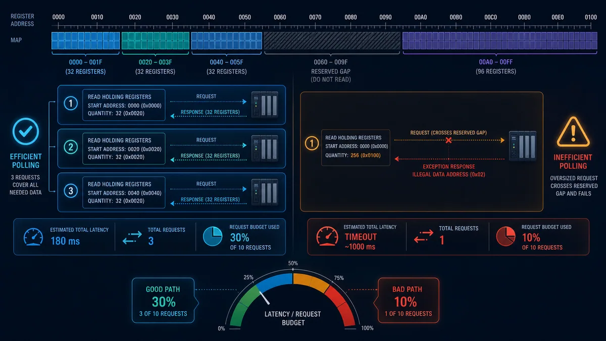
The PDU's 16-bit address space does not mean every server implements 65,536 elements or that one request can read the whole space. Function-specific maximum quantities and the server's implemented ranges apply. A request can start on a valid item and still fail because its quantity crosses an unimplemented/reserved gap or exceeds a device limit.
Respect value width and alignment
If a 32-bit value begins at holding offset 100, it consumes offsets 100 and 101. The next nonoverlapping 32-bit item starts at 102. A 64-bit value consumes four consecutive registers. Some devices require even start offsets for multi-register types; others do not. Record and validate the published start and width rather than imposing a universal alignment rule.
| Type | Common register width | Starting offset example | Occupied offsets | Next free offset |
|---|---|---|---|---|
| 16-bit status | 1 | 20 | 20 | 21 |
| 32-bit counter | 2 | 21 | 21–22 | 23 |
| 32-bit float | 2 | 23 | 23–24 | 25 |
| 64-bit total | 4 | 25 | 25–28 | 29 |
| 8-character ASCII packed two per register | 4 | 29 | 29–32 | 33 |
Live mini-lab
Try it: press START, then STOP
A stop-dominant seal-in rung: START latches the motor output through its own contact, and STOP breaks the circuit.
Watch the output lamp: it stays on after START until you press STOP.
Free to start · runs in your browserOpens plcsimulationsoftware.com — same team
Decode 16-, 32- and 64-bit values
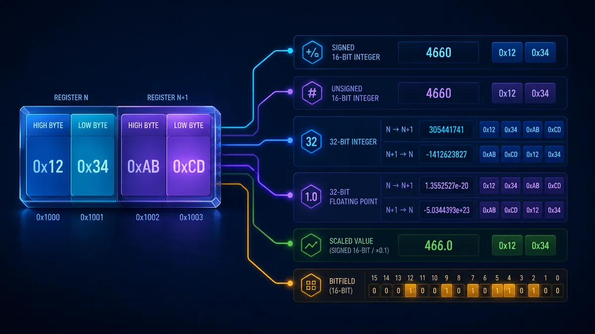
A 16-bit register is only a bit pattern. The map determines whether it represents unsigned 0…65535, signed two's-complement −32768…32767, a status bitfield, a binary-coded value, two packed bytes or a scaled engineering quantity.
Start with raw hexadecimal words
| Raw word | Unsigned view | Signed two's-complement view | Possible mapped meaning |
|---|---|---|---|
0x0000 |
0 | 0 | zero, false bits or no alarm—unless quality says invalid |
0x0001 |
1 | 1 | state code 1 or bit 0 set |
0x7FFF |
32767 | 32767 | upper signed positive value |
0x8000 |
32768 | −32768 | sign boundary or bit 15 flag |
0xFFFF |
65535 | −1 | negative one, all flags set, sentinel or invalid code |
Do not treat 0xFFFF as invalid universally. It can be a legitimate signed −1, an unsigned maximum, a bitmask or a manufacturer-defined sentinel. The map and quality/status define meaning.
Understand byte order versus word order
For the 16-bit register value 0x1234, Modbus represents the high-order byte 0x12 before low-order byte 0x34 in the register data. For a 32-bit application value spanning two registers, however, the device decides which 16-bit word is at the lower register address. Common tool labels include big-endian, little-endian, word swap, byte swap, ABCD, CDAB, BADC and DCBA; vendors use these labels inconsistently.
| Registers read in address order | Byte sequence label | Typical tool wording | Requirement |
|---|---|---|---|
0x1234, 0xABCD |
12 34 AB CD / ABCD |
high word first / no word swap | verify against device map/test pattern |
0xABCD, 0x1234 |
AB CD 12 34 / CDAB relative to intended pattern |
low word first / word swap | verify against device map/test pattern |
| bytes swapped within each word | BADC or DCBA patterns | byte swap, sometimes combined word/byte swap | only use if endpoint/tool really implements it |
Use a distinctive four-byte test pattern, not zero or 1 alone. A value whose high and low words are equal cannot reveal word order. When a real device cannot be safely forced to the pattern, compare several known stable engineering points and raw words from the manufacturer's diagnostic tool.
Apply scaling exactly once
Scaled integers preserve deterministic resolution without requiring a floating-point representation. If the map states “signed 16-bit, 0.1 °C,” raw 253 means 25.3 °C. If the map states “value × 10,” confirm whether that describes the raw-to-engineering or engineering-to-register direction—wording varies.
| Map expression | Raw-to-engineering calculation | Example |
|---|---|---|
resolution 0.1 unit/count |
engineering = raw × 0.1 | 253 → 25.3 |
scale 10 counts/unit |
engineering = raw ÷ 10 | 253 → 25.3 |
| affine range | engineering = raw × slope + offset | product-specific |
| percentage in 0–10000 | percent = raw ÷ 100 | 7550 → 75.50% |
Preserve raw value and derived engineering value during commissioning. If the raw word matches but engineering value does not, the fault is type/scale. If the raw word is wrong, investigate address, word order, server mapping or process source.
Treat bitfields, strings and time values explicitly
Bitfields often pack alarms, states or command flags into a holding register. The least significant bit is conventionally bit 0, but diagrams may number visible bits 1–16. Record hexadecimal mask and semantic name to remove ambiguity.
Bitfield mapping example
| Semantic flag | Bit index | Hex mask | Access/ownership | Validation |
|---|---|---|---|---|
| ready | 0 | 0x0001 |
server status read-only in application | set/clear through controlled device state |
| running | 1 | 0x0002 |
server status | compare physical/process feedback |
| warning | 4 | 0x0010 |
server status | inject approved warning condition |
| fault | 7 | 0x0080 |
server status | preserve fault code before reset |
| command reset | 8 | 0x0100 |
client request; server validates | one acknowledged transaction, not maintained blindly |
Writing a whole status/command word from multiple clients creates read-modify-write races. Give one side ownership or use a supported mask-write/transaction protocol with clear semantics. Standard Modbus access does not provide multi-client application locking.
Text can store two characters per register, one character per register or vendor-specific encodings and termination. Date/time may be Unix seconds, BCD fields, separate registers or a vendor structure. A 64-bit counter may roll, latch or require a snapshot mechanism to avoid reading different halves during an update. The register map must define these behaviors; the data type name alone is insufficient.
Build a controlled register-map contract
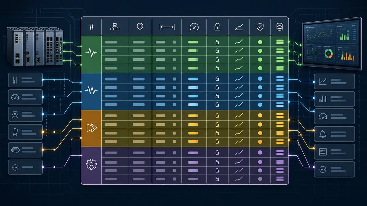
A good map lets another engineer reproduce the interface without opening either project's tag editor. It should be versioned, machine-readable where practical and generated/validated for duplicates and overlaps.
Required register-map fields
| Contract field | Purpose | Example form |
|---|---|---|
| stable ID/name | semantic join key | PUMP01_SPEED_PV |
| logical block/function | selects Modbus table/access | holding register / FC03 |
| PDU offset | exact zero-based wire start | decimal 120, hex 0x0078 |
| reference notation | human/vendor documentation | 40121 if convention is confirmed |
| client syntax | exact entry for each driver | product-specific string/table + address |
| register width | prevents overlap/truncated reads | 2 registers |
| raw type/order | signed/unsigned/float/bitfield/text and word/byte order | IEEE-754 float, high word first |
| scale/unit/range | engineering meaning and validation | rpm, 0–1800, 1 rpm/count |
| access/owner | read-only/request/configuration and validating side | HMI reads; PLC publishes |
| update/quality | polling class, heartbeat/data age and invalid handling | normal group, stale after approved threshold |
| lifecycle | introduced/deprecated version and compatibility | interface v2.3 |
| source/test | originating variable/document and acceptance case | PLC tag + MAP-042 |
Partition the address space by purpose
One maintainable pattern reserves contiguous regions for identity/interface version, status, measurements, commands, setpoints, alarms, configuration and diagnostics. The exact offsets are your interface design; avoid copying a public example into production.
| Region | Design rule | Why |
|---|---|---|
| identity/version | fixed read-only words at known start | client can reject incompatible map before interpreting data |
| status/measurements | server-owned read data, grouped by update need | efficient read blocks and clear ownership |
| command requests | client-owned request words with sequence/ack | avoids fleeting pulses and ambiguous replay |
| setpoints | requested, accepted and active values separated | shows validation and current process authority |
| alarm/status bits | read-only bitfields plus codes/timestamps as required | extractable diagnostics without uncontrolled writes |
| configuration | role-restricted and change-controlled, often separate polling | avoids routine display client writing parameters |
| diagnostics | heartbeat, quality, counters and last result | makes stale/partial failure visible |
| reserved growth | documented gaps that client does not poll unless implemented | version growth without remapping every field |
Do not expose arbitrary PLC memory merely because an MB_SERVER block can point at a data buffer. Create a stable interface layer that copies/validates application data. This decouples PLC variable layout from external compatibility and prevents clients from writing implementation state.
Handle overlapping maps and aliases deliberately
The Modbus specification allows four logical blocks to be bound to device application memory independently or overlap. CODESYS documents implementations in which coils/discrete and holding/input data can map onto common I/O data. A device may therefore expose one physical value through FC03 and FC04, or bits through both coil and register views.
Alias policy
| Alias case | Benefit | Risk | Control |
|---|---|---|---|
| same measurement in FC03 and FC04 | compatibility with clients | clients disagree about authoritative access | document canonical function and identical-value test |
| status word plus coil aliases | convenient bit client access | bit order/memory overlap ambiguity | publish masks/offsets and prohibit writes to aliases |
| input/output process image overlap | compact implementation | direction described from host/server perspective can confuse client | document wire perspective and access rights |
| configuration exposed at multiple bases | legacy compatibility | writes to old/new alias may diverge | version/deprecation and one internal owner |
Never infer that because two functions return identical data today they are contractual aliases. Confirm in the manufacturer documentation and include both in regression tests if clients depend on them.
Design efficient polling blocks
Polling should group contiguous values with the same table, compatible update need and supported range. A single giant read can cross reserved holes, exceed function/device quantity limits, delay critical data and make one bad address fail the whole group. One request per tag wastes bandwidth and server processing.
Create blocks from valid contiguous ranges
| Block design question | Good evidence |
|---|---|
| are all elements in the same logical table/function? | FC/table column identical |
| does the block cover whole multi-register values? | start/last offset generated from each width |
| are every address and gap implemented? | device/server map and boundary probe |
| is quantity within protocol and device/client limit? | exact function manual and successful max test |
| do values need the same update rate? | operator/process requirement and data-age budget |
| can a write block be applied coherently? | device commit/sequence behavior and partial-failure plan |
| does another client modify the same area? | ownership matrix and concurrency test |
| what happens on timeout/exception? | quality, retry/backoff and stale-display rule |
Use fast, normal, slow and on-demand groups. Identity/configuration can be read at startup or infrequently; critical operator feedback may need a faster bounded group. Measure round-trip distribution and server load rather than assuming that fewer requests always means lower latency.
Commission addressing with known patterns
Simulation and a diagnostic client can prove notation and representation before HMI/SCADA complexity is added. Start with one known 16-bit word, then a two-register pattern, then signed/scaled and writable cases.
Addressing proof sequence

| Gate | Test | Expected evidence |
|---|---|---|
| endpoint/table | connect to exact server and request intended function | valid response or exact exception from intended device |
| base translation | place/read a distinctive word at server offset 0 and adjacent offset | client entry maps to exact zero-based PDU start in trace |
| boundaries | read first/last implemented item and one outside | valid range succeeds; invalid request returns documented exception |
| quantity | test one, normal block and supported maximum | response byte count/data length and performance agree |
| signedness | publish safe 1, −1 and boundary patterns |
raw word constant; signed interpretation correct |
| width/order | publish distinctive two-/four-register patterns | client reconstructs exact 32-/64-bit value |
| scaling | publish known raw points across range | engineering conversion and unit correct exactly once |
| bitfields | set one defined bit at a time | mask and bit index agree without neighboring changes |
| access | read and attempt approved/prohibited writes | permission and PLC validation behave as contract |
| coherence | update multi-register value while polling | snapshot/sequence method prevents mixed halves if required |
| quality | interrupt requests or freeze heartbeat | value becomes stale/bad visibly, not plausible live data |
| regression | export raw capture/results against interface version | repeatable test package for future firmware/client changes |
Use the Modbus simulator to create controlled register values and faults, compare client address entry with the actual request, and test word order/scaling without touching a process. A simulator proves protocol and application mapping; repeat the applicable cases with the installed endpoint.
For end-to-end HMI commands, polling and stale-data behavior, see Modbus PLC–HMI communication.
Troubleshoot register values by symptom
Symptom-to-evidence matrix
| Symptom | First discriminating evidence | Likely cause | Avoid |
|---|---|---|---|
| every value shifted by one | packet start offset versus known server offset | zero/one-base translation | adding one in several layers |
| correct address, exception 02 | function, full requested range and implemented gaps | wrong table or unimplemented/cross-gap quantity | calling all exceptions timeouts |
| FC03 works, FC04 fails | device map's logical block | value exists only as holding register | assuming “input value” means input-register table |
| 16-bit words correct, 32-bit wrong | two raw words in address order | word order/type/start offset | changing scale first |
| positive values work, negative huge | raw word and signed/unsigned client type | unsigned interpretation of signed two's-complement | modifying PLC value |
| value off by factor 10/100 | raw word and map scale direction | scaling applied twice/missing | arbitrary decimal adjustment without raw proof |
| bits reversed | raw hex word and published masks | bit index/byte interpretation | reversing all bytes for one bitfield |
| text characters swapped | raw words/bytes and encoding definition | per-register character order/termination | treating string like float word order |
| intermittent impossible 32-bit value | consecutive raw reads and update sequence | torn read across server update | replacing network cable first |
| large read fails, small reads work | failing block boundaries and server quantity limit | reserved gap/limit | assuming fewer requests is always worse |
| write acknowledges but process unchanged | server raw map, access and application accepted/active value | request area requires validation/commit or write ignored by state | bypassing PLC interlocks |
| values remain after disconnect | request quality, heartbeat and last-success age | client displays last good/stale cache | treating plausible value as live |
Diagnostic answer map for search and AI-assisted mapping
| User or AI query | Concise answer | Required qualification |
|---|---|---|
| Is Modbus address 40001 sent on the wire? | No. FC03 selects holding registers and the PDU carries zero-based offset 0 for the first element. | A client may accept 40001 and translate it internally. |
| What is the difference between register 1 and 40001? | Both may describe the first holding register under different tool/document conventions. | Confirm logical table and zero/one base; 1 could also be raw offset 1. |
| Are Modbus registers zero-based or one-based? | The PDU address is zero-based; data-model elements and common references are one-based. | Engineering tools can expose either convention. |
| What is a holding register? | A 16-bit Modbus data element read with FC03 and writable through supported holding-register functions. | A real device can make individual locations read-only or unimplemented. |
| How many bytes are in a Modbus register? | Two bytes, or 16 bits. | A 32-bit value needs two registers and device-specific word order. |
| What does 4x mean in Modbus? | It denotes the holding-register logical block in legacy human notation. | The prefix is not transmitted in the PDU. |
| How do I convert 40100 to an offset? | Under classic one-based holding notation, subtract 40001: offset 99 (0x0063). |
First verify the manual really uses that convention. |
| Why is my Modbus float wrong? | The endpoints likely disagree on starting offset, two-register word order or IEEE-754 type. | Compare raw words with a distinctive known value before changing scale. |
| Can coils and holding registers overlap? | The specification permits device application mappings that overlap. | Only rely on aliases documented by the endpoint manufacturer. |
| How should I group Modbus reads? | Use contiguous implemented ranges with complete values, compatible update rates and supported quantities. | Split around reserved gaps and measure server/client performance. |
| How do I create a Modbus register mapping? | Record source variable, table/function, PDU offset, displayed reference, width/type/order, scale/units, access, quality and a known-value test. | Keep endpoint manual, client convention and interface revision with the map. |
Frequently asked questions
What are the four types of Modbus addresses?
Coils are one-bit read/write data, discrete inputs are one-bit read-only data, input registers are 16-bit read-only data, and holding registers are 16-bit read/write data in the protocol model. Function codes select which block a request addresses.
Why do some Modbus programs start at address 0 and others at 1?
The protocol frame uses a zero-based PDU offset, while human data-model numbering commonly starts at one. Client software may expose either representation or translate a 4xxxx reference. Configure from that tool's manual and verify the actual request.
Is holding register 40001 offset 0 or 1?
In classic one-based reference notation, 40001 corresponds to PDU holding-register offset 0. But a column labeled simply Register 1 could mean one-based element 1 or raw offset 1. Confirm the endpoint and client conventions.
What is the Modbus address range?
The PDU starting-address field is a zero-based 16-bit value from 0 through 65535 inside the logical block selected by the function code. A server usually implements only a subset, and the full requested span—not only its first address—must be valid for that function and firmware map.
How are 32-bit floats stored in Modbus registers?
They occupy two 16-bit registers when an endpoint uses IEEE-754 single precision. The order of those two words is device-specific, and some tools also offer byte swapping. Read raw words for a known value and set the client's exact order.
What is Modbus word swap?
Word swap reverses the order of the 16-bit words used to construct a multi-register value. It is different from swapping bytes within each register. Tool labels vary, so compare a distinctive raw four-byte pattern rather than relying on the label.
What is the Modbus holding-register address range?
Holding-register PDU offsets can theoretically run from 0 through 65535; this is 65,536 possible elements in the function-selected block. Classic 40001…49999 notation displays only a smaller legacy range, while some tools use extended six-digit references or a table plus offset. The installed server map defines which locations actually exist.
Can I write several Modbus registers at once?
FC16 writes multiple contiguous holding registers when the server supports the range and access. Whether the device applies the block atomically or requires a commit/sequence is product-specific. Do not assume protocol acknowledgement means the process accepted every parameter.
Why does a large Modbus read return illegal data address?
The requested range may cross a reserved/unimplemented location or exceed a server/function quantity limit even though the first address is valid. Calculate the last offset, inspect every gap and split the block along implemented boundaries.
What should a Modbus register map include?
A Modbus register mapping should include function/table, zero-based offset, human reference, width, type, word/byte order, scale, units, range, access/owner, quality/update behavior, interface version, source variable and a repeatable test case.
Sources, review scope, and limitations
This guide was reviewed on August 28, 2026 against the Modbus application specification and current public implementation documentation. Driver notation, vendor maps, access, word order, aliases and limits change by endpoint, firmware and tool version. Retain the exact register-map and client configuration revisions used in acceptance testing.
- Modbus Application Protocol Specification V1.1b3 — Modbus Organization
- Modbus specifications and implementation guides — Modbus Organization
- Introduction to Modbus, functions and relative addressing — Modbus Organization
- Modbus TCP Toolkit and diagnostic resources — Modbus Organization
- S7-1200/S7-1500 Communication Function Manual, MB_CLIENT/MB_SERVER — Siemens
- Modbus server-channel offsets and register access — CODESYS
- Modbus serial device data areas and mapping — CODESYS
- TM3 bus-coupler Modbus register mapping and diagnostic areas — Schneider Electric
- PowerLogic PM8000 Modbus implementation and register behavior — Schneider Electric
- EasyBuilder Pro Modbus Gateway address mapping — Weintek
- NIST SP 800-82 Rev. 3, Guide to Operational Technology Security
The images are conceptual and do not define an endpoint register map, request limits, word order, access rights or process commands. This page does not authorize writes to production equipment, bypass interlocks or treat standard Modbus as authenticated safety communication. Only qualified, authorized personnel following the endpoint manuals, site change/access controls, process-risk requirements and approved test procedure should configure or write industrial Modbus data.
Now run it · free to start
Learn Modbus, then the networks around it
Modbus first because it is simple and everywhere, then the Ethernet-based protocols and the SCADA layer above them. Free to start.
Ownership disclosure: PLC Programming IO and PLC Simulation Software are operated by the same publisher.
PLC Programming IO Editorial Team
Industrial automation education, references, and software testing
The PLC Programming IO Editorial Team publishes sourced industrial-automation education and documents how material is reviewed, tested, and corrected. A team byline means the publisher is responsible for the page; it does not represent a fictional person or imply an engineering licence.
Coverage:
- • PLC programming concepts and examples
- • Vendor software tutorials and comparisons
- • SCADA, HMI, protocols, and instrumentation
- • Training, careers, and reference material
Review standard:
- • Prefer primary and official sources
- • Record software versions when material
- • Separate tested facts from estimates
- • Publish material corrections
Important scope note
This site provides education, not project-specific engineering approval. Safety, code, and compliance decisions require a qualified person with access to the actual machine and jurisdiction.