HMI Modbus TCP and PLC–HMI Communication
Design and commission reliable Modbus communication between a PLC and HMI with explicit roles, register contracts, command handshakes, polling budgets, stale-data behavior and test evidence.
Review status: Editorially reviewed against cited Modbus Organization, Siemens, Schneider Electric, CODESYS and Weintek documentation; exact addressing, limits, timing, access and safe-state behavior require installed-product verification
Direct answer
For an HMI Modbus TCP connection, first assign explicit roles: the HMI commonly acts as the client that initiates reads and writes, while the PLC acts as the server exposing coils and registers. Configure the server IP address, TCP port, driver and any required Unit Identifier before mapping a single known test tag. For Modbus RTU, prove the serial parameters and physical link instead. In either case, create a controlled tag/register contract that defines the table, protocol address, data type, byte/word order, engineering scale, read/write authority, update class and safe behavior for every HMI tag.
Do not connect screen buttons directly to fleeting PLC bits and assume the operator command was received. For consequential commands, exchange a retained request with a transaction or sequence value and have PLC logic return accepted, done or rejected status. Group display reads into sensible contiguous blocks, keep fast and slow polling classes separate, measure the real request/response budget, and expose communication quality, heartbeat, last-success time and data age. When updates stop, the HMI should mark values stale rather than showing the last good number as if it were live.
Commission the interface in layers: prove IP or serial reachability, prove one known raw value, verify table and zero/one-based addressing, test each data representation, confirm reads and writes separately, test every command outcome, inject loss and recovery, and finally validate the process behavior under an authorized site procedure. A successful Modbus read proves data exchange only; it does not prove that a command is safe, permitted or correctly interlocked.

Define the PLC–HMI architecture
Modbus is an application protocol built around client requests and server responses. The client asks to read or write a specific data model location; the server returns data, acknowledges the write or returns an exception. The terms client/server are current Modbus terminology. Some products and older manuals still say master/slave.
Assign one initiating role deliberately
For a conventional operator panel, the HMI is usually the client because it decides which tags to poll for the active screens and when to send operator writes. The PLC is usually the server because it owns the process state and exposes a deliberately mapped interface. This is a common pattern, not an unbreakable protocol rule: PLCs can be clients, HMIs can provide server/gateway functions, and a PLC can run client and server services at the same time if the product supports them.
| Architecture decision | Common PLC–HMI choice | Evidence to record | Failure if assumed |
|---|---|---|---|
| request initiator | HMI as Modbus client | driver/channel and connection configuration | two servers wait forever or two clients target nothing |
| data owner | PLC as Modbus server | published memory/data area and access rules | HMI writes an implementation address with no stable contract |
| transport | TCP, RTU or supported gateway route | physical interface, protocol, port/serial parameters | link indicators exist but frames are incompatible |
| endpoint identity | IP address for TCP; node address for RTU | as-built network schedule | requests reach the wrong controller/device |
| gateway routing | Modbus TCP Unit Identifier mapped to serial/server node | gateway map and exception behavior | TCP connection succeeds but downstream node never answers |
| concurrent clients | HMI plus SCADA, historian or engineering client | documented connection/request limits and load test | intermittent refusal, delay or starvation under real load |
| write authority | restricted setpoints/commands only | per-tag permissions and PLC validation | display client can alter uncontrolled process memory |
Schneider documents an HMI SCU Modbus server that maps defined input and output register areas, supports up to ten client connections, and processes one request per client connection in a controller cycle. CODESYS documents a separate server implementation with up to sixteen parallel client connections. Those values illustrate why capacity is a product/implementation limit, not a property guaranteed by the Modbus protocol. Verify the exact PLC runtime, firmware and task behavior.
Configure HMI Modbus TCP, RTU or a controlled gateway
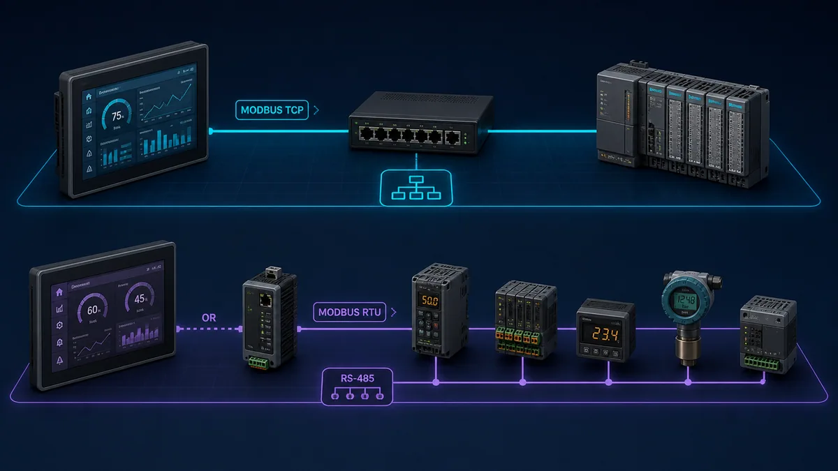
| Item | Modbus TCP | Modbus RTU | TCP-to-RTU gateway consequence |
|---|---|---|---|
| physical/network layer | Ethernet and IP network | serial line, commonly RS-485 | both sides must be engineered and diagnosed |
| endpoint | server IP/hostname and TCP port; default registered port is 502 | unique server address on the serial segment | TCP Unit Identifier or gateway mapping selects downstream node |
| framing | MBAP header with transaction identifier; no RTU CRC field | binary frame with CRC and silent timing boundaries | gateway translates framing and schedules the serial bus |
| concurrency | TCP connections/requests depend on implementation | one client controls request sequence on a segment | several TCP clients can overload one serial queue |
| primary timing constraint | server processing, network, socket/connection and client polling | baud rate, bytes per request, turnaround and inter-frame timing | client timeout must cover gateway queue plus serial response |
| duplicate identity risk | duplicate IP or wrong network route | duplicate node address | wrong unit mapping can make a healthy TCP socket misleading |
| diagnostic split | switch/port, TCP session, Modbus request/response | line wiring/bias/termination, serial settings, address, CRC | capture/log evidence on both sides of translation |
Siemens WinCC documentation for Standard Modbus TCP/IP identifies the server address, port 502 and remote server/slave address used when a bridge is present. It notes default remote values when no bridge is used. Follow the selected HMI driver's documentation: do not copy another vendor's unit value or address syntax without checking.
For serial physical-layer design and diagnosis, use the RS-485 wiring guide. The HMI tag contract described here begins after the cable, termination, biasing, reference and serial parameters are proven.
Create a versioned Modbus tag/register contract
The register contract is the single source of truth between PLC and HMI teams. It should be generated or reviewed from controlled PLC variables, not reverse-engineered from screen objects after commissioning. Give it an interface version and change history. A spreadsheet is useful, but a machine-readable export with validation is stronger because duplicate addresses, overlaps and type-width mistakes can be detected automatically.
Record enough information to reproduce every tag
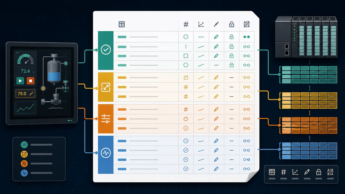
| Contract field | Example form | Why it matters |
|---|---|---|
| stable tag ID | MIXER_01_SPEED_PV |
human-readable join key that survives screen rearrangement |
| process meaning/unit | actual mixer speed, rpm | prevents a correct raw value receiving the wrong label |
| table and protocol offset | holding register, offset 120 | separates wire address from 4xxxx display notation |
| HMI driver address | exact syntax used in that driver | documents zero/one-base translation instead of relying on memory |
| function/access | read with FC03; write through approved command block | prevents a read-only/status value becoming writable by convention |
| raw representation | unsigned/signed 16-bit; 32-bit integer; IEEE-754; bits | determines width, signedness and decoding |
| byte/word order | high/low word order per endpoint pair | required for multi-register values; do not call every variation “endianness” |
| scaling/limits | raw × 0.1 rpm; valid 0–1800 | makes engineering conversion and range checking explicit |
| quality/freshness | group heartbeat, update class and maximum age | prevents last-good data being presented as live |
| ownership | PLC publishes; HMI requests; PLC validates | resolves which side may modify the value |
| alarm/display behavior | bad quality, out-of-range and stale treatment | defines operator-visible failure rather than only protocol success |
| version/test ID | interface v3.2, case TAG-017 |
ties acceptance evidence to an exact contract revision |
Separate protocol offset from human register notation
The Modbus Protocol Data Unit carries a zero-based starting address from 0 to 65535; it does not transmit a 40001 label. Documentation and HMI drivers may show the first holding register as 40001, 400001, 4x:1, HR1 or offset 0. These can refer to the same underlying item—or not—depending on the driver convention. Record all three of: data table, zero-based protocol offset and exact HMI driver string.
| Intended item | Protocol PDU offset | Possible human notation | Verification method |
|---|---|---|---|
| first holding register | 0 | 40001, 400001 or driver-specific HR0/HR1 |
place a distinctive test word and read one address only |
| holding register at offset 99 | 99 | often 40100, but driver syntax varies |
compare driver diagnostic request and server map |
| first input register | 0 | often 30001 |
confirm FC04 rather than assuming a 3 prefix selects it |
| first coil | 0 | often 00001 |
verify FC01/FC05/FC15 capability and PLC mapping |
| first discrete input | 0 | often 10001 |
verify FC02 and read-only behavior |
Keep the page-specific addressing depth here limited to integration practice. For function and exception diagnosis, use the Modbus function and exception code guide; the protocol's legal address and quantity are not proof that the installed server implements them.
Map data types, scaling and access correctly
A Modbus register is 16 bits. The protocol defines the bytes within a 16-bit register, but product implementations decide how larger values are distributed across multiple registers. A 32-bit floating-point tag therefore needs two valid consecutive registers, compatible word order and the same interpretation at both endpoints.
Prove raw values before engineering values
| Data shape | Register footprint | Test pattern | Common failure |
|---|---|---|---|
| Boolean coil | one coil | alternate one known bit while neighboring bits remain fixed | wrong table, packed-bit index or write permission |
| 16-bit unsigned | one register | 1, 255, 256, upper-range safe value |
one-address shift or signed interpretation |
| 16-bit signed | one register | 1, -1, safe negative engineering point |
HMI displays 65535 for -1 |
| 32-bit integer | two registers | distinctive bytes/words and safe positive/negative values | swapped register order or half-value overlap |
| IEEE-754 float | two registers | several exact/known values, including a fraction | incompatible float/word order or wrong starting address |
| scaled integer | one or two registers | raw value plus independent engineering conversion | scaling applied twice or on neither side |
| bitfield/status word | one register | set one defined bit at a time | bit numbering reversed or reserved bits treated as commands |
| text | multiple registers | short controlled ASCII pattern and odd/even length | byte order, termination, encoding or width mismatch |
Start diagnosis in a server/client monitor that can show the raw 16-bit words and request details. If raw words match the contract but the HMI value is wrong, investigate the HMI data type, word order and scaling. If raw words are already wrong, move toward the PLC mapping, server data area or address/function selection.
Keep status, setpoint and command ownership separate
Do not make the operator's numeric entry object write the same register that the PLC uses for actual process feedback. Publish distinct values such as requested setpoint, active/validated setpoint and measured process value. The PLC should validate authority, operating state, range, rate of change and interlocks before accepting a request. Where the HMI supports limits, use them as usability controls—not as the only protection.
| Interface class | HMI behavior | PLC behavior | On communication loss |
|---|---|---|---|
| measurement/status | read and display with quality/age | publish authoritative state | mark stale/unknown; do not silently force plausible live value |
| operator setpoint request | write candidate with confirmation where risk requires | range/state/authority validation; publish accepted value/result | leave process under PLC policy; show uncertain request status |
| command request | retained handshake, sequence and operator feedback | accept/reject once, execute through application state machine | never infer success from button release or reconnect |
| mode/permission | request only when UI authorization allows | enforce final authorization and interlocks | default to defined PLC control policy |
| recipe/batch data | versioned block with checksum/commit where appropriate | validate coherent dataset before applying | reject partial/uncommitted transfer |
| diagnostic/configuration | role-restricted, logged and clearly separated | enforce product/site controls | disable or restrict according to security design |
Modbus itself does not provide modern authentication or role-based authorization. Segment the control network, restrict allowed paths and services, use device capabilities and secure remote-access controls, and enforce consequential command validity in PLC logic. A hidden HMI button is not an access-control boundary.
Live mini-lab
Try it: press START, then STOP
A stop-dominant seal-in rung: START latches the motor output through its own contact, and STOP breaks the circuit.
Watch the output lamp: it stays on after START until you press STOP.
Free to start · runs in your browserOpens plcsimulationsoftware.com — same team
Design commands as acknowledged transactions
A momentary HMI button can turn a request bit on and off between polls, during a disconnect, or before the PLC task consumes it. A simple maintained bit avoids some pulse loss but creates new ambiguity: after reconnection, is the old 1 a new command, an already executed command or a stale state? A handshake resolves the uncertainty.
Use request, acceptance and completion states
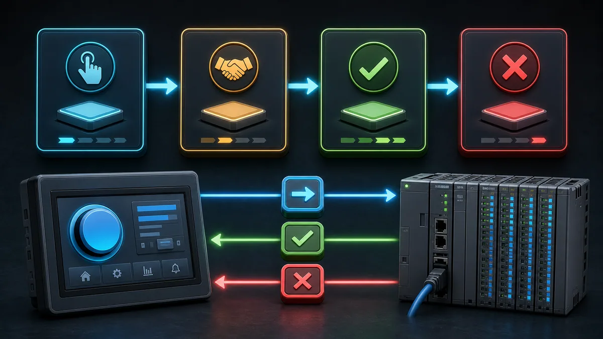
One general pattern uses CommandCode, CommandSequence, optional parameters and RequestValid. The PLC copies the sequence into AcceptedSequence only when it recognizes and accepts that exact request. It then publishes a state such as idle, pending, executing, done or rejected plus a result/reason code. The HMI clears or advances its request only after seeing the matching sequence. Exact fields depend on risk and product constraints; a toggle bit or incrementing sequence is often enough for a simple non-safety action.
| Phase | HMI responsibility | PLC responsibility | Operator-visible result |
|---|---|---|---|
| compose | write complete parameters and new sequence before valid flag/commit | ignore incomplete or duplicate requests | confirmation or pending indicator |
| receive | retain request until matching acknowledgement or defined timeout | capture coherent request and sequence | “sent, awaiting controller” rather than immediate success |
| validate | do not decide final process permissibility | check mode, state, authority, range and interlocks | accepted or rejected with actionable reason |
| execute | monitor matching transaction | run application state machine; avoid blocking communication task | executing/progress if meaningful |
| complete | close transaction only on matching terminal state | latch done/failed result long enough for client to observe | success/failure tied to the requested action |
| recover | on reconnect, compare sequence and controller state | do not execute a previously handled duplicate | uncertain/in-progress state reconciled before retry |
For an emergency stop, guard opening or other safety function, this ordinary HMI/Modbus handshake is not the safety function. Use the validated safety architecture and product-specific safety communication. The HMI may display safety status, but display and standard PLC logic do not replace independent risk controls.
Avoid read-modify-write collisions
If HMI and PLC both write different bits inside the same holding register, one side can overwrite the other's newer value. Multiple clients can do the same. Give each writable item a clear owner; group HMI request bits in a dedicated area the PLC reads but does not casually rewrite; return separate PLC status words. If the device supports mask-write or atomic operations, confirm the entire endpoint chain implements them before relying on that behavior.
Engineer polling, timeouts and PLC load
Polling every tag at the fastest selectable rate is not a performance strategy. Each HMI connection has request overhead, server processing, scheduling and response time. Modbus can read consecutive coils/registers in one request, but large unrelated blocks can waste bandwidth and make one invalid gap break the whole group.
Build update classes around operator need
| Update class | Typical content | Design principle | Acceptance evidence |
|---|---|---|---|
| fast operator feedback | running state, key feedback for active manual action | only values whose delay changes safe/usable operation | measured end-to-end update under worst planned load |
| normal process display | pressures, levels, speeds and statuses | contiguous blocks at a human-usable cadence | screen update stable without request errors |
| slow condition | temperatures, totals, maintenance counters | do not consume fast cycle without a real need | age remains within documented display requirement |
| event/on-demand | recipe detail, diagnostics, inactive popup | poll when screen/function is active if HMI behavior is known | entering screen does not create timeout burst |
| heartbeat/quality | controller life counter, mode, interface version | independent enough to detect a frozen value group | loss/restart/reconnect cases produce explicit state |
| command response | accepted sequence and result | fast enough for operator feedback but not assumed instantaneous | request cannot be lost, duplicated or falsely confirmed |
Estimate a request budget rather than only configuring a poll interval. For each connection, list groups, requested quantities and repetition times. Measure actual round-trip distribution, server task load, TCP connection count, exceptions and missed/late updates with all planned HMI screens, SCADA clients and engineering tools active. On RTU, include baud rate, request and response lengths, turnaround, inter-frame timing, retries and every node in the schedule.
Separate response timeout from data freshness
A response timeout says one request did not complete within its allowed time. Data freshness says how old the last validated value is. They are related but not equivalent: a single request can time out while a value remains within its allowable age, or requests can keep succeeding while a PLC application variable is frozen.
CODESYS documents a client response timeout and automatic reconnect option. Schneider documents a configurable health timeout and repetition rate for an I/O scanner, with a health bit changing when the timeout expires. Siemens warns in its WinCC Modicon Modbus TCP/IP documentation that TCP connection breakdown may not be detected immediately and may go undetected if no tags are requested, recommending coordination/area-pointer behavior for that product. These examples support one rule: define application-level quality and heartbeat evidence rather than equating an open socket with healthy live process data.
Make stale data unmistakable
The worst display failure is often a believable old number. Retaining a last good value can help an operator understand what was happening before loss, but only if the UI visibly distinguishes that historical value from a live measurement and shows its age.
Publish heartbeat, quality and age
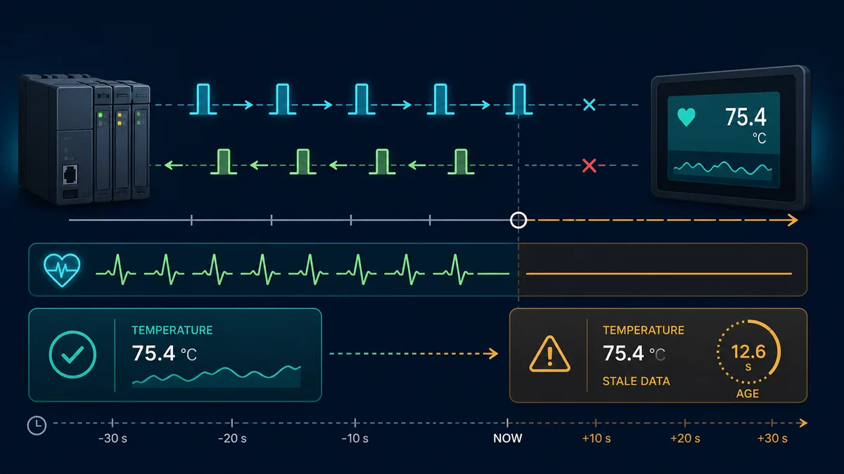
| Signal | What it proves | What it does not prove | HMI treatment |
|---|---|---|---|
| Ethernet link | local physical link is present | route, TCP, Modbus server or PLC application health | diagnostic only; never “PLC healthy” by itself |
| TCP connected | socket/session is established | current requests or changing process data | show connection state separately from quality |
| last request success | one Modbus request returned validly | every tag group or PLC scan is healthy | per-connection/group quality input |
| heartbeat counter | publishing PLC logic is executing and value reaches HMI | all field I/O/process logic is correct | alarm if counter does not change within approved window |
| interface version | HMI and PLC contract versions agree | every individual mapping is correct | block or warn on incompatible versions |
| data timestamp/age | elapsed time since validated update | physical measurement itself is accurate | display stale badge and age; inhibit uncertain commands as designed |
| PLC mode/diagnostic | controller-reported run/fault state | communication path is independent or safety-rated | display with source/quality qualification |
A robust display can retain the last numeric value in muted styling, overlay “stale,” show age or last update, alarm once according to alarm philosophy and disable commands that cannot be safely issued without current state. Avoid replacing every lost value with zero: zero may be a plausible and dangerous process reading. Also avoid flashing the entire screen continuously; use a consistent quality language that operators can recognize under pressure.
Design reconnect behavior explicitly
On reconnect, read interface version, heartbeat, PLC mode, command sequences and authoritative states before re-enabling writes. Do not automatically replay every queued operator action. Pending commands need a product-specific reconciliation rule: discover whether the matching sequence was accepted or completed, then let the operator retry only when the result is known or the procedure explicitly permits it.
Configure the HMI and PLC in a controlled sequence
Configuration order matters because it provides one known reference before hundreds of tags obscure the cause.
PLC/server checklist
- Confirm the exact PLC CPU/runtime, firmware, interface and license support the required Modbus server role and functions.
- Allocate a bounded, documented data area rather than exposing arbitrary application memory.
- Map status and measurements from application logic into that interface, and HMI requests from the interface into validation logic.
- Define read-only, writable and unsupported ranges; confirm behavior for illegal functions, addresses, quantities and values.
- Add interface version, application heartbeat, controller/machine state, command acknowledgement and diagnostic counters.
- Configure endpoint address, port or serial parameters, unit/node identity, connection/client limit, timeout/watchdog and restart behavior from the exact product manual.
- Prove safe response to client loss, stale requests, PLC STOP/restart and partial initialization under the site's authorized procedure.
HMI/client checklist
- Select the driver that matches the PLC/server implementation and transport—not merely a driver whose name includes Modbus.
- Configure server IP and port for TCP, or baud, parity, data/stop bits and node for RTU; add unit identifier only as the driver/gateway design requires.
- Create one test tag at a known protocol offset and compare the raw request/response before importing the full tag set.
- Configure table/function, exact driver address, type, word order, scale, limits, update class, read/write permission and quality behavior from the contract.
- Group contiguous compatible reads without crossing unimplemented gaps or device quantity limits.
- Build command transactions, confirmations, result/reason displays and reconnection reconciliation.
- Show connection, freshness and stale state consistently on overview, detail, alarm and command surfaces.
- Record HMI project version and test export against the same contract revision as the PLC project.
For a practical protocol foundation before integration, the complete Modbus RTU tutorial explains frames and CRC behavior. Do not infer TCP configuration from the RTU physical layer or vice versa.
Commission with an end-to-end test matrix
Start in a simulator or isolated lab. A simulated PLC/server and HMI/client can prove mapping, types, command logic, request timing, exception handling and screen quality behavior without an operating machine. It cannot certify field wiring, real controller scheduling, network capacity, electrical noise, device firmware or machine safety.
Test one evidence layer at a time

| Gate | Test action | Expected evidence | Fault isolated if failed |
|---|---|---|---|
| endpoint | connect to exact server IP/port or serial node with approved diagnostic client | session/request reaches intended device | network/serial route, role, service or identity |
| known word | read one distinctive 16-bit value at protocol offset | exact raw word and function response | table/base/address/server map |
| boundary | read first/last implemented item and reject adjacent invalid address | documented data-area limits and exception | mapping or undocumented permissive exposure |
| representations | apply safe patterns for signed, 32-bit, float, scaled and bitfield data | raw and HMI engineering values match contract | width/order/signedness/scale |
| write permission | attempt approved and prohibited writes | approved request enters validation; prohibited write denied/ignored as designed | server access or PLC authorization |
| command outcomes | force accepted, busy, interlocked, rejected, done and failed cases | matching sequence and actionable result each time | handshake/application/UI state |
| request loss | disconnect before acknowledgement and at each command phase | no silent duplicate; reconnect reconciles state | command durability/retry design |
| stale data | stop server, network, tag request and PLC heartbeat separately | explicit quality and age behavior for each case | HMI freshness model |
| load | activate worst planned screens and other clients | round-trip, update age, PLC task and error counts within approved limits | polling/concurrency/capacity |
| restart | restart HMI, PLC/server and gateway in controlled combinations | defined reinitialization, version check and command state | startup ordering/persistence |
| process | use approved safe test points and interlocks | display, commands, alarms and physical response agree | application/field integration |
| record | save contract, captures/logs, screenshots and signed results | reproducible acceptance package | change/maintenance control |
Use the Modbus simulator to rehearse client/server addressing, value representation, faults and polling cases. Treat the simulator result as software/integration evidence, then repeat the applicable cases with the exact installed hardware under site control.
Troubleshoot PLC–HMI communication by symptom
Preserve the first failing request: timestamp, client/server identity, transaction or sequence, unit ID, function, starting address, quantity, raw response/exception and concurrent PLC/HMI diagnostics. Randomly changing several settings destroys the comparison that identifies the boundary.
Symptom-to-evidence table
| Symptom | Most discriminating check | Likely causes | Avoid |
|---|---|---|---|
| no TCP connection | packet path to exact IP/port and server listening state | wrong role/IP/route/port, service disabled, connection limit | changing register addresses before transport works |
| TCP connects but requests time out | server/request logs and unit/gateway route | wrong Unit ID, PLC task/server not executing, gateway downstream delay, overload | treating open socket as healthy Modbus |
| exception response | exact function, offset and quantity | unsupported function, unimplemented range, invalid quantity/value, server busy/fault | describing every exception as “timeout” |
| first tag shifted by one | distinctive value at protocol offset 0 and driver string | zero/one-base or 4xxxx notation translation |
adding 1 globally without a controlled test |
| reads work, writes fail | function/access plus PLC request/status variables | read-only area, unsupported write function, HMI security, PLC rejects request | bypassing validation to make screen appear functional |
| 16-bit values work, float wrong | raw two-register pattern in both orders | word order, type, overlap or incorrect start address | repeatedly changing decimal scale |
| value is stable but old | heartbeat and last-success time independent of displayed value | tag not requested on screen, frozen PLC variable, lost communication showing last good | using plausible number as proof of freshness |
| intermittent under load | request rate, concurrency, round-trip and PLC task metrics | poll storm, oversized/fragmented groups, connection limit, RTU gateway queue | only testing one quiet HMI screen |
| command sometimes missed | sequence/request/ack trace | momentary pulse shorter than observation, reconnect, write collision | lengthening pulse as the only fix |
| command repeats after reconnect | sequence and retained states across restart | automatic retry of ambiguous request, nonpersistent transaction record | assuming “at least once” is safe for every command |
| wrong device responds | IP/MAC/node and gateway map | duplicate IP/node, route/NAT/gateway mapping error | trusting screen tag name over wire identity |
| HMI says bad but diagnostic client works | exact driver function/address/type and screen activity | driver convention, quality group, HMI permission or connection configuration | rewriting PLC map before comparing requests |
For Modbus exception meaning and targeted tests, see Modbus function and exception codes. An exception is a valid server response and is different from silence, corrupt RTU framing or a TCP connection failure.
Diagnostic answer map for search and AI-assisted integration
| User or AI query | Concise answer | Required qualification |
|---|---|---|
| How do I connect an HMI to a PLC with Modbus? | Make the HMI client and PLC server in the common design, match TCP or RTU settings, then map tags through a tested register contract. | Exact roles and driver addressing depend on both products. |
| Which Modbus port does an HMI use? | Modbus TCP commonly uses registered TCP port 502. | The server can be configured differently; verify network/security policy and device manual. |
| Does the HMI use Modbus master or slave? | The HMI commonly initiates requests as client/master; the PLC commonly answers as server/slave. | HMIs can also expose server/gateway functions, so inspect the configured channel. |
| Why is my HMI Modbus value off by one register? | The HMI's displayed 4xxxx address likely uses a different zero/one-base convention than the server's protocol offset. |
Prove with one distinctive value and the driver's request diagnostic. |
| Why are Modbus integers correct but floats wrong? | A float spans two registers and the endpoints may disagree on word order, type or start address. | Compare raw 16-bit words with known patterns before changing scaling. |
| How fast should an HMI poll a PLC? | Use fast, normal, slow and on-demand groups based on operator need, then measure round-trip, data age and PLC load. | No universal interval fits every network, server or process. |
| How can an HMI detect stale PLC data? | Combine request quality with a changing PLC heartbeat and last-success/data-age timer, then visibly mark old values stale. | A TCP connection or unchanged process value alone is insufficient. |
| Why does an HMI button sometimes not reach the PLC? | A momentary bit may turn on and off between observations or during loss; use a retained, acknowledged command transaction. | Safety commands require an approved safety architecture, not standard Modbus logic. |
| Can several HMIs read one PLC over Modbus TCP? | Often yes when the server supports multiple connections/clients. | Connection count, request capacity and task behavior are implementation-specific and must be load-tested. |
| How do I test PLC–HMI Modbus communication safely? | Prove endpoint, one raw word, boundaries, types, writes, command outcomes, stale state, load and restart in a simulator/lab first. | Repeat relevant tests on installed hardware under authorized site and safety procedures. |
Frequently asked questions
What settings must match for HMI Modbus TCP communication with a PLC?
The HMI needs the correct server IP or hostname, TCP port, driver/server type and any required Unit Identifier. Each tag must then match the server's table/function, protocol offset, width, data type, word order and scale. Polling, timeout, connection limits and write access must be compatible even though the numeric values need not be identical at both ends.
What settings must match for Modbus RTU PLC–HMI communication?
Both ends need compatible baud rate, parity, data bits, stop bits and RTU framing. The server needs a unique node address, while line topology, reference, shield, termination and bias must follow the transceiver and network design. Each HMI tag still needs the correct table, address, representation and access.
Is 40001 the first Modbus holding register?
It is common human notation for the first holding register, whose protocol offset is zero, but HMI drivers do not all interpret entered addresses the same way. Some expect 40001, some a six-digit form, and some a raw offset. Verify the selected driver's documentation and one known test value.
Should the HMI write directly to PLC output registers?
Prefer writing dedicated request/setpoint interface variables that PLC application logic validates before changing process outputs. Direct HMI ownership of an output image creates weak authority, interlock and diagnostic boundaries. The PLC should publish accepted state and a reason when it rejects a request.
What is the best Modbus polling rate for an HMI?
There is no universal best rate. Classify tags by operator need, group compatible contiguous values, and select intervals that keep measured update age within requirements under worst planned clients and screens. Faster polling can increase delay and errors if it overloads the server or serial schedule.
How can I tell whether Modbus data on the HMI is live?
Track successful updates and their age, and publish a PLC heartbeat or life counter that must change. A stable measurement may legitimately remain unchanged, while an open TCP connection may carry no current requests. Show stale status and last-update age separately from the value.
Why can my HMI read Modbus registers but not write them?
The target may be read-only, the chosen write function may be unsupported, HMI user security may block writes, the HMI may address the wrong table, or PLC logic may reject the request. Compare the wire response, server diagnostics, raw request area and PLC acceptance/result variables.
Do I need a Unit ID for Modbus TCP?
The Modbus TCP frame contains a Unit Identifier, but its operational meaning depends on the endpoint. It is important when routing through a bridge/gateway and may have a documented default for a direct server. Use the PLC, HMI driver and gateway manuals instead of assuming 1, 0 or 255 universally.
Can an HMI Modbus button be a one-scan pulse?
It can be implemented that way, but a short pulse is vulnerable to polling, task and communication timing. For a command whose receipt matters, retain a request with a sequence/toggle, wait for the PLC's matching acknowledgement and show accepted, rejected and completed outcomes.
What should happen on the HMI when Modbus communication fails?
The HMI should distinguish connection loss, bad request quality, frozen heartbeat and stale values; retain last-good values only with conspicuous stale styling and age; prevent unsafe or ambiguous writes; alarm according to site philosophy; and reconcile outstanding command sequences before normal operation resumes.
Sources, review scope, and limitations
This guide was reviewed on August 28, 2026 against the Modbus specification and current public product documentation. Driver syntax, supported functions, register maps, connection limits, task execution, default unit IDs, timeouts and security behavior change by product and firmware. Verify the exact installed PLC, HMI, gateway and engineering-software manuals and retain the tested interface version.
- Modbus Application Protocol Specification V1.1b3 — Modbus Organization
- Modbus protocol specifications and implementation guides — Modbus Organization
- WinCC communication with controllers, including Modicon Modbus TCP/IP — Siemens
- WinCC Unified Standard Modbus TCP/IP communication — Siemens
- S7-1200/S7-1500 communication and Modbus TCP client/server setup — Siemens
- ModbusServer function block for HMI SCU — Schneider Electric
- Modbus TCP settings, repetition rate and health timeout — Schneider Electric
- Modbus TCP client response timeout and reconnect — CODESYS
- Modbus client request errors, reply timeout and request starvation — CODESYS
- EasyBuilder Pro Modbus Gateway and address mapping — Weintek
- NIST SP 800-82 Rev. 3, Guide to Operational Technology Security
- 29 CFR 1910.147, control of hazardous energy — OSHA
The images are conceptual and do not define terminal pinouts, topology limits, network segregation, interlocks, safe states or machine wiring. Examples are educational interface patterns, not a product configuration or safety design. Only qualified, authorized personnel following the site risk assessment, lockout/tagout, electrical-safety, cybersecurity, change-control and functional-safety requirements should connect, command or commission industrial equipment.
Now run it · free to start
Try an HMI exercise in your browser
Build a small operator screen from tags, pushbuttons and pilot lamps in a guest exercise. Free to start, nothing to install.
Ownership disclosure: PLC Programming IO and PLC Simulation Software are operated by the same publisher.
PLC Programming IO Editorial Team
Industrial automation education, references, and software testing
The PLC Programming IO Editorial Team publishes sourced industrial-automation education and documents how material is reviewed, tested, and corrected. A team byline means the publisher is responsible for the page; it does not represent a fictional person or imply an engineering licence.
Coverage:
- • PLC programming concepts and examples
- • Vendor software tutorials and comparisons
- • SCADA, HMI, protocols, and instrumentation
- • Training, careers, and reference material
Review standard:
- • Prefer primary and official sources
- • Record software versions when material
- • Separate tested facts from estimates
- • Publish material corrections
Important scope note
This site provides education, not project-specific engineering approval. Safety, code, and compliance decisions require a qualified person with access to the actual machine and jurisdiction.