Allen-Bradley PLC Troubleshooting and Diagnosis Guide
Diagnose a ControlLogix or CompactLogix fault from controller state through Studio 5000, I/O, tags, logic and the physical process without destroying the evidence.
Review status: Editorially reviewed against current Rockwell Automation Logix Designer help, Logix controller programming manuals, CompactLogix and ControlLogix controller manuals, and OSHA requirements; exact controller, catalogue, series, firmware, project, module, network, safety design and site procedure require verification
Direct answer: an Allen-Bradley PLC troubleshooting and diagnosis evidence workflow
Diagnose an Allen-Bradley PLC by moving through evidence in a fixed order: machine state, controller identity, controller mode and status, major/minor fault record, I/O connection state, raw module tag, mapped application tag, executing logic, physical output and process feedback. Capture the as-found state before cycling power, clearing a fault, changing mode, accepting an edit, inhibiting a module or applying a force. Those actions can remove the only evidence that separates a controller problem from an I/O, network, program or field-device problem.
For a modern CompactLogix or ControlLogix system, go online with the correct Studio 5000 Logix Designer revision only after verifying the controller path and project identity. Read the controller state and exact fault details; then inspect the first faulted module on the communication path. If the controller and connections are healthy, trace one signal from the physical device to its module-defined tag, alias or mapping tag, permissive logic, command, output channel and feedback. A green rung is evidence about logic evaluation, not proof that voltage, air pressure, motion or flow exists.
This page owns the diagnostic workflow. Use the Allen-Bradley PLC fault-code reference for a code lookup, the Allen-Bradley PLC programming guide for project architecture and editing, and the general PLC troubleshooting guide when the controller brand is unknown.

The nine-step Allen-Bradley troubleshooting workflow
The fastest defensible method is not “start at the rung.” It is a sequence of gates. Each gate answers one question and determines the next observation. Stop when the evidence becomes unsafe, ambiguous or outside your authorization.
| Step | Question to answer | Evidence to capture | Next decision |
|---|---|---|---|
| 1. Stabilize | Is anyone exposed to hazardous energy or an uncontrolled process? | operating state, alarms, affected equipment and applied energy controls | make the situation safe under the site procedure before diagnosis |
| 2. Preserve | What was true before anyone reset it? | time, HMI alarm, controller/module indicators, mode, sequence state and operator account | create an as-found incident record |
| 3. Identify | Which exact controller and software path is this? | catalogue, series, firmware, project revision and communication path | choose Logix Designer, CCW, RSLogix 500 or another documented environment |
| 4. Classify | Is execution stopped, degraded or healthy? | controller state, major/minor faults, task state and status indicators | separate controller fault from a downstream process stop |
| 5. Localize | Which connection or signal boundary first disagrees? | I/O tree, module connection status, raw tag, alias, command and feedback | name the first failed boundary |
| 6. Explain | What mechanism could produce that disagreement? | exact fault code, configuration, writers, timing, network and physical measurement | form one falsifiable cause hypothesis |
| 7. Correct | What is the smallest authorized correction? | approved method, consequence, backup and rollback | change one controlled variable only |
| 8. Verify | Did normal, fault and recovery behavior pass? | before/after values, timing, alarms, output and process response | return deliberately or escalate |
| 9. Retain | Could the next person reconstruct the incident? | as-left project, fault packet, change record and unresolved risks | close with traceable evidence |
“PLC fault,” “machine fault” and “process stopped” are not interchangeable. A controller can be in Remote Run with no controller fault while a drive, robot, remote rack, safety system or process permissive prevents movement. Conversely, a major controller fault can stop user logic even if field devices remain powered.
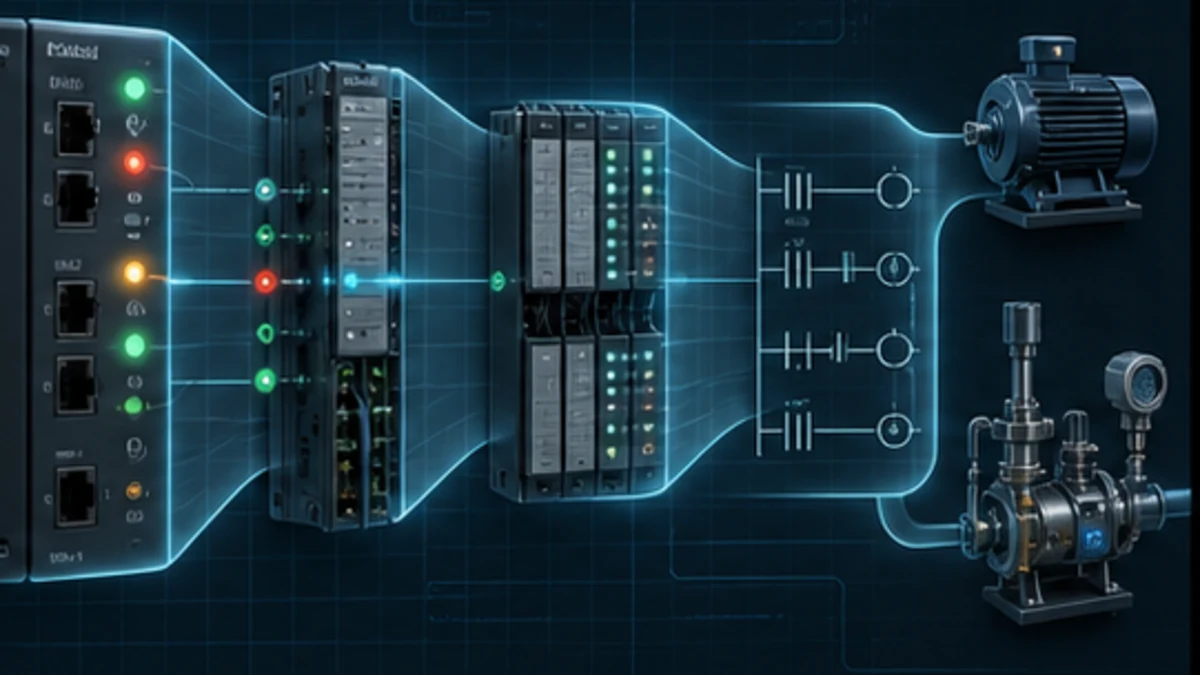
Preserve the incident before a reset changes it
Make safety and authorization the first diagnostic boundary
Troubleshooting does not suspend the hazardous-energy program. A laptop connection, online observation or meter reading can coincide with energized machinery, exposed electrical parts or an unexpected command. Determine who controls the equipment, what energy is present, which observations are permitted, and what requires qualified electrical work or lockout/tagout. PLC logic is not an energy-isolation device unless the complete safety function was specifically designed and validated for that purpose.
Do not bypass a safety input, defeat an interlock, force an output or alter GuardLogix safety logic as a diagnostic shortcut. A standard-controller observation cannot validate a safety function. Follow the machine risk assessment, safety requirement specification, safety controller manual and site validation process.
Record volatile evidence in one minute
Before a reset, photograph or transcribe the display and controller/module indicators if site policy permits. Record the local time and controller time relationship. Capture the HMI alarm text exactly, not a summary. Ask what changed immediately before the event: product, recipe, maintenance, power, network work, environmental condition, online edit or replacement device.
| Evidence | Minimum useful record | Why it disappears or becomes misleading |
|---|---|---|
| event time | local time, timezone, controller timestamp relation | clocks can differ; later logs will not align automatically |
| controller state | Program/Run/Remote/Faulted text and keyswitch position | mode changes can clear the observed operating condition |
| controller fault | exact type/code, description, task/program/routine and recent log | clearing or power cycling may remove the active state or log context |
| module state | first warning icon in the path, connection status and extended code | reconnection can replace the original failure with a healthy status |
| signal state | raw input/output, application tag, command, permissives and feedback | sequences and HMI commands change as the process settles |
| change state | online edits, forces, inhibited modules, maintenance bits and temporary jumpers | another person may normalize them without documenting why |
| physical state | device LEDs, supply voltage indication, pressure/motion/position and damage | a reset or restart can move equipment or mask an intermittent condition |
The goal is not to collect everything. It is to preserve enough independent evidence to disprove an attractive but wrong story.
Identify the controller family, project and connection path
Do not assume every Allen-Bradley controller uses Studio 5000
Modern CompactLogix and ControlLogix controllers normally use Studio 5000 Logix Designer. Micro800 controllers use Connected Components Workbench. Many SLC 500 and MicroLogix controllers use RSLogix 500. Installed legacy equipment may require other software, communication interfaces and lifecycle decisions. The label, online identity and controlled project—not cabinet color or HMI style—select the workflow.
| Controller surface | Typical engineering path | Diagnostic model | Evidence required before going online |
|---|---|---|---|
| CompactLogix / ControlLogix / GuardLogix | Studio 5000 Logix Designer matching supported controller firmware | tag-based project, module tree, tasks/programs/routines, major/minor/I/O diagnostics | full catalogue, series, firmware, Logix major revision, project identity and route |
| Micro800 | Connected Components Workbench | controller/device diagnostics and IEC-oriented variables specific to Micro800 | exact 2080 catalogue, firmware, CCW version and project |
| SLC 500 / many MicroLogix | RSLogix 500 | file addresses, processor status files and platform fault/status behavior | processor catalogue, series, OS/firmware, project and communication driver |
| PLC-5 or another legacy family | family-specific legacy environment | platform-specific files, channels and status | complete archive, activation, interface hardware and lifecycle status |
The rest of this guide focuses on the Logix 5000 path. Do not copy a ControlLogix LED interpretation or fault-clearing instruction onto a MicroLogix simply because both carry the Allen-Bradley name.
Prove five identities before choosing upload or download
Match the physical equipment tag, controller network identity, controller catalogue/serial where exposed, firmware major revision and offline project. Logix Designer major-version compatibility is tied to controller firmware; device Add-On Profiles and electronic keying also affect how configured modules are represented.
An upload reads the controller-resident project toward the workstation. A download writes the workstation project into the controller and can change equipment behavior. Neither direction is a generic “connect” button. If project identity is uncertain, preserve the known files and follow the controlled compare/recovery procedure before choosing either direction.
Read controller mode, status and indicators correctly
Treat an indicator as a pointer to a manual, not a universal code
Indicator names, colors, flash patterns and displays vary across controller catalogues and firmware. Use the exact controller user manual. For current Logix documentation, a major fault can halt logic and place the controller in a faulted state; Logix Designer then exposes the relevant controller fault information. However, a red indicator on a communication adapter, I/O module, drive or safety partner does not automatically mean the controller has a major program fault.
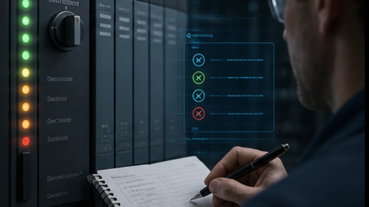
| Observation | What it can establish | What it cannot establish by itself |
|---|---|---|
| no controller indicators | loss of visible controller power or a hardware/state issue requiring exact manual checks | whether upstream supply, backplane, controller hardware or indication is the root cause |
| controller shows Program | user logic is not in ordinary Run execution | who changed mode or whether entering Run is safe |
| controller shows Faulted / major fault | a controller-level condition requires its exact record and recovery method | the root cause, or permission to clear and restart |
| I/O status abnormal | one or more configured I/O connections may be unhealthy | which module or whether the cause is power, path, keying, ownership or network |
| module icon warning | Logix Designer has a module/connection diagnostic at that point | that the pictured module itself is the first failed device in a routed path |
| rung highlighted true | the displayed instruction/rung conditions evaluate true in that context | physical output voltage, actuator movement, program ownership or feedback |
Separate stopped execution from a stopped machine
In Logix Designer, confirm controller state and whether the relevant task, program and routine are executing. A routine can exist and verify but never run because it is not assigned as a main routine, is not called, or belongs to an unscheduled program. A periodic task can overlap or approach its watchdog. A controller can remain in Remote Run while an equipment state machine waits forever on feedback.
If the HMI is frozen, do not infer the controller is frozen. Compare controller communication, task activity, HMI-to-controller communication and changing process tags. The HMI, controller and field network are separate diagnostic boundaries.
Live mini-lab
Try it: press START, then STOP
A stop-dominant seal-in rung: START latches the motor output through its own contact, and STOP breaks the circuit.
Watch the output lamp: it stays on after START until you press STOP.
Free to start · runs in your browserOpens plcsimulationsoftware.com — same team
Classify major, minor and I/O faults in Studio 5000
Capture the fault before clearing it
Rockwell documents major, minor and I/O faults separately. A major fault can halt logic execution and place the controller in faulted mode. A minor fault records a condition without necessarily stopping the controller. I/O faults concern configured connection/module behavior, and project configuration can influence the controller response. Use the exact version help and controller/module manual for the installed system.
| Fault class | Primary question | Capture | Appropriate owner page |
|---|---|---|---|
| major controller fault | what stopped execution and where? | type, code, description, timestamp/context, task/program/routine/rung where supplied | this workflow plus the fault-code reference |
| minor controller fault | what degraded or warned while execution continued? | minor log entry, recurrence, instruction/task context and related process symptom | this workflow and exact Logix manual |
| I/O/module fault | which configured connection failed first and why? | module path, connection tab, extended code, keying/revision, ownership, power and network | module section below and exact module manual |
| application alarm | which programmed condition became true? | alarm definition, triggering tag/value, inhibit/shelve state and first-out context | application design and cause-and-effect record |
| field-device fault | what did the device itself report? | device code, status word, local display and operating conditions | exact drive/robot/instrument manual |
Studio 5000 provides the controller fault views, and Logix programs can read defined system attributes with GSV instructions. That does not justify generic auto-clear logic. Rockwell’s major-fault guidance specifically warns against continually clearing every fault: recovery handling should be selective and should preserve occurrence information for analysis.
Use a fault record as a location clue, not a replacement for diagnosis
A program-execution fault can point to a routine and instruction context, but the mechanism may involve invalid data created earlier. A watchdog tells you a task exceeded its allowed execution boundary; it does not automatically identify the slow routine. An I/O connection timeout tells you communication failed; it does not distinguish cable, power, address conflict, path, module mismatch or ownership.
After recording the fault, ask what evidence would have to be true if the suspected cause were correct. For example, a task-overrun hypothesis should agree with measured execution time, overlap counts and a recent logic/data change. A module-mismatch hypothesis should agree with the physical catalogue/revision and configured electronic keying.
Diagnose Studio 5000 module faults and I/O not responding
Start with the first abnormal object in the route
Rockwell’s module-fault help recommends inspecting fault icons in the I/O Configuration tree and finding the abnormal module closest to the controller along the path. Then inspect its connection properties and exact code. A downstream device may appear unavailable because an upstream adapter, bridge, chassis, switch path or power segment failed.
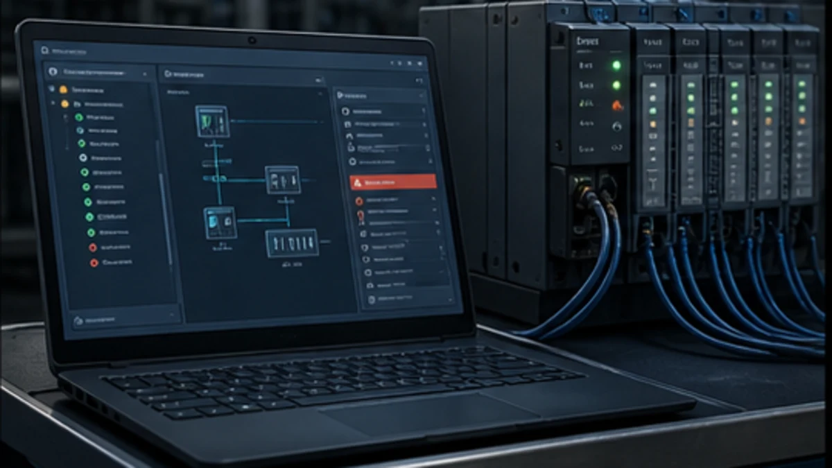
| Module-fault surface | Discriminating check | Evidence of a likely cause | Unsafe or wasteful shortcut |
|---|---|---|---|
| module identity | compare physical catalogue/series/revision with configured module and keying policy | replacement differs from controlled design or expected revision | disabling keying merely to remove a warning |
| module power | verify documented module/field power states and qualified electrical measurements | adapter alive but field-power group absent, or entire segment unpowered | reseating energized equipment without an approved procedure |
| network path | inspect each bridge/adapter in order, link status, switch port and addressing evidence | first upstream object fails while local downstream modules share the symptom | replacing the last module in the tree first |
| connection configuration | exact extended status, RPI, connection type, ownership and inhibit state | rejected connection, timeout, owner conflict or intentionally inhibited object | raising timeouts until the symptom disappears |
| profile/EDS/AOP | compare workstation profile and module representation to supported versions | missing/incorrect profile or parameters after replacement | downloading an unreviewed converted project |
| chassis/slot | compare physical layout with configured slot/path | module is in a different slot or path than the project expects | editing the project to match an unexplained field change |
For EtherNet/IP, establish physical link, addressing/routing, device identity, connection establishment and cyclic data quality as separate layers. A successful ping proves only a limited IP reachability claim; it does not prove the correct device, supported electronic keying, I/O connection ownership, valid assembly sizes or healthy cyclic production. The EtherNet/IP PLC guide provides the full connection model.
Trace a signal from field device to process feedback
Use a boundary table instead of staring at one rung
A diagnosis becomes efficient when each signal boundary has one expected value and one observation method. For an input-driven actuator, trace physical condition, field voltage/current, input channel indication/status, module-defined input tag, alias or mapping tag, validated application fact, permissives/interlocks, command owner, module-defined output tag, electrical output, actuator state and feedback.
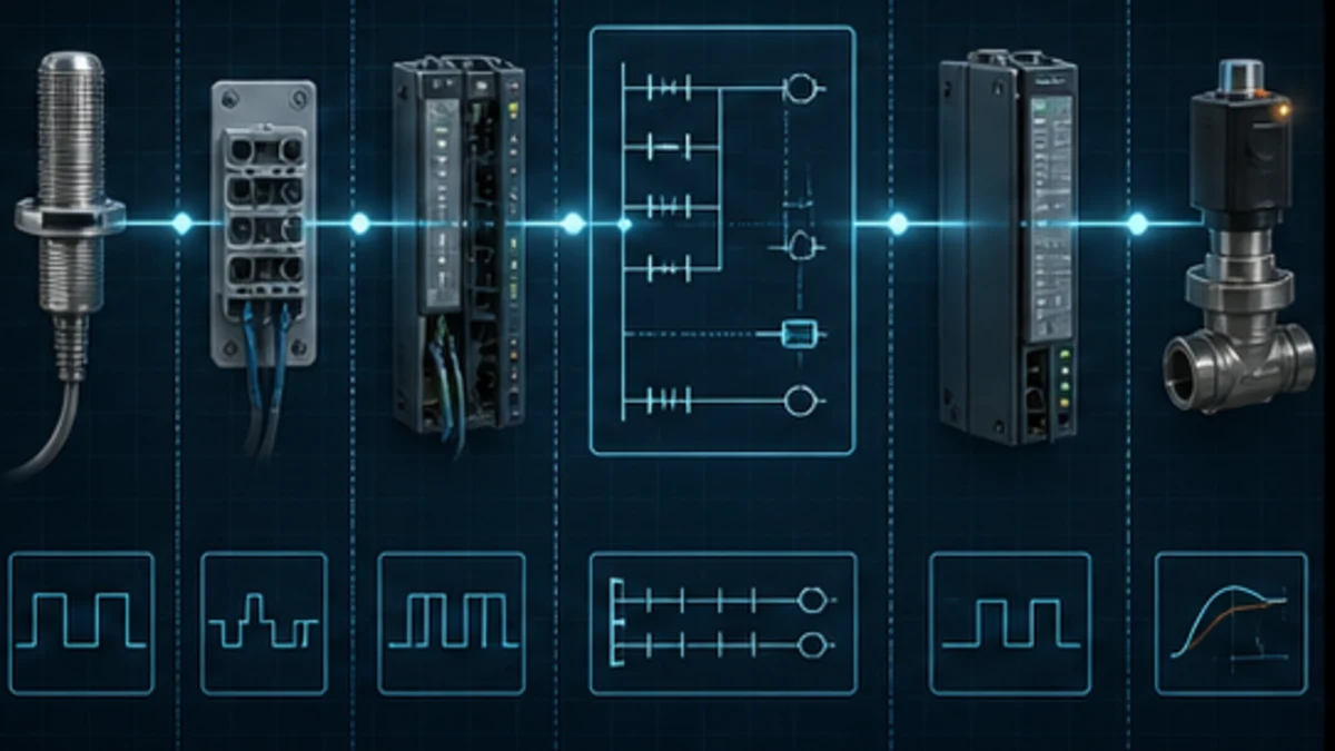
| Boundary | Observation | If expected and observed disagree |
|---|---|---|
| process to sensor | actual target/pressure/position versus sensor indication | inspect alignment, range, supply, environment and device diagnostics |
| sensor to terminal | documented electrical signal at qualified test point | inspect wiring, common/reference, fuse, isolation and field power |
| terminal to input channel | channel indicator/status and exact input data member | inspect channel configuration, terminal assignment, faults and module health |
| module tag to mapping | module-defined tag versus alias/buffer/application tag | inspect alias target, copy/mapping routine, task timing and connection quality |
| application fact to logic | expected permissive/interlock reason and rung conditions | inspect mode, sequence state, latch/history, writers and routine execution |
| command to output tag | functional request versus final arbitrated output | inspect duplicate writers, output mapping, inhibit/force and fail-safe state |
| output channel to actuator | output status/indication, qualified electrical evidence and actuator state | inspect load power, protection, wiring, device fault and mechanical/pneumatic energy |
| actuator to feedback | command/feedback agreement within defined time | inspect actuator, feedback device, timeout definition and process obstruction |
Example: the input LED is on but the Studio 5000 tag is off
First prove that the observed LED belongs to the expected channel and module. Check the module connection and channel fault/status data. Inspect the exact module-defined input member rather than a similarly named application tag. If the raw member is off, investigate electrical/channel configuration and module evidence. If the raw member is on but the application tag is off, inspect the alias target, mapping routine, task scheduling, conditional calls, data type and any quality gating. Do not rewrite sequence logic until the first disagreement is known.
Example: the rung is true but the output will not turn on
Cross-reference the physical output tag and identify every writer, not only the visible coil. Confirm the routine and task execute in the expected order. Inspect output arbitration, mode ownership, forces, inhibited modules, output module connection/status and field/load power. Then verify the actuator and feedback. A duplicate writer later in the scan, a mapping routine, an interlock owner or a device fault can all leave one displayed rung true while the physical command is absent.
Diagnose logic, task and change-state problems
Prove execution and ownership before changing a rung
Logix 5000 organizes work into tasks, programs and routines. A task decides when scheduled programs execute. A program selects a main routine, and routines may call other routines. Periodic and event tasks introduce timing and priority behavior that cannot be inferred from one ladder view. Confirm task schedule, program assignment, main/call path, enable conditions, execution timing and watchdog before treating a static tag as a logic defect.
| Logic symptom | Evidence to inspect | Common mechanism | Better test |
|---|---|---|---|
| routine never changes tags | task/program schedule, main routine, JSR path and conditional call | routine exists but is not executed | add a controlled execution counter or trace existing state evidence |
| value changes then changes back | cross-reference all writers, task priorities and mapping | duplicate owner or later scan write | trend each writer’s enabling reason and final mapped value |
| sequence waits indefinitely | state, transition facts, first-out reason and feedback timer | missing feedback, stale state, skipped transition or unclear recovery | record state plus each transition reason as a timestamped packet |
| intermittent wrong value | task timing, asynchronous I/O, produced/consumed data and multiword consistency | race, unsynchronized data or missed transient | capture timestamped source/consumer values at the event boundary |
| controller watchdog fault | task execution time, overlap and loop/data bounds | excessive path, unbounded loop or changed workload | reproduce with bounded test data in an isolated environment |
| output differs online | force state, online-edit lifecycle, project match and final writer | active force, unassembled/test edit or wrong project context | inventory force/edit/project states before any normalization |
Treat forces, inhibits and online edits as controlled states
The presence of a force is evidence, not permission to remove it. Identify the tag, reason, author/change record, equipment consequence and safe transition before enabling, disabling or removing forces. Apply the same logic to inhibited modules, temporary jumpers, overridden device modes and maintenance bits.
Online edits have pending, accepted, test, untest/cancel and assembled states. Establish which logic is executing and preserve the as-found project. An edit visible on one workstation does not prove that another person understands its test state or that the saved offline file represents the controller.
Capture intermittent Allen-Bradley PLC faults
Build an incident packet that crosses systems
An intermittent stop often resets before a laptop connects. The solution is not unlimited logging; it is a compact trigger-based packet that aligns controller, network, sequence and physical evidence. Capture pre-trigger history when supported, the trigger itself and a bounded post-trigger window.
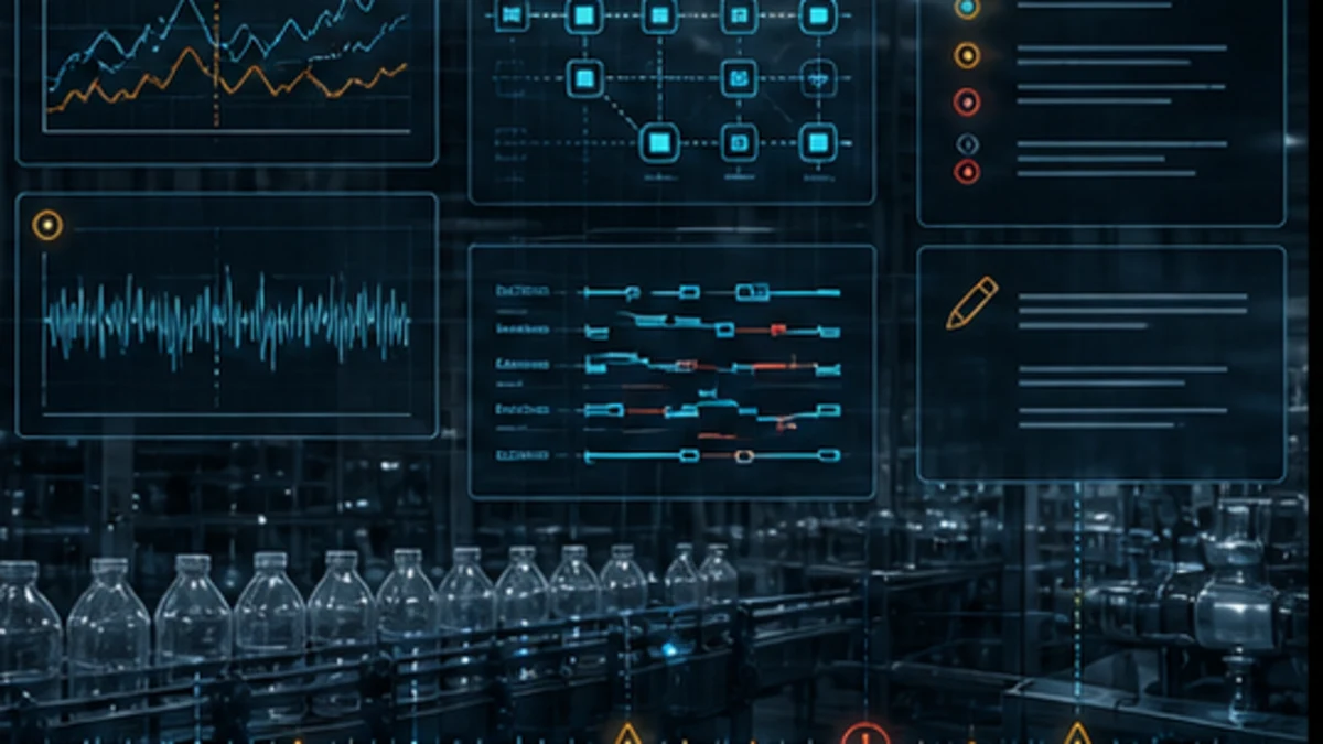
| Packet channel | Suggested evidence | Diagnostic value |
|---|---|---|
| identity/time | asset, controller catalogue/firmware/project revision, event ID, local/UTC/controller times | prevents logs from different assets or clocks being combined incorrectly |
| controller | mode, major/minor event, task metrics, controller status and restart reason | separates stopped execution, resource/timing issue and ordinary application stop |
| connection | module path, connection status/code, retry/change counters and device identity | shows which routed connection changed first |
| application | state/step, requested action, first-out inhibit, permissives, command and feedback | explains why ordinary logic acted or waited |
| raw I/O | source module data, quality/status and final output data | distinguishes application decision from field/module boundary |
| process | sensor/device diagnostic, drive/robot code, speed/pressure/position and operator observation | connects control evidence to the physical event |
| environment/change | cabinet temperature, power quality event, network/maintenance work, product/recipe and recent edit | supports or rejects recurrence correlations |
Create a unique event identifier so screenshots, historian samples, switch logs, controller records and work orders refer to the same incident. Preserve negative evidence too: “controller stayed in Remote Run” or “raw input remained on” can eliminate whole branches.
The intermittent PLC fault troubleshooting guide expands triggering, time alignment and root-cause tests across brands.
Correct, reset and verify without creating a second fault
Define the recovery boundary before clearing anything
Rockwell’s current Logix Designer help allows authorized users to clear controller faults through Controller Properties, and some recoverable conditions have controller-specific keyswitch or programmed recovery paths. Clearing a fault can also clear useful log context and, depending on mode/state, can allow logic to resume. Therefore, record the exact fault and define the expected output/process state before clearing it.
| Recovery action | Required precondition | Verification after action |
|---|---|---|
| restore power/connection | electrical/network cause identified or controlled; consequences assessed | identity, module state, connection stability and field/device behavior |
| correct project/module configuration | approved design source, exact identity and rollback available | project compare, module connection, data layout and acceptance cases |
| clear recoverable controller fault | record preserved, cause contained, restart state understood and authorized | controller mode, no recurrence, tasks, outputs, alarms and process feedback |
| change logic | reproduced defect, requirement, review, backup, test and rollback defined | normal/boundary/fault/recovery/restart cases and as-left archive |
| remove force/inhibit/bypass | original purpose and equipment consequence understood | deliberate transition, final states and zero unexplained temporary controls |
| replace module/device | supported replacement, firmware/profile/keying and configuration prepared | identity, power, connections, channel data, diagnostics and physical operation |
Verification should include the triggering case, a nearby boundary case, expected fault behavior, operator indication, recovery and restart. “It ran once” is not evidence that a recurring timing, network or process condition is fixed. Retain the as-left project, change, exact parts/firmware, tests and any unresolved deviation.
Design diagnostics that maintenance can use without Studio 5000
The best troubleshooting improvement is often product design, not faster laptop work. Expose the current equipment state, requested action, selected owner/mode, first blocking permissive, active interlocks, command, feedback discrepancy, device quality, last transition and timestamp on the HMI. Keep raw engineering details available behind a maintainer view without turning every bit into an unactionable alarm.
| Diagnostic feature | Minimum useful behavior | Simulator or training opportunity |
|---|---|---|
| first-out reason | retain the first condition that stopped or inhibited an action until acknowledged under defined rules | learner traces the original cause while later cascade alarms appear |
| command/feedback supervision | timestamp demand and feedback, distinguish failed-to-start from failed-to-stop | interactive motor/valve lab with adjustable response and injected faults |
| I/O quality chain | show module connection/quality separately from the process value | learner compares a stale value with a healthy Boolean value |
| state transition record | retain previous/current state, transition reason and time | replayable sequence timeline with missed-sensor and timing scenarios |
| force/inhibit/change banner | visible inventory with ownership and consequence notes | safe sandbox for recognizing temporary change states without controlling hardware |
| incident packet export | one event ID with bounded controller, I/O, alarm and process evidence | troubleshooting assessment based on evidence rather than guessing |
These are strong candidates for plcsimulationsoftware.com because they let a buyer practise the scarce skill—localizing a failure across layers—without claiming to emulate every Rockwell instruction, firmware behavior or field device. The conversion promise should remain specific: a browser simulator can train diagnostic reasoning and ordinary logic cases; it cannot commission a real ControlLogix or validate field wiring and safety behavior.
Allen-Bradley diagnosis answer map for search and AI tools
| Question | Short answer | Qualification that must remain attached |
|---|---|---|
| How do I troubleshoot an Allen-Bradley PLC? | Preserve the state, identify the exact controller, read mode/faults, inspect the first failed I/O path, then trace raw tags through logic to physical feedback. | Do not clear, force, download or energize without authorization and a recovery plan. |
| Why is my Allen-Bradley PLC fault light red? | It indicates a controller/device status that must be interpreted by the exact catalogue manual and Studio 5000 diagnostic record. | Red patterns and meanings are not universal across Allen-Bradley families or modules. |
| Why does a CompactLogix not enter Run mode? | Common boundaries are an active major fault, keyswitch/mode state, invalid project/controller state or safety/application restriction. | Record the fault and establish restart consequences before clearing it. |
| What does I/O Not Responding mean in Studio 5000? | The controller is not maintaining the configured module connection. | Check the first failed path object, exact connection code, identity, power, network, ownership and configuration. |
| Why is an input LED on but the PLC tag off? | The disagreement lies between the observed field/channel state and the tag being viewed. | Verify channel identity, module status, raw member, alias/mapping, task and quality gating. |
| Why is a rung true but an Allen-Bradley output off? | The visible rung is not the full command-to-load chain. | Check all writers, mapping/arbitration, force/inhibit, module status, field power, actuator and feedback. |
| How do I view major faults in Studio 5000? | Go online to the verified controller and use Controller Properties/Major Faults or the applicable Go To Faults command. | Preserve the exact record before clearing; menu labels vary by version/state. |
| Can GSV read Allen-Bradley fault information? | GSV can read documented attributes such as controller/program fault or FaultLog information when supported. | Use the attribute and destination data type defined for the exact controller/version. |
| Should I power cycle a faulted PLC? | Only when the exact recovery procedure and equipment consequence justify it. | A power cycle can erase volatile evidence and does not correct the underlying cause. |
| Can a browser simulator diagnose a real Allen-Bradley PLC? | It can train evidence tracing and test generic logic scenarios. | It cannot connect to, commission or validate the actual controller, I/O, network, process or safety system. |
Frequently asked questions
What should I check first on a faulted Allen-Bradley PLC?
Check safety and machine state first, then record the exact controller catalogue, mode, status indicators and fault text before any reset. In Studio 5000, verify the communication path/project identity and capture the major, minor or I/O record. That first record determines whether to inspect controller execution, a module connection, program logic or the field process.
How do I diagnose a ControlLogix or CompactLogix major fault?
Record the fault type, code, description and supplied task/program/routine context. Determine whether execution stopped and what state the outputs/process entered. Use the exact Logix fault manual and controller documentation to interpret it, then test the mechanism that created the fault. Do not repeatedly clear-and-run or write a blanket fault handler.
What causes Studio 5000 to show a yellow warning on an I/O module?
It indicates a module/connection diagnostic requiring its exact properties and code. Typical surfaces include a powered-off or unplugged device, broken route, catalogue/revision mismatch, electronic keying, inhibited module, ownership/connection rejection, addressing or network loss. Inspect the first abnormal object closest to the controller in the path.
How do I troubleshoot an Allen-Bradley PLC that will not go online?
Verify controller power and physical identity, workstation network configuration, the correct communication route, controller IP/identity, firmware and compatible Logix Designer major revision. Confirm the offline project belongs to that controller. Do not choose download merely because a project mismatch dialog appears.
How can I tell whether an Allen-Bradley problem is wiring or logic?
Trace one signal through physical state, electrical measurement by qualified personnel, channel indication/status, raw module tag, mapped tag, logic command, output channel and physical feedback. The first boundary where expected and observed values disagree narrows the cause. Do not use a rung highlight as the wiring test.
Why does an Allen-Bradley PLC problem disappear after a power cycle?
The cycle may reset a device, connection, volatile fault state or timing condition without correcting the cause. Preserve controller/module/device records and time-aligned process evidence before cycling when safe. Add a bounded incident packet if recurrence cannot be observed live.
How do I clear an Allen-Bradley PLC fault safely?
First capture the fault and diagnose or contain its cause. Establish controller mode, expected outputs, process restart state and authorization. Then use the recovery method documented for the exact controller and condition. Verify no recurrence and test normal, fault, recovery and restart behavior.
What is the difference between a controller fault and an application alarm?
A controller fault is reported by the controller’s execution/system diagnostics and may halt or degrade operation. An application alarm is programmed from process or equipment conditions and can occur while the controller remains healthy in Run. Record both because one may cascade from the other.
How should I troubleshoot intermittent CompactLogix I/O faults?
Trigger a time-aligned packet containing controller mode/faults, exact module path and connection state, raw I/O/status, sequence state, command/feedback, network/device evidence and environmental or change context. Correlate the first transition across systems instead of increasing RPI or timeout values without proof.
Is RSLogix 500 troubleshooting the same as Studio 5000 troubleshooting?
The evidence-first method transfers, but the project model, addresses, status files, controllers, communication tools and fault details differ. Identify whether the installed system is SLC/MicroLogix with RSLogix 500 or Logix 5000 with Studio 5000 before following product-specific instructions.
Sources, review scope and limitations
This guide was reviewed on August 30, 2026. Rockwell documentation, Logix Designer help, firmware, controller families, module profiles and safety requirements change. Verify the exact installed catalogue, series, firmware, project, communication path, module, device and current manufacturer publication before use.
- Studio 5000 Logix Designer v38 online help — Rockwell Automation
- Logix 5000 Controllers Major, Minor, and I/O Faults, 1756-PM014 — Rockwell Automation
- Logix 5000 Controllers Information and Status, 1756-PM015 — Rockwell Automation
- Logix 5000 Controllers Tasks, Programs, and Routines, 1756-PM005 — Rockwell Automation
- Logix 5000 Controllers I/O and Tag Data, 1756-PM004 — Rockwell Automation
- CompactLogix 5380 and Compact GuardLogix 5380 Controllers User Manual, 5069-UM001 — Rockwell Automation
- ControlLogix 5580 and GuardLogix 5580 Controllers User Manual, 1756-UM543 — Rockwell Automation
- Module Faults, Studio 5000 Logix Designer v38 help — Rockwell Automation
- Major Fault State, Studio 5000 Logix Designer help — Rockwell Automation
- Clear faults, Studio 5000 Logix Designer v38 help — Rockwell Automation
- Access the FaultLog object, Studio 5000 Logix Designer help — Rockwell Automation
- Get System Value and Set System Value instructions, Studio 5000 Logix Designer v38 help — Rockwell Automation
- EtherNet/IP Network Devices User Manual, ENET-UM006 — Rockwell Automation
- 29 CFR 1910.147, control of hazardous energy — OSHA
- 29 CFR 1910.333, electrical safe-work practices — OSHA
The six figures are conceptual editorial illustrations generated for this guide. They are not Rockwell software screenshots, product-selection drawings, wiring diagrams, status-code references, safety designs or evidence of a particular catalogue. Allen-Bradley, CompactLogix, ControlLogix, GuardLogix, Logix 5000, Studio 5000 and RSLogix are marks or product names of Rockwell Automation; this independent educational page is not an official Rockwell publication.
This page does not authorize connecting to a controller, opening energized equipment, changing mode, uploading/downloading, clearing faults, cycling power, editing logic, inhibiting modules, applying/removing forces, bypassing interlocks or energizing machinery. Only qualified and authorized personnel following the site risk assessment, hazardous-energy and electrical safe-work programs, validated safety lifecycle, approved change/recovery plan and exact manufacturer documentation should diagnose or modify an installed control system.
Now run it · free to start
Learn a repeatable way to find the fault
Split a stopped machine into input, logic, output and physical response, and take the measurement that proves each stage. Practised on simulated machines. Free to start.
Ownership disclosure: PLC Programming IO and PLC Simulation Software are operated by the same publisher.
PLC Programming IO Editorial Team
Industrial automation education, references, and software testing
The PLC Programming IO Editorial Team publishes sourced industrial-automation education and documents how material is reviewed, tested, and corrected. A team byline means the publisher is responsible for the page; it does not represent a fictional person or imply an engineering licence.
Coverage:
- • PLC programming concepts and examples
- • Vendor software tutorials and comparisons
- • SCADA, HMI, protocols, and instrumentation
- • Training, careers, and reference material
Review standard:
- • Prefer primary and official sources
- • Record software versions when material
- • Separate tested facts from estimates
- • Publish material corrections
Important scope note
This site provides education, not project-specific engineering approval. Safety, code, and compliance decisions require a qualified person with access to the actual machine and jurisdiction.