Allen-Bradley PLC Programming and Troubleshooting Guide
Choose the correct Rockwell controller software, structure a Logix project, map tags to I/O, test ladder logic and troubleshoot with version-scoped evidence.
Review status: Editorially reviewed against cited Rockwell Automation v38 online help, current programming manuals, controller documentation and OSHA requirements; exact controller, firmware, software build, edition, activation, project, safety validation and site procedures require verification
Direct answer
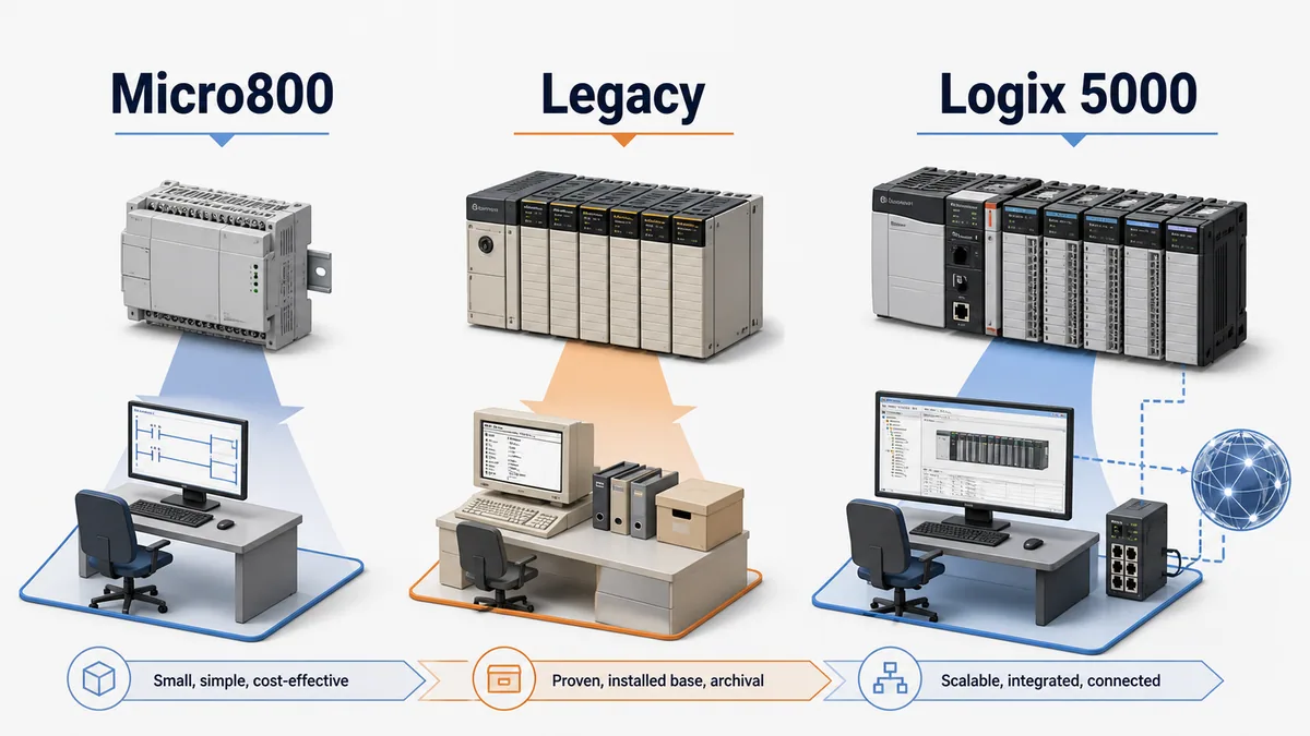
Allen-Bradley PLC programming begins by identifying the exact controller family and catalogue number, because “Allen-Bradley” does not identify one programming environment. Modern CompactLogix and ControlLogix controllers use Studio 5000 Logix Designer and a tag-based Logix 5000 project. Micro800 controllers use Connected Components Workbench (CCW). Many installed SLC 500 and MicroLogix controllers use RSLogix 500 and file-based addresses. PLC-5 and other legacy systems have still different lifecycle and software requirements.
For a modern Logix project, match the Logix Designer major version to the controller firmware major revision, create the correct controller project, configure the actual I/O and communications modules, define descriptive tags or aliases, organize execution into tasks, programs and routines, implement ordinary control logic, verify it, and test it against a written cause-and-effect specification. A program that verifies without errors is not automatically safe, complete or correct.
Troubleshoot from observable evidence outward: confirm controller identity and mode, capture major/minor and I/O diagnostics, inspect module connection state, compare the raw I/O tag with its alias and application tag, then follow the logic to the process feedback. Do not download, flash firmware, force I/O, assemble an online edit or clear a fault until the consequence and recovery path are understood and authorized.
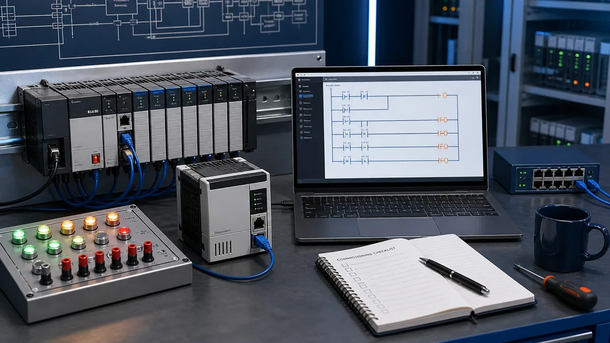
Choose the controller family before the software
Separate the three common programming paths
| Installed controller path | Typical engineering environment | Project/data model | First identification evidence |
|---|---|---|---|
| Micro800 family | Connected Components Workbench | IEC-oriented variables, programs and device configuration specific to Micro800 | full 2080-series catalogue number, firmware and CCW compatibility |
| SLC 500 or many MicroLogix systems | RSLogix 500 | file-based data addresses such as input, output, binary, timer and integer files | processor catalogue, series, firmware, existing project and communication path |
| CompactLogix or ControlLogix | Studio 5000 Logix Designer | controller/program tags, user-defined data types, tasks, programs and routines | controller catalogue, firmware major revision, project revision and installed Logix Designer versions |
| GuardLogix or Compact GuardLogix | Studio 5000 Logix Designer plus the applicable safety workflow | standard and safety tasks/tags under safety signatures, locking and validated lifecycle controls | exact safety controller/partner, safety manual, firmware, application signature and validation record |
| PLC-5 or other legacy platform | legacy product-specific environment and migration tooling | platform-specific file addressing and instruction behavior | complete hardware/software archive, activation, communication interface and lifecycle status |
Do not select Studio 5000 merely because the panel contains an Allen-Bradley logo. CCW is not Logix Designer, and RSLogix 500 is not RSLogix 5000/Studio 5000. A file from one project family is not a native project for another, even when familiar ladder mnemonics appear in both.
Build a compatibility evidence sheet
Rockwell’s current ControlLogix documentation states that controller firmware and Logix Designer must use the same major revision: a 38.xxx controller, for example, requires Logix Designer version 38. The exact minor build, Windows version, FactoryTalk services, add-on profiles, electronic data sheets, device firmware and activation still need compatibility review in the Product Compatibility and Download Center (PCDC).
| Evidence field | Example form | Why it controls the work |
|---|---|---|
| controller catalogue and series | exact characters from label and online identity | determines supported firmware, memory, ports and features |
| controller firmware | major.minor build | selects compatible Logix Designer major revision and feature set |
| project revision and source hash | ACD/L5X archive plus controlled checksum | distinguishes known source from an unrelated laptop copy |
| engineering software | product, major/minor build and edition | controls opening, editing, languages and licensed features |
| workstation | Windows build, patches, services, drivers | affects installation and communication compatibility |
| device profiles | AOP/EDS versions for configured modules | affects module identity, configuration and produced data structures |
| activation/support | entitlement and recovery path | prevents a maintenance window from depending on an unavailable licence |
| controller ownership | equipment tag, network path and physical identity | prevents connecting to or downloading into the wrong asset |
An “upload” can recover controller-resident project content, but it does not recreate every external dependency, design decision, HMI application, drive parameter archive, safety proof or source-control history. Preserve the known project and its supporting records before relying on controller recovery.
Understand the Logix 5000 execution model
Read tasks, programs and routines as different objects
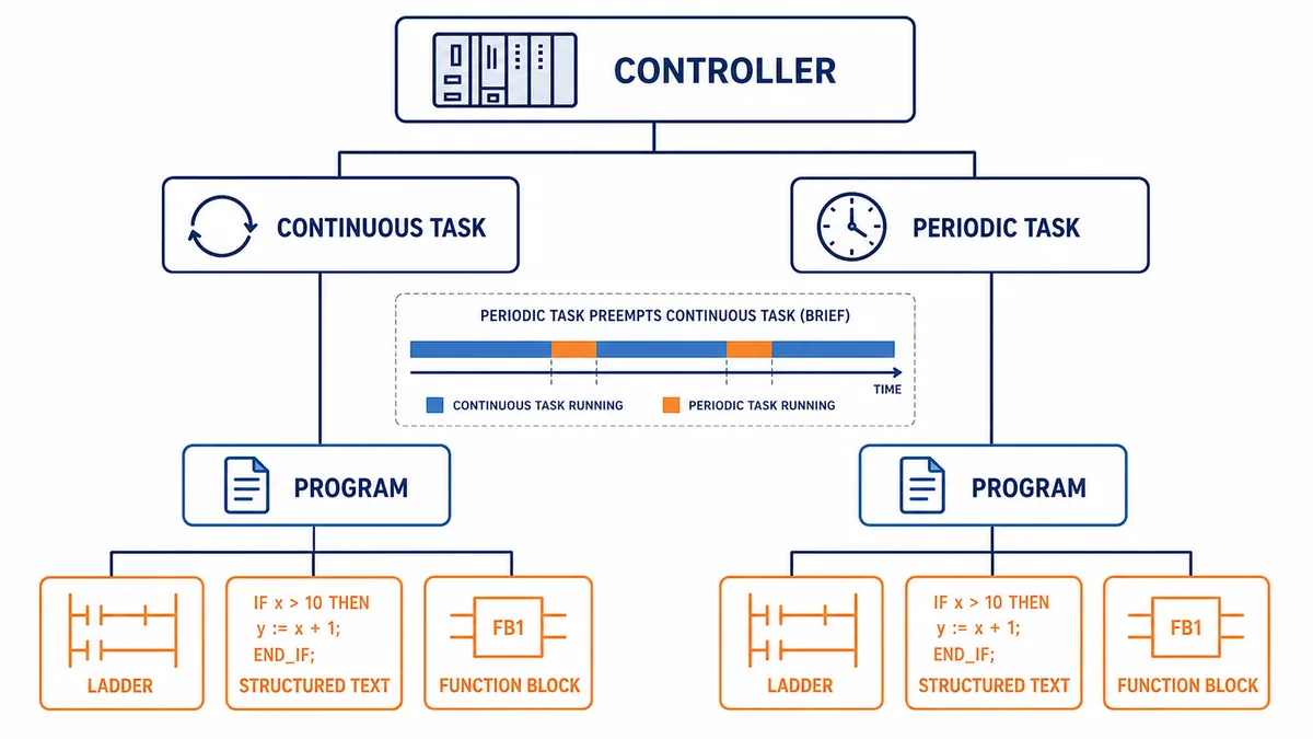
In a Logix Designer project, a task schedules execution, a program groups related routines and program-scoped data, and a routine contains executable logic in one supported language. The default MainTask is continuous. Periodic tasks run at configured intervals and priorities; event tasks run when supported triggers occur. Higher-priority tasks can preempt lower-priority work.
| Object | Primary responsibility | Common design error | Evidence to retain |
|---|---|---|---|
| task | when and at what priority scheduled programs execute | placing time-critical and background work together without timing proof | type, rate/trigger, priority, watchdog, overlap and execution time |
| program | functional ownership, scheduled order, main routine and optional fault routine | duplicating ownership of one command across programs | purpose, scheduled task/order, parameters/tags, main/fault routines |
| routine | one executable logic block in ladder, structured text, function block or supported language | assuming a routine executes because it exists | language, caller/main assignment, test coverage and revision |
| controller tag | controller-wide data and I/O-produced structures | broad write access and unclear ownership | data type, producer/writers, consumers and initial/retention assumptions |
| program tag/parameter | program-local data or defined inter-program interface | hidden coupling or inaccessible data across programs | scope, direction, connection and acceptance behavior |
Prove timing instead of assuming one scan
The phrase “PLC scan” can hide the scheduler. A continuous task restarts after it finishes, but periodic and event tasks can interrupt it. Programs within a task execute in their scheduled order, and routines execute only through main-routine designation or explicit calls. I/O updates, communications, produced/consumed data and module requested packet intervals have timing relationships that are not identical to a single legacy input-logic-output sweep.
| Timing question | Required evidence | Risk if ignored |
|---|---|---|
| how often must this logic run? | process requirement, task period/trigger and measured execution time | missed events, excessive jitter or needless CPU load |
| can a higher-priority task interrupt it? | task priorities, overlap and shared-data analysis | inconsistent multiword data or sequence race |
| what happens if execution exceeds the watchdog? | configured watchdog, worst-case execution and fault response | major fault and stopped control logic |
| when does field data change? | module connection/RPI, input timestamp behavior and task use | reasoning from stale or asynchronously changing data |
| can two tasks write the same tag? | cross-reference and ownership review | nondeterministic final value dependent on scheduling |
| what is the restart behavior? | power-up/controller mode transition tests and stored state | unintended output, skipped initialization or stale sequence state |
Use task monitor and trend evidence where available, but test worst-case paths: error-handling branches, communication timeouts, loops, array operations, messages and simultaneous events. The configured watchdog is a last boundary, not a performance target.
Map field I/O into descriptive application tags
Keep physical data, aliases and application state distinct
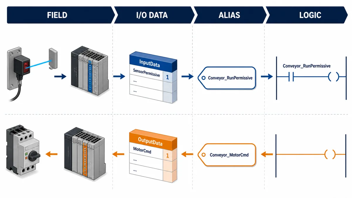
When a Logix I/O module is added to the I/O Configuration tree, Logix Designer creates controller-scoped module-defined tags. Names encode location/slot/type and members such as input, output, configuration or status data according to the module profile. The exact structure is module-specific.
An alias can give a physical point a meaningful name, such as Conveyor_PE_Infeed, without copying it. A buffered application tag is different: logic copies input data at a controlled boundary, validates it, and uses the stable copy. Neither pattern is universally correct; document whether a tag is direct I/O, alias, mapped/buffered state, HMI command, sequence state or output request.
Define a tag contract before writing rungs
| Tag category | Example naming intent | Allowed writers | Required quality/fault behavior |
|---|---|---|---|
| raw input/module status | hardware-derived state | module connection only | connection/fault status retained alongside value |
| validated input | debounced, scaled or quality-gated process fact | one input-processing routine | invalid/stale behavior defined |
| operator command | momentary/maintained request from HMI | HMI interface plus controlled reset owner | security, timeout and mode permission defined |
| sequence state | current step/state and transition evidence | one sequence owner | initialization, hold, abort and recovery defined |
| permissive/interlock result | aggregated reason why an action may/may not occur | one diagnostic logic owner | reason bits exposed, not only one opaque Boolean |
| output request | functional demand before arbitration | one equipment module/program | mode, fault, interlock and ownership rules defined |
| physical output | final module command | one output-mapping routine | safe state, feedback discrepancy and forcing policy defined |
Controller scope makes a tag visible broadly; it does not make multiple writers good architecture. Use cross-reference tools to identify every writer, including OTE, OTL/OTU, COP/CPS, FLL, structured-text assignments, HMI writes, messages and external data access. A tag can be modified indirectly through a structure or array operation even when its leaf member has no obvious coil.
Live mini-lab
Try it: press START, then STOP
A stop-dominant seal-in rung: START latches the motor output through its own contact, and STOP breaks the circuit.
Watch the output lamp: it stays on after START until you press STOP.
Free to start · runs in your browserOpens plcsimulationsoftware.com — same team
Build ordinary ladder logic from behavior
Translate a cause-and-effect table into ownership
Begin with written behavior rather than drawing contacts from memory. For an ordinary, non-safety motor command, separate request, permissives, interlocks, mode arbitration, command, feedback and fault detection. Required machine safety functions belong in the validated safety architecture, not in ordinary standard-controller ladder presented here.
| Behavior surface | Example question | Logic evidence |
|---|---|---|
| request | who asks the motor to run, and is the request momentary or maintained? | named command sources and arbitration |
| permissive | what must already be healthy before start? | individually diagnosable reason bits |
| interlock | what condition removes demand immediately or after a defined response? | consequence and reset requirement |
| mode | how do off/manual/auto/maintenance modes transfer ownership? | one selected owner with bumpless transition rules |
| command | which single routine owns the final ordinary output request? | exactly one write after arbitration |
| feedback | how long may command and auxiliary/process feedback disagree? | supervised timer and direction-specific fault |
| recovery | what happens on PLC restart, comms recovery or fault reset? | tested initial state and deliberate restart demand |
Use instruction semantics, not symbols alone
In Logix ladder, XIC examines whether a Boolean condition is true and XIO examines whether it is false; neither means a physical normally-open or normally-closed device without the full signal definition. OTE writes its target according to rung state each execution. OTL and OTU set and clear a bit on true rung execution and require explicit ownership. Timers and counters are structures with state, preset and accumulated members whose behavior must be read for the exact instruction and controller revision.
| Pattern | Safer interpretation | Frequent defect |
|---|---|---|
| seal-in circuit | a maintained request with explicit stop/fault/restart behavior | unexpected restart after state or power transition |
| OTL/OTU pair | explicit state set/reset with one documented owner | several unlatch paths or no initialization contract |
| TON supervision | elapsed-time condition evaluated within task timing | treating preset as an exact physical deadline |
| one-shot | one execution event relative to storage state and task | reusing storage bit or missing first-scan behavior |
| JSR | explicit call to a routine within allowed scope | routine exists but is never called, or conditional call freezes state |
| output arbitration | one final writer resolves requests and interlocks | duplicate coils and scan-order dependence |
Verify the routine, then verify the program and controller. Verification catches syntactic and type/configuration errors; it cannot prove the cause-and-effect requirements, wiring, field device behavior, safety integrity or process outcome.
Create and test a first Logix project
Use a nine-gate offline workflow
- Inventory the target. Record controller catalogue/series, firmware, I/O modules, network devices, electrical drawings and the known project source.
- Prove software compatibility. Confirm Logix Designer major revision, minor build, Windows support, profiles and activation through current Rockwell compatibility evidence.
- Create or open the correct project. Never choose a “close enough” controller to make a file open.
- Model actual I/O. Add the exact modules, chassis/adapter path, revisions/keying policy and connection settings from the engineered design.
- Define execution. Document task type, rate/trigger, priority, watchdog, scheduled program order and routine entry points.
- Define tag contracts. Establish scope, data type, ownership, external access, initialization and quality/fault behavior.
- Implement from requirements. Translate states, transitions, permissives, interlocks, commands, feedback and diagnostics into reviewable logic.
- Verify and test offline. Exercise normal paths, every boundary, restart, missing feedback, bad quality, timeouts and recovery in an approved simulator or isolated test system.
- Commission under change control. Back up, compare, authorize, communicate, control energy, download/change only in the approved window, prove results and preserve the as-left archive.
Use simulation for logic claims only
A simulator is useful for learning tag-based ladder logic, task organization, timers, counters, sequences and fault-recovery cases. It does not prove physical I/O electrical behavior, module connection timing, industrial network loading, drive motion, firmware compatibility, safety response or the installed machine.
Use the Allen-Bradley PLC simulator for browser-based practice, then repeat product-specific validation with the correct Rockwell environment, supported emulator/controller and approved test hardware. PLC Programming IO and PLC Simulation Software share ownership; the browser simulator is not Studio 5000, does not open ACD files and does not replace Rockwell software, hardware or safety validation.
| Test layer | Can reasonably prove | Cannot prove by itself |
|---|---|---|
| browser learning simulator | logic concept, sequence intent, timer/counter cases and troubleshooting method | ACD compatibility, controller instruction edge cases or field integration |
| Logix Emulate/supported software test | selected project logic and supported controller behavior within documented scope | physical module, network, electrical load or process dynamics |
| isolated controller/I/O bench | actual firmware, module profile, task timing and controlled I/O interactions | full plant wiring, machine energy or production interactions |
| factory/site acceptance test | installed interfaces and defined operational cases | untested hazards, future changes or every failure combination |
Control downloads, uploads, firmware and online edits
Know which direction changes the controller
An upload transfers the controller project toward the workstation. A download transfers the workstation project into the controller and can change executing logic/configuration and controller mode. Firmware flashing changes controller firmware and compatibility. None is a neutral “connect” action.
Before going online, match controller identity, project and communication path. Determine whether the offline file matches the controller and whether another engineer has edits. Preserve recoverable baselines. A successful upload is evidence of controller-resident content at that time, not proof that the project is the approved design source.
Treat online edits as a controlled state machine
Rockwell’s documented ladder online-edit lifecycle distinguishes pending edits, accepted edit zones, Test Edits mode and assembled edits. Accepting transfers verified pending changes, but the original logic continues until Test Edits is selected. Testing switches execution to the test edit zones. Untest returns execution to the original edit view; cancel removes the accepted change. Assemble commits the tested edit and removes the original/replace zones.
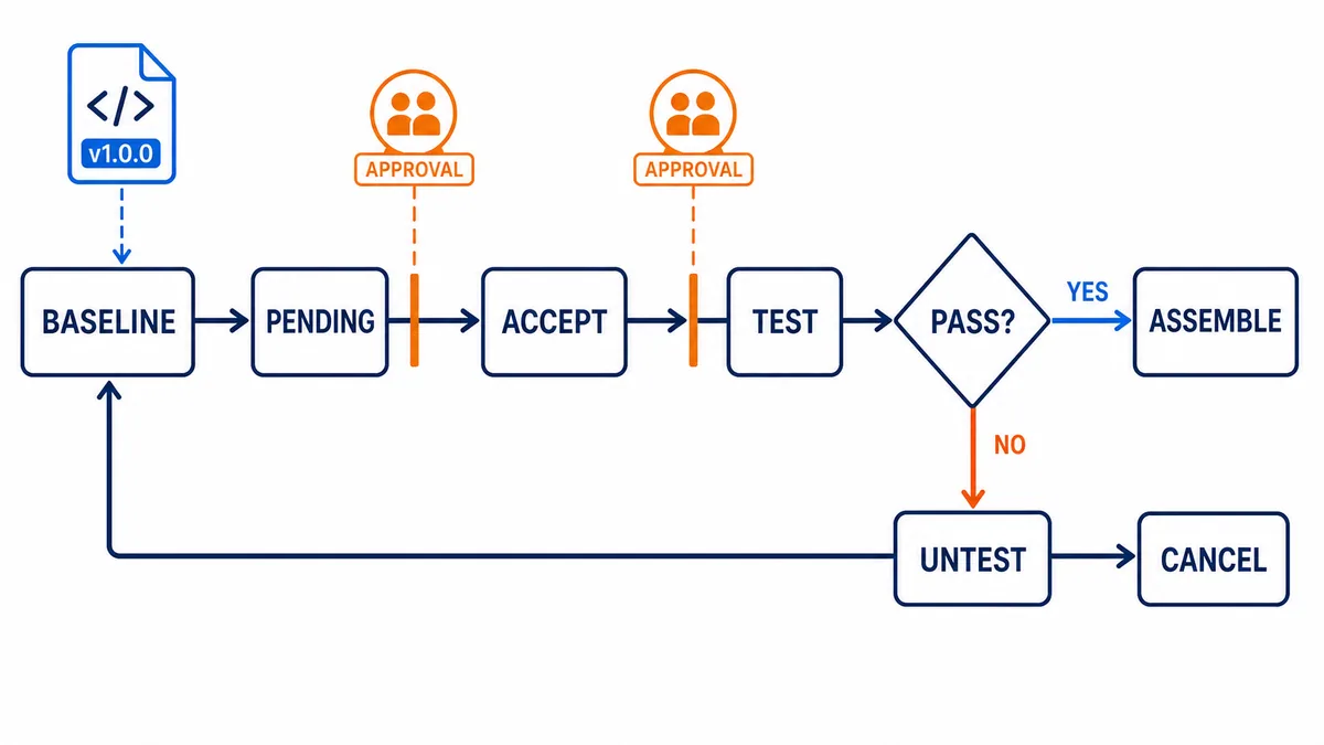
| Change state | What is executing | Decision evidence |
|---|---|---|
| baseline | known original routine | approved as-found project and operating state captured |
| pending | original logic | edit verified and reviewed locally; no controller execution change yet |
| accepted, not tested | original edit zones | controller contains accepted zones, but test logic is not yet executing |
| test edits | inserted/test zones plus unaffected regular logic | controlled observations match acceptance cases and no unsafe/unexpected state |
| untest | original edit zones again | failed/aborted test returned to original execution before cancel |
| assembled | tested edit becomes regular logic | final verification, as-left archive, change record and monitoring complete |
Online capability is not permission. Forces, output commands, firmware changes, mode changes and online edits can move equipment or disable intended behavior. Follow the site change process, hazardous-energy program and electrical safe-work rules; use qualified, authorized personnel.
Troubleshoot Allen-Bradley PLCs with an evidence funnel
Start above the rung
When a machine stops, do not begin by editing the highlighted rung. First establish whether the controller is powered, in the expected mode and running its task; whether a major fault stopped execution; whether an I/O or network connection failed; and whether the project on the workstation actually matches the controller.
Use the dedicated Allen-Bradley PLC troubleshooting and diagnosis guide for the complete nine-step field workflow, including as-found incident capture, Studio 5000 module faults, raw-versus-mapped tag tracing, intermittent evidence packets and controlled recovery.
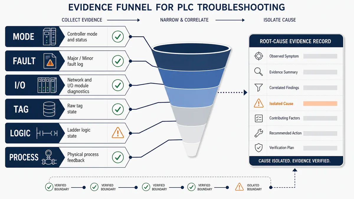
Correlate six diagnostic boundaries
| Boundary | Evidence | If evidence disagrees |
|---|---|---|
| mode/execution | controller status, mode, task state/watchdog and matching online project | resolve identity, fault or task scheduling before editing logic |
| major/minor fault | fault type/code, timestamp/context, faulted task/program/routine and recurrence | preserve record; identify invalid operation or resource condition before clearing |
| I/O/network | module tree warning, connection state, exact fault code, keying, path and device diagnostics | isolate configuration, power, cabling, address, profile or device fault |
| raw/module tag | input/output/status member and quality/connection | compare actual field state and module data contract |
| alias/application tag | alias target, buffer/mapping routine, cross-reference and writers | correct mapping, scheduling or duplicate ownership |
| logic/process | rung conditions, command, feedback, permissive reason and physical observation | distinguish intended inhibit from code defect, field fault or process condition |
Rockwell’s fault manual distinguishes major, minor and I/O faults. A major fault can stop logic; a minor fault records a condition without necessarily stopping execution; an I/O fault points to connection/configuration issues and displays codes and module warnings. Clearing a fault without preserving its type/code, location and triggering data destroys useful evidence.
Diagnose common symptoms without guessing
| Symptom | First discriminating checks | Common root-cause surfaces | Avoid |
|---|---|---|---|
| cannot go online | controller identity/firmware, network path, workstation IP/driver and project match | wrong controller/path, incompatible version, routing or security | selecting download merely to make the dialog disappear |
| project will not open | file type, project revision and installed Logix Designer versions | missing major version, corrupt/untrusted archive or wrong software family | converting the only source copy |
| controller major faulted | exact fault code/type, task/program/routine and fault log | watchdog, invalid array/indirect address, arithmetic/data or application defect | clear-and-run loops without cause containment |
| I/O tree yellow warning | module connection code, keying, catalogue/revision, power and network | wrong device/revision, inhibited/failed connection, timeout or module fault | disabling keying without engineering review |
| field input LED on, tag off | exact module channel/status member, raw tag, alias target and connection | wrong tag/slot/member, mapping issue, stale connection or wiring boundary | rewriting application logic first |
| raw tag changes, logic does not | task/program/routine execution, JSR/main routine, buffer timing and condition | routine not scheduled/called, wrong scope, conditional call or stale buffer | forcing the application tag |
| rung true, output off | final writers, output mapping, interlock/mode arbitration, module tag/status | duplicate coil, downstream owner, output fault or no load supply | treating green rung highlight as physical proof |
| intermittent sequence | trend timestamps, task timing, state transition reasons and comms quality | race, missed transient, asynchronous data, chatter or process feedback | adding delays until symptom disappears |
For intermittent faults, collect a bounded incident packet: UTC/local timestamp, controller clock relation, mode, fault and module state, relevant raw and application tags, sequence state, task metrics, HMI alarm, network/device diagnostics and physical process evidence. The intermittent PLC fault troubleshooting guide expands that method; the EtherNet/IP PLC guide covers cyclic connections and network evidence.
Review, test and commission for maintainability
Use a programming review matrix
| Review gate | Questions | Pass evidence |
|---|---|---|
| compatibility | exact controller, firmware, software build, profiles and workstation supported? | dated PCDC/manufacturer evidence and tested engineering station |
| structure | tasks/programs/routines reflect functional ownership and timing? | architecture map, scheduler data and cross-reference |
| data | tags typed, scoped, initialized and owned; I/O quality preserved? | tag dictionary, writer list and interface contract |
| behavior | normal, boundary, fault, abort, recovery and restart requirements implemented? | requirements-to-test traceability |
| diagnostics | operator/maintainer can see why a command is inhibited or failed? | reason bits, alarm context and timestamps |
| changes | upload/download/online edit/force policy and rollback defined? | approved method, backups, compare and as-left archive |
| security | workstation, accounts, project files and network access controlled? | role/access record and protected source workflow |
| safety | safety functions remain in validated safety lifecycle and hardware? | safety requirements, signature/validation and independent approval |
Preserve an as-left evidence package
The finished work product is more than an ACD file. Retain the exact exported project/archive, project revision and checksum, controller and module catalogue/firmware inventory, installed software/build/profile list, network path and addressing, drawings and I/O list, cause-and-effect requirements, test results, fault/forcing status, change approvals, unresolved deviations and recovery instructions.
Record whether forces exist and whether they are enabled. A force indicator is not a reason to remove forces blindly: first identify why each force exists and what equipment state will result when it is disabled or removed. Use the same care for inhibited modules, overridden commands, temporary jumpers and maintenance-mode bits.
Diagnostic answer map for search and AI-assisted troubleshooting
| User or AI query | Concise answer | Qualification that must travel with it |
|---|---|---|
| What software programs Allen-Bradley PLCs? | Studio 5000 Logix Designer programs modern CompactLogix/ControlLogix; CCW programs Micro800; RSLogix 500 serves many SLC/MicroLogix systems. | Identify exact catalogue and firmware; other legacy families differ. |
| Is RSLogix 5000 the same as Studio 5000? | Logix Designer is the programming application now within Studio 5000; “RSLogix 5000” is the older product name commonly used for earlier revisions. | Match the actual project/controller major revision. |
| How do I start Allen-Bradley PLC programming? | Select the correct family/software, create the exact controller project, configure I/O, define tags, organize tasks/programs/routines, verify and test. | Do offline/isolated tests before authorized commissioning. |
| What are tasks, programs and routines? | Tasks schedule; programs group data and routines; routines contain executable code. | A routine executes only when scheduled as main or called. |
| Why can I not go online with a CompactLogix? | Common boundaries are wrong path/controller, firmware/software mismatch, network/security or an offline project mismatch. | Do not download until identity and consequence are proven. |
| What is the difference between upload and download? | Upload reads controller project to workstation; download writes workstation project to controller. | Download can change running behavior/mode and requires control. |
| How do I find an Allen-Bradley PLC fault? | Capture mode and exact major/minor/I/O code, task/program/routine or module location, then correlate tags, logic and process. | Preserve evidence before clearing or cycling power. |
| Can I simulate Studio 5000 ladder logic? | Supported Rockwell emulation can test scoped Logix behavior; browser tools can teach concepts. | Neither proves field wiring, safety or full machine behavior. |
| Can I edit Allen-Bradley logic while running? | Supported Logix projects allow controlled pending, accepted, test and assembled online-edit states. | Capability is not permission; use approved change and rollback controls. |
| Why is my output rung true but output off? | Check the final writer, mapping/arbitration, module output tag/status, electrical load power and feedback. | Rung highlight is not proof of physical energization. |
Frequently asked questions
Which Allen-Bradley PLC is best for learning?
Choose by the environment you need to learn. Micro800 with CCW offers an accessible current Rockwell micro-controller path; CompactLogix introduces the Logix 5000 tag/task model used with Studio 5000. If your workplace has an existing platform, match that exact family while keeping training isolated from production.
Is Connected Components Workbench the same as Studio 5000?
No. CCW is the programming and device-configuration environment for Micro800 and connected-components products. Studio 5000 Logix Designer serves Logix 5000 controller families such as CompactLogix and ControlLogix. Their project models and files are not interchangeable.
Do I need the same Studio 5000 version as the PLC firmware?
For Logix systems, the controller firmware and Logix Designer application must match at the major revision level. Exact minor build and supporting software compatibility still require the controller documentation and PCDC review.
What programming languages do Allen-Bradley PLCs use?
Language support depends on controller and software. Current Logix platforms can support ladder diagram, structured text, function block diagram and sequential function chart according to controller/project features. Micro800 uses supported IEC languages through CCW. Verify the exact product and edition.
What is an ACD file?
ACD is the native project file used by Studio 5000 Logix Designer. Treat it as controlled engineering source: record its software revision, provenance, checksum and matching controller state. It does not contain every external device, HMI, safety or validation artifact needed to recover a system.
Why is my Allen-Bradley routine not running?
A routine may exist without execution. Confirm its program is scheduled in an active task, it is configured as the program main routine or reached by an executing JSR, and conditional calls or task states are not excluding it. Then check the online project match.
Can multiple rungs write the same output tag?
The software may allow several writers, but final state then depends on execution order and indirect writes, making behavior hard to reason about. Prefer one documented final owner that arbitrates commands, modes and interlocks, and use cross-reference to prove it.
Does uploading from a PLC change its program?
An ordinary upload reads controller-resident project content toward the workstation rather than downloading a project into the controller. Connecting, selecting paths and related workflows still require correct identity and authorization; preserve the resulting file as observed evidence, not automatically approved source.
Can I clear a major fault and restart the PLC?
Only after capturing the exact fault and proving the cause, consequence and safe restart state. A recoverable fault can recur immediately or expose an application defect. Follow the controller manual and site recovery/change process; do not repeatedly clear-and-run.
Is an Allen-Bradley simulator enough for commissioning?
No. Simulation can support logic tests within its documented scope. Commissioning must also prove the exact firmware, I/O, network, electrical interfaces, field devices, process response, alarms, restart behavior and required safety functions on approved equipment and under controlled conditions.
Sources, review scope, and limitations
This guide was reviewed on August 28, 2026 against the sources below. Rockwell software, firmware, manuals, controller support and compatibility matrices change. Verify the exact installed controller, safety partner, modules, firmware, software build, profiles, activation and project before use.
- Studio 5000 Logix Designer v38 Online Help — Rockwell Automation
- Controller firmware and Logix Designer application compatibility — Rockwell Automation
- Logix 5000 Controllers Common Procedures, 1756-PM001 — Rockwell Automation
- Logix 5000 Controllers Tasks, Programs, and Routines, 1756-PM005 — Rockwell Automation
- Logix 5000 Controllers I/O and Tag Data, 1756-PM004 — Rockwell Automation
- Logix 5000 Controllers Ladder Diagram, 1756-PM008 — Rockwell Automation
- Logix 5000 Controllers Major, Minor, and I/O Faults, 1756-PM014 — Rockwell Automation
- Logix 5000 Controllers Design Considerations, 1756-RM094 — Rockwell Automation
- Edit ladder logic in Run mode, Studio 5000 v38 help — Rockwell Automation
- Upload a project from an online controller, Studio 5000 v38 help — Rockwell Automation
- Micro800 Controller Family Selection Guide, 2080-SG001 — Rockwell Automation
- Connected Components Workbench tutorials and Micro800 simulator scope — Rockwell Automation
- 29 CFR 1910.147, control of hazardous energy — OSHA
- 29 CFR 1910.333, electrical work practices — OSHA
The figures are conceptual editorial illustrations, not Rockwell software screenshots, product-selection drawings, electrical schematics, safety designs or field procedures. Product images are not guaranteed to match a specific catalogue. This page does not authorize connecting to a controller, going online, downloading/uploading, flashing firmware, changing mode, accepting/testing/assembling edits, clearing faults, forcing I/O, inhibiting modules, bypassing logic or energizing equipment. Only qualified, authorized personnel following the site risk assessment, hazardous-energy and electrical safe-work programs, validated safety lifecycle, approved change plan, exact manufacturer documentation and engineered recovery method should modify or test an installed control system.
Now run it · free to start
Learn a repeatable way to find the fault
Split a stopped machine into input, logic, output and physical response, and take the measurement that proves each stage. Practised on simulated machines. Free to start.
Ownership disclosure: PLC Programming IO and PLC Simulation Software are operated by the same publisher.
PLC Programming IO Editorial Team
Industrial automation education, references, and software testing
The PLC Programming IO Editorial Team publishes sourced industrial-automation education and documents how material is reviewed, tested, and corrected. A team byline means the publisher is responsible for the page; it does not represent a fictional person or imply an engineering licence.
Coverage:
- • PLC programming concepts and examples
- • Vendor software tutorials and comparisons
- • SCADA, HMI, protocols, and instrumentation
- • Training, careers, and reference material
Review standard:
- • Prefer primary and official sources
- • Record software versions when material
- • Separate tested facts from estimates
- • Publish material corrections
Important scope note
This site provides education, not project-specific engineering approval. Safety, code, and compliance decisions require a qualified person with access to the actual machine and jurisdiction.