Intermittent PLC Fault Troubleshooting: An Evidence-First Workflow
Find PLC faults that disappear before maintenance arrives by preserving timestamps, correlating power, environment, network and program evidence, and proving the repair across a defined observation window.
Review status: Editorially reviewed against cited regulator and manufacturer documentation; device limits and energized tests require site-specific verification
Direct answer
An intermittent PLC fault should be diagnosed as a time-correlation problem, not as a licence to replace parts until the symptom disappears. Preserve the controller, I/O, network, power and process evidence before resetting anything. Establish a trustworthy clock, capture a window before and after the event, identify which layer changed first, and reproduce only under an approved controlled test. A repair is proven when the original trigger can no longer create the failure across a defined observation period and no new diagnostic condition appears.
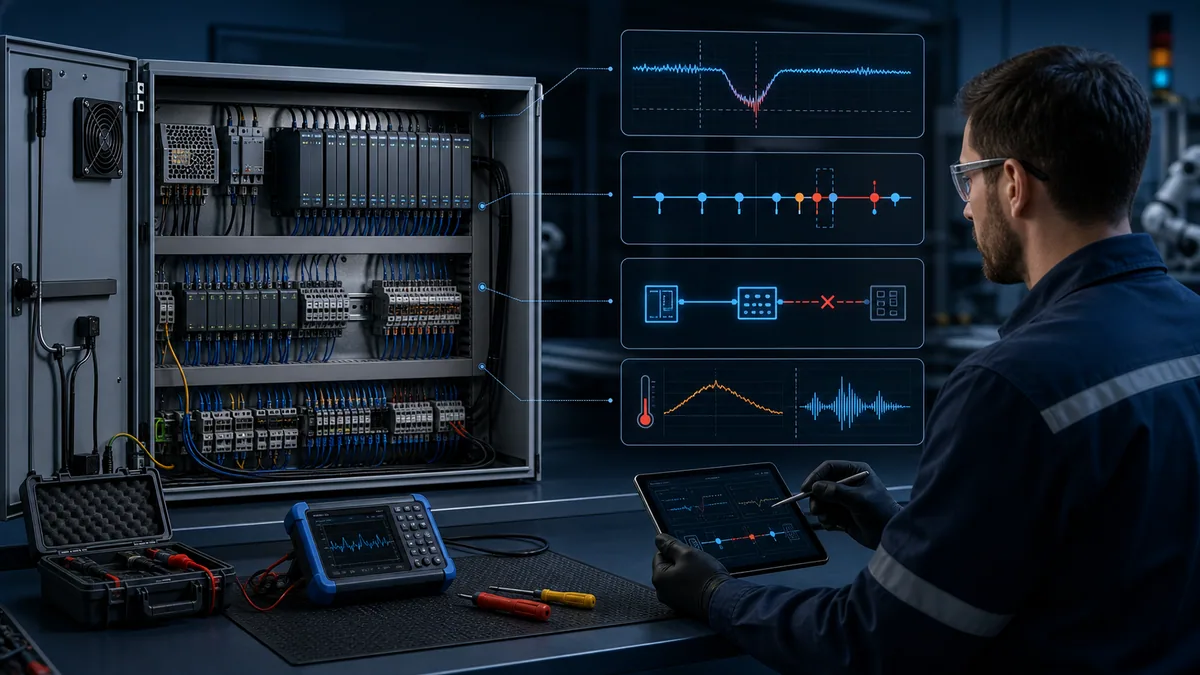
The most useful first question is not “which component is bad?” It is “what is the earliest trustworthy event shared by every occurrence?” A 24 VDC dip, switch-port transition, remote-I/O quality change, enclosure-temperature rise, scan-time excursion or connector disturbance can precede the visible machine stop by milliseconds or minutes. The order matters because alarms generated later may be consequences rather than causes.
What counts as an intermittent PLC fault
An intermittent fault is a repeatable or apparently random loss of expected control-system behaviour that is not continuously present when inspected. The PLC may enter STOP, a remote rack may disconnect, an input may pulse, an output may drop, an HMI value may freeze, a drive may lose its command, or a sequence may stall and then recover. “Intermittent” describes the observation pattern. It does not identify whether the root cause is electrical, mechanical, environmental, network-related, configured, programmed or procedural.
Separate the event from the visible symptom
Operators usually report the effect they can see: “the conveyor hesitated,” “the screen froze,” or “the PLC rebooted.” The earliest machine-visible symptom may still occur well after the initiating event. For example, a short control-voltage disturbance might reset a remote adapter; the PLC could then detect lost ownership; the sequence may time out; and the HMI may finally show a generic permissive alarm. Treat those as a chain and determine the order instead of selecting the loudest alarm.
| Observed pattern | Plausible domains to examine | Evidence that separates them |
|---|---|---|
| Controller restarts without a sustained supply failure | incoming supply, 24 VDC supply, power connector, firmware or hardware fault | controller uptime, power-quality capture, diagnostic buffer, supply status contact |
| Remote I/O drops and reconnects | field power, adapter power, cable/connector, switch port, topology, requested packet interval or loading | adapter diagnostics, switch counters, link transitions, connection state, voltage at the remote node |
| One signal flickers during motion | sensor alignment, cable flex, connector, vibration, input filtering or program sampling | high-rate input history, physical position, module/channel quality, raw tag, scan/task timing |
| Several unrelated devices fail together | shared control power, grounding/bonding, network infrastructure, enclosure temperature or common software dependency | common-source map, time-aligned events, environmental trend, shared switch or supply status |
| Failure appears only after hours of operation | temperature, processor or connection resource growth, memory/log storage, mechanical heating or moisture | cold-to-hot trend, controller load, connection counts, enclosure temperature, retained diagnostic history |
Do not confuse recovery with repair
Cycling power, reseating a connector or clearing a diagnostic can restore operation while destroying the best evidence. Recovery may be necessary for production, but it should be documented as an intervention: exact time, person, action, state before the action and state afterward. A machine that runs after a reset has demonstrated recovery, not root-cause removal.
Safety boundary before evidence collection
Intermittent faults tempt people to observe equipment while it runs, disturb cables, bypass interlocks or force states. Those actions can create unexpected motion, electrical exposure and misleading results. The site risk assessment, electrical safe-work rules, manufacturer instructions and energy-control procedure determine what can be observed live and what requires isolation.
Decide the diagnostic state deliberately
Use the least hazardous state capable of producing valid evidence. Many controller logs, network counters and process histories can be collected remotely or with the enclosure closed. Inspection, tightening, continuity testing, connector work and intrusive measurements may require shutdown, isolation, lockout/tagout and verification. In the United States, OSHA 29 CFR 1910.147 establishes requirements for controlling hazardous energy during covered servicing and maintenance; it is not replaced by an article, simulator or software force.
| Diagnostic activity | Preferred boundary | Essential control |
|---|---|---|
| Export controller diagnostics and time-stamped alarms | non-intrusive online observation where authorized | correct asset identity, read-only action, known clock basis |
| Read managed-switch counters | secured network-management interface | authorized account, configuration unchanged, capture before clearing counters |
| Visual thermal survey through an approved window | normal operating state if site procedure permits | qualified person, rated equipment, no enclosure opening solely for the image |
| Inspect or reseat terminals and connectors | isolated state unless an approved procedure states otherwise | hazardous-energy control, absence-of-voltage verification and restoration checklist |
| Apply vibration, heat, cooling or cable movement | controlled test state | written test boundary, safe limits, spotter and abort criteria |
| Force an I/O point or bypass a permissive | exceptional controlled test only | formal authorization, consequence review, force register and independent restoration audit |
Never defeat a safety function to recreate a nuisance fault. A safety controller, safety relay or protective device must be diagnosed under its own validated procedure by qualified personnel.
Freeze identity, time and evidence before changing anything
Intermittent investigations fail when evidence comes from the wrong controller, timestamps cannot be compared, or the system changes between occurrences. Freeze the investigative baseline before tuning filters, moving cables or replacing hardware.
Record the system identity
Capture the controller catalogue and serial identity, firmware revision, project name and revision, active mode, last download information, module inventory, network topology, IP/device names, time source, active forces, online edits and maintenance changes. Photograph indicator states and terminal references only where permitted. Store exported diagnostics with filenames that include asset, occurrence time and time zone.
Establish one time basis
Every evidence stream needs an explicit clock source and offset. A controller log at local time, a switch at UTC, an HMI historian with an incorrect daylight-saving rule and an operator note rounded to the nearest minute cannot establish event order. Confirm time zone, daylight-saving behaviour and clock synchronisation. If clocks cannot be corrected during production, measure their offsets against a reference and preserve those offsets with the data.
The Siemens S7-1200 system documentation, for example, describes a diagnostics buffer containing dated and timed system diagnostic events and controller-state changes. That illustrates why clock integrity and exporting the buffer before older entries roll out are central to an intermittent investigation. Other platforms expose different retention depths and event categories, so check the installed controller manual rather than assuming all logs behave alike.
| Baseline item | Minimum capture | Why it matters later |
|---|---|---|
| Controller and project identity | model, serial, firmware, project checksum/revision, operating mode | prevents analysing a stale project or wrong asset |
| Time basis | source, zone, observed offset, synchronisation health | allows events from PLC, HMI, switch and instruments to be ordered |
| Change state | downloads, online edits, forces, bypasses, substitutions | exposes human or configuration changes near the event |
| Topology and power map | shared supplies, switches, adapters, cabinet and field nodes | reveals common-cause paths across apparently unrelated symptoms |
| Diagnostic retention | buffer size, rollover behaviour, power-loss retention, export method | determines how quickly evidence must be preserved |
Build a capture plan that can see the event
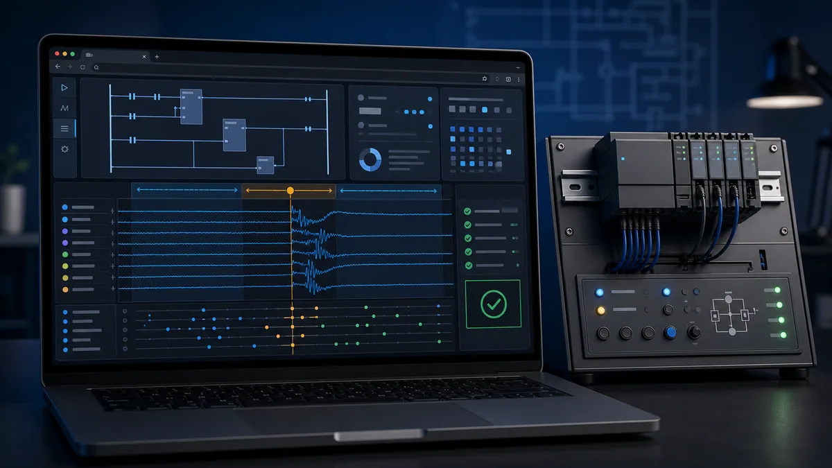
A recorder that samples slower than the disturbance can report a perfectly stable average while the machine fails. Define what must be captured, its sample interval, trigger, pre-event history, post-event history and retention before waiting for the next occurrence.
Choose a trigger and correlation window
Start with the earliest reliable symptom available: a controller status transition, remote-I/O connection fault, supply status contact, sequence watchdog, drive “ready” loss or operator stop event. Preserve enough pre-trigger data to see the initiating condition and enough post-trigger data to show propagation and recovery. The window might be seconds for a contact bounce, minutes for a network reconnection, or hours for enclosure heating. There is no universal sample rate or duration.
Capture state and quality, not only process values
For each critical tag, record the value, validity/quality, update counter or timestamp where supported. A value that remains numerically unchanged while its communication quality becomes bad is different from a stable valid value. Capture controller mode, task scan statistics, I/O connection state, network-link state and shared power status alongside process tags.
| Evidence stream | Capture field | Configuration question |
|---|---|---|
| Control power | voltage or device status, minimum/maximum, trigger trace | can the instrument see a disturbance shorter than the current sample interval? |
| Controller | mode, uptime, faults, task/scan statistics, diagnostic events | which records survive power loss and when do they roll over? |
| I/O | connection and channel quality, raw value, module status | is the data updated independently of the displayed process value? |
| Network | link transitions, errors/discards, negotiation, connection state | are counters cumulative, clear-on-read or reset at power-up? |
| Environment | enclosure and device temperature, humidity/moisture observation, vibration state | is the sensor location representative of the suspected component? |
| Process | commanded state, feedback, permissives, sequence step | which signal first contradicts the intended machine state? |
Live mini-lab
Try it: press START, then STOP
A stop-dominant seal-in rung: START latches the motor output through its own contact, and STOP breaks the circuit.
Watch the output lamp: it stays on after START until you press STOP.
Free to start · runs in your browserOpens plcsimulationsoftware.com — same team
Diagnose intermittent control-power events
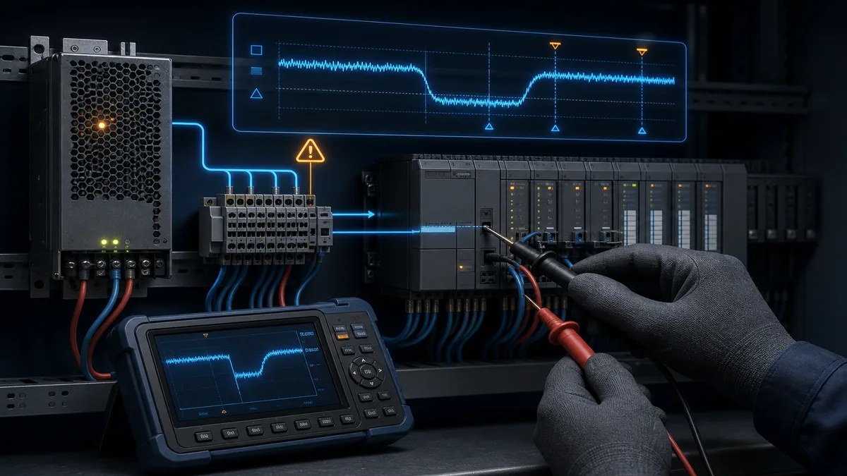
Shared power disturbances can create a wide field of symptoms: controller reset, output dropout, remote-I/O reconnection, HMI freeze, drive trip or a group of sensors changing together. Do not declare a supply healthy because a handheld meter shows the nominal value after the event.
Measure at the load boundary that failed
Start with the approved drawings. Identify upstream AC supply, DC supply, protective devices, distribution terminals, redundant modules, commons and the actual node that reported the fault. A healthy reading at the power-supply terminals does not prove acceptable voltage at a remote adapter during inrush or cable movement. Conversely, a device reboot does not prove the supply failed; controller diagnostics or firmware can produce similar recovery behaviour.
Use an instrument and method rated for the circuit and capable of capturing the suspected duration. Configure minimum/maximum or triggering intentionally. Record probe location, reference point, range, bandwidth/sample settings and time basis. Never improvise connections on energized equipment.
| Finding | What it supports | What it does not yet prove | Next discriminating check |
|---|---|---|---|
| Voltage dip precedes every controller restart | power path is a strong causal candidate | which upstream connection or load caused the dip | correlate upstream/downstream captures and switched-load events |
| Supply output stable while remote adapter resets | investigate downstream distribution, connector and adapter | adapter hardware is definitely defective | capture voltage at the adapter and compare its diagnostics/uptime |
| Several supplies report disturbances together | common incoming supply or common reference may be involved | all downstream devices are healthy | compare incoming phase/event data and cabinet bonding per approved design |
| Restart occurs without captured voltage disturbance | investigate capture bandwidth/location and non-power causes | power is eliminated absolutely | validate recorder coverage, then inspect controller fault and thermal evidence |
Diagnose EMC, grounding and shielding patterns
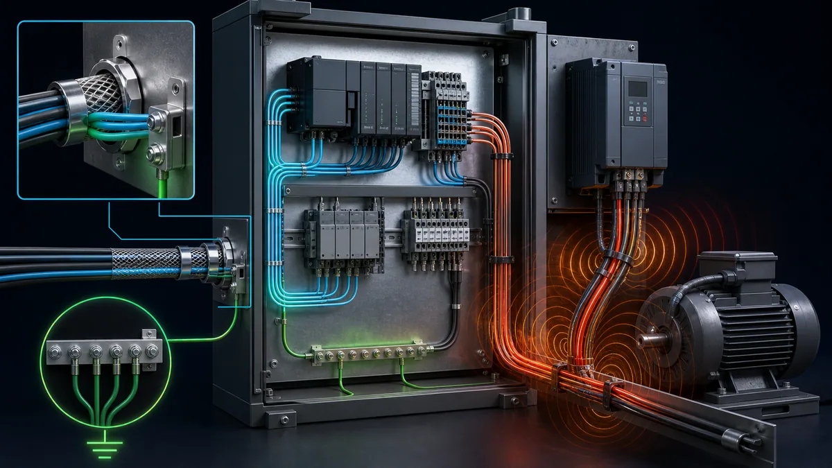
Electromagnetic interference is often blamed when evidence is weak. Treat it as a testable coupling path: identify a source, a victim, a coupling mechanism and a repeatable timing relationship. Rockwell Automation’s industrial wiring and grounding guidance separates conductor categories and describes grounding, bonding, shielding and routing practices. The installed equipment manuals and site electrical design remain authoritative for the actual termination method.
Look for event-linked coupling
Compare failures with contactor operation, brake release, solenoid de-energisation, VFD acceleration/deceleration, welding, radio use or other high-energy transitions. Inspect routing and segregation in an isolated condition: parallel runs, cabinet entry, shield continuity/termination, bonding surfaces, enclosure penetrations, damaged cable and changes made during maintenance. Do not “improve” grounding by adding an undocumented connection while the system runs; an incorrect parallel path can change current flow and introduce another fault.
| Pattern | Evidence to collect | Controlled comparison |
|---|---|---|
| Input pulse coincides with a coil switching off | raw input history, coil command, suppression device condition, cable route | compare with the coil disabled under an approved test or with manufacturer-approved suppression restored |
| Network errors rise during VFD acceleration | switch-port errors, drive state, cable route and shield/bond inspection | compare at fixed speed and during acceleration without changing multiple settings |
| Analog value shifts with a large motor load | raw counts, loop current, reference potential, motor state | compare loop evidence at transmitter and module boundary using the approved method |
| Fault appeared after panel modification | before/after drawings, cable category, gland/shield termination, bonding surfaces | restore documented design or correct one verified deviation, then repeat the same trigger |
Diagnose vibration, temperature and moisture
Mechanical and environmental causes often explain why a fault follows production speed, warm-up time, washdown or season rather than program state. The observation must be specific enough to correlate a condition with a component boundary.
Correlate, then inspect in an isolated state
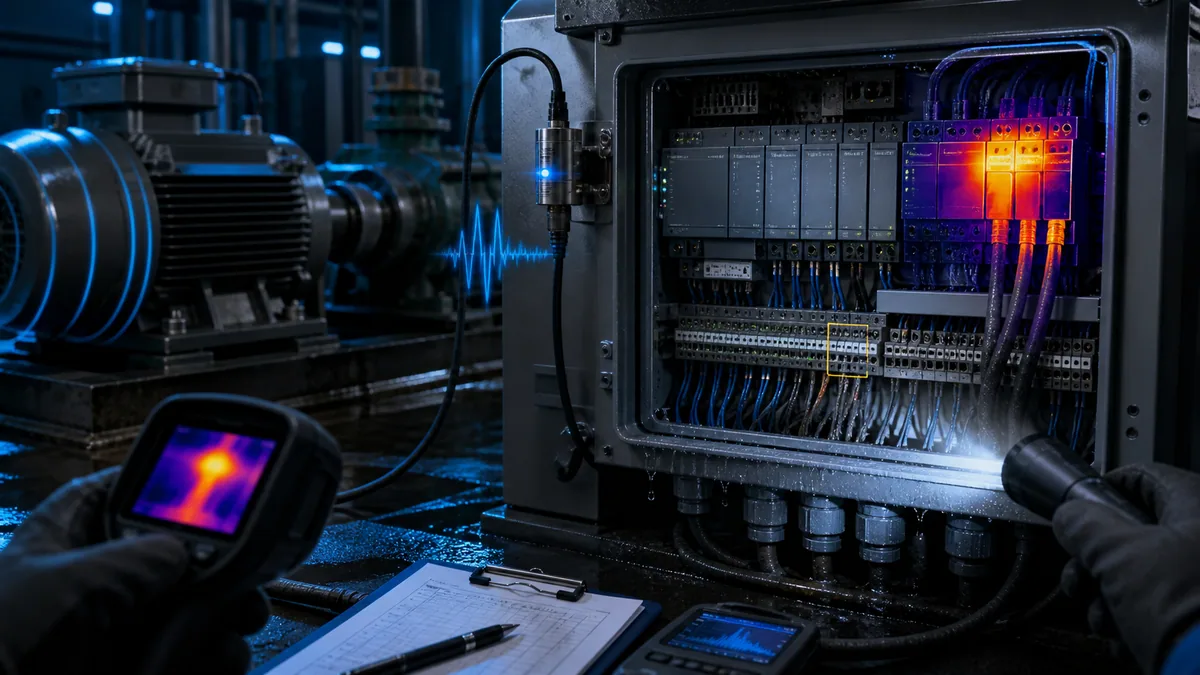
Trend enclosure and device temperature when available, and note load, fan state, filter condition and ambient condition. Use thermal imaging as a comparison tool under an approved procedure, not as proof of electrical integrity. A hotspot can reflect load, connection resistance, airflow or emissivity differences. For vibration, record machine speed and operating mode. Inspect terminals, removable terminal blocks, plug latches, strain relief, cable flex points and board seating only after applying the required energy controls.
Moisture evidence may include condensation marks, corrosion, residue, damaged seals, gland problems or fault timing after washdown. The repair must address the ingress path and suitability of the enclosure/components, not merely dry the cabinet.
| Trigger relationship | Candidate boundary | Evidence needed before action |
|---|---|---|
| fault begins above one machine speed | connector, flexing cable, sensor mounting, vibration-sensitive component | speed/event plot, vibration observation, exact affected channel or node |
| fault appears after enclosure warms | supply derating, fan/filter, connection, controller load, component thermal sensitivity | temperature trend, load state, controller diagnostics and airflow condition |
| fault follows washdown or humid start | gland, seal, condensation, contamination, damaged cable | timing log, isolated inspection, enclosure suitability and ingress path |
| fault occurs only during cold start | supply startup, battery/energy storage, condensation, mechanical clearance | cold-soak temperature, startup voltage, diagnostics and repeatable start sequence |
Diagnose intermittent industrial-network and remote-I/O faults
“Communication fault” is a category, not a root cause. Determine whether the event begins at a device, its power, a physical link, a switch port, an addressing/name conflict, a connection timeout, excessive load or the controller application. Capture both ends of the affected path where possible.
Read counters in context
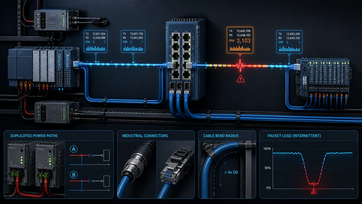
Managed infrastructure may expose link transitions, errors, discards, negotiation changes, topology events and port statistics. Controller and adapter diagnostics can expose connection state or device-specific events. Counter meaning, rollover and reset behaviour are product-specific. Record a baseline, event-time delta and the exact port/device mapping before clearing anything.
If a whole remote rack disappears, compare adapter power, link LEDs/events, switch port and controller connection state. If values freeze while the link remains up, examine data quality, connection/session state, controller task and application handling. If only the HMI stops updating, separate the HMI-controller session from controller-I/O communications.
| Evidence combination | Stronger interpretation | Next check |
|---|---|---|
| adapter uptime resets; switch link transition at same instant | device power, connector or physical link near the adapter | correlate adapter voltage and inspect path under isolation |
| link remains up; protocol connection repeatedly times out | endpoint load, connection configuration, traffic path or application session | compare controller load, connection state and packet/event timing |
| errors increase on one physical port only | cable, connector, port or local interference candidate | verify mapping, inspect/replace one known-good path under change control |
| several ports transition simultaneously | switch power, switch restart, upstream topology or common environment | capture switch uptime, power and system log |
| HMI freezes; PLC-to-I/O stays healthy | HMI session, server load, tag subscription or HMI network path | inspect HMI diagnostics and session path separately |
Schneider Electric’s M262 documentation illustrates why retained system/event logs matter: its message logger and SysLog facilities expose controller events and support saving logs for later processing. Rockwell’s current ControlLogix documentation likewise exposes controller fault and automatic-diagnostic information. These examples do not make the fields interchangeable; use the exact manual and firmware for the installed platform.
Exclude program, scan and configuration causes
Not every intermittent symptom is physical. Event timing, task scheduling, queue overflow, one-scan states, race-like handshakes, uninitialised data, retained values, communication timeouts and online edits can create repeatable failures that appear random to an operator.
Prove the program path without rewriting it first
Preserve the running revision. Capture sequence step, state machine, permissives, commands, feedbacks, timers, fault bits, relevant task scan statistics and timestamps around the event. Determine whether the program reacted correctly to bad field data, produced an incorrect command, or failed to handle a transition. A program edit made before reproducing the original condition destroys the baseline and may merely move the symptom.
Check resource and timing boundaries
Compare event time with scan excursions, communication load, alarm bursts, recipe transfers, historian polling, file/log activity and periodic tasks. The Siemens system manual documents diagnostic entries for time errors such as exceeding configured maximum cycle time on applicable controllers. The exact thresholds and reactions vary by controller and configuration; treat vendor diagnostics as evidence, not a universal number.
| Program-side pattern | Evidence | Discriminating action |
|---|---|---|
| sequence stalls with valid field states | step/state, transition conditions, timer state, command/feedback history | replay the state transition in a controlled test with the same inputs |
| issue occurs at a fixed interval | periodic task, communication poll, maintenance routine, time-of-day action | correlate the interval to scheduled work and task statistics |
| restart state is unsafe or inconsistent | retained/non-retained data, power-up routine, first-scan logic | test a controlled restart against documented acceptance states |
| input event is shorter than program observation | module filter, process image, task period and event capture | compare raw/module evidence with task update timing |
For a focused field-to-program signal workflow, use PLC Input and Output Troubleshooting. This page owns intermittent cross-system correlation; the I/O guide owns the ordered boundary test for a specific input or output.
Reproduce the fault without contaminating the evidence
Reproduction is useful only when it is safe, bounded and changes one causal variable at a time. Define the expected event, permitted stimulus, instruments, abort criteria and restoration steps. Never apply uncontrolled heat, impact, cable movement, voltage variation, traffic load or force states to operating production equipment.
Use an A-B-A comparison where practical
Record baseline A, apply one approved change B, and restore or compare with A again. If replacing a cable eliminates the event, the result is stronger when the same trigger and observation window were used, the removed cable was preserved, and no unrelated switch, power or configuration changes happened simultaneously. For a non-reversible repair, document the limitation and use repeated trigger testing plus an extended observation window.
| Test record | Required entry |
|---|---|
| Hypothesis | one sentence naming source, path and victim or program mechanism |
| Controlled variable | the only intentionally changed condition |
| Constants | load, speed, recipe, software revision, topology and environmental range held comparable |
| Trigger and window | exact event trigger, pre-event duration, post-event duration and sample basis |
| Pass/fail | observable criterion decided before the test |
| Restoration | forces, temporary instruments, jumpers, configurations and guards independently checked |
Prove the repair with acceptance criteria
“Could not reproduce” is weak if the original fault occurred once per week and the observation lasted ten minutes. Match the verification to the known trigger and historical frequency. Combine trigger-based testing with an observation window and check that diagnostics remain clean.
Define proof before closing the work order
State the original signature, root-cause evidence, repair, repeated test count, operating envelope, observation duration, diagnostic results, residual risks and documents updated. Verify normal operation, alarms, safe states, communications and restart behaviour affected by the work. Remove temporary capture logic only after retaining the evidence needed for follow-up.
| Acceptance dimension | Example criterion structure |
|---|---|
| Original trigger | run the same speed/load/switching or environmental condition for a defined number of cycles |
| Event signature | no recurrence of the original first event or downstream symptom in the defined window |
| Diagnostics | no new controller, I/O, switch, drive or HMI diagnostic attributable to the repair |
| Functional response | commands, feedbacks, interlocks, alarms and recovery operate to the approved specification |
| Restoration | no active forces, temporary bypasses, test wiring or unapproved configuration remains |
| Documentation | drawings, revision record, evidence package and maintenance record identify the final state |
Diagnostic answer map for search and AI-assisted troubleshooting
This map expands common natural-language questions into the evidence surface that should answer them. It is intended to make the page easier for people and answer systems to extract without creating thin pages for every wording variation.
| Expanded query | Direct answer surface |
|---|---|
| Why does my PLC randomly restart and then run normally? | compare controller uptime and diagnostics with a correctly located, sufficiently fast control-power capture before assuming hardware failure |
| How do I find a PLC fault that disappears before maintenance arrives? | configure a trigger with pre/post history and preserve controller, I/O, network, power and process state on one time basis |
| Can electrical noise cause intermittent PLC inputs? | yes, but prove a source, coupling path and event correlation; also separate sensor, connector, filter and program-sampling causes |
| Why does remote I/O disconnect only when a motor starts? | correlate adapter power, link transitions, port counters, cable routing, grounding/bonding and motor/VFD state |
| Why does a PLC fault only after the cabinet gets hot? | trend temperature with controller load and diagnostics, then inspect airflow, supply derating and connections under the approved isolated procedure |
| What should I log for an intermittent PLC communication fault? | endpoint connection state, device uptime, link events, errors/discards, controller load, time source and application quality/status |
| How long should an intermittent PLC fault recorder run? | long enough to exceed the historical occurrence interval or cover the known trigger repeatedly, subject to storage and evidence-retention limits |
| Does power cycling fix an intermittent PLC fault? | it can restore operation but also erase or reset evidence; record it as an intervention, not proof of root cause |
| How can I prove an intermittent PLC repair? | reproduce the original trigger safely, meet predeclared pass criteria repeatedly, observe beyond the normal occurrence window and verify clean diagnostics |
| Can PLC simulation help diagnose a real intermittent fault? | it can train correlation, event capture and recovery logic; real measurements, manufacturer procedures and site-authorised testing remain necessary |
Frequently asked questions
What is the first thing to check for an intermittent PLC fault?
Preserve evidence before resetting or changing anything. Record the exact time and symptom, export controller and device diagnostics, capture operating mode and forces, and establish whether all systems use the same clock. Then identify the earliest event across power, controller, I/O, network, environment and program state. The first check is therefore evidence integrity, not a guessed component.
Why does a PLC fault disappear after cycling power?
Power cycling reinitialises hardware, connections, volatile diagnostics and application state. It may temporarily clear a marginal power path, stuck session, overloaded resource or program state without removing the cause. It can also erase useful evidence. Record the pre-reset state and exact intervention whenever production recovery requires a cycle.
How do I catch a PLC voltage dip that a multimeter misses?
Use a properly rated instrument and approved connection method with sample rate, bandwidth and triggering suitable for the suspected event. Capture at the affected load boundary, not only at the supply output. Record location, reference, settings and time basis. Qualified personnel and the site electrical procedure must determine whether an energized measurement is permitted.
Can a loose terminal cause random PLC communication faults?
Yes. A marginal power or communication connection can change with vibration, temperature or cable movement, but the same symptoms can come from a device, switch, configuration or program. Correlate link/device uptime and power evidence first, then inspect and torque connections only in the required isolated state and to the manufacturer’s specification.
What network counters matter for intermittent remote I/O loss?
Useful fields can include link transitions, physical errors, discards, negotiation changes, device uptime and controller connection events. Meanings differ by product. Capture a baseline and event-time delta, verify the physical port mapping, and record whether counters roll over or reset. A large cumulative counter without a time correlation is not sufficient proof.
How can temperature cause an intermittent PLC fault?
Temperature can affect supply capacity, component operation, connector resistance and enclosure airflow. Trend temperature at a representative location with operating load and controller diagnostics. Compare cold and warm states under an approved test. Do not infer a failed component from a thermal image alone; emissivity, normal load and airflow must be considered.
Should I replace the PLC when intermittent faults keep returning?
Replace it only when the evidence and manufacturer procedure isolate the controller after supply, connections, modules, network, configuration, firmware context and application behaviour have been checked. Preserve diagnostics and the removed unit. Random replacement can reset the system and falsely appear successful while the original cause remains.
Is it acceptable to wiggle cables to reproduce an intermittent fault?
Only within a documented, risk-assessed test using safe limits and an appropriate machine state. Uncontrolled cable movement near energized conductors or moving machinery can be hazardous and can create new damage. Prefer non-intrusive correlation first, then inspect or test the isolated cable and connector under the site procedure.
How long should I observe the machine after repairing an intermittent fault?
Base the window on the historical occurrence rate and trigger. A fault that occurred every shift needs a different proof period from one that occurred twice a year. Repeat the known trigger for a predeclared number of cycles, then observe beyond the normal interval where practical while retaining diagnostic capture and documenting the remaining uncertainty.
Can an intermittent PLC fault be caused by software rather than wiring?
Yes. Task timing, one-scan states, queue or resource limits, communication timeout handling, retained data, sequence transitions and online changes can appear random to an operator. Preserve the running revision and correlate program state and scan/task evidence with field and network evidence before editing the logic.
Sources, review scope, and limitations
Direct sources reviewed
- OSHA 29 CFR 1910.147 — The control of hazardous energy, accessed 2026-08-28. Used for the United States hazardous-energy-control boundary; local jurisdiction and site rules may require additional controls.
- Rockwell Automation 1770-4.1 — Industrial Automation Wiring and Grounding Guidelines, publication dated February 1998, accessed 2026-08-28. Used for general wiring-category, routing, grounding, bonding and shielding concepts; installed-device manuals take precedence.
- Siemens S7-1200 Programmable Controller System Manual, accessed 2026-08-28. Used for diagnostic-buffer and controller-event examples; firmware and hardware versions must be matched to the installed controller.
- Rockwell Automation ControlLogix 5590 Controller User Manual, 1756-UM900B-EN-P, November 2025, accessed 2026-08-28. Used for examples of controller faults, diagnostic information and communication-loss diagnostics on that platform.
- Schneider Electric M262 Message Logger documentation, accessed 2026-08-28. Used for examples of controller event-log retrieval and saved-log processing on supported controllers.
- Schneider Electric M262 SysLog Agent documentation, accessed 2026-08-28. Used for examples of retained event forwarding and device-specific logging limits.
Scope and limitations
This guide teaches a vendor-neutral evidence workflow. It does not supply live-circuit test instructions, universal voltage tolerances, network-counter thresholds, torque values, environmental ratings, safety validation or a project-specific root cause. Those depend on the installed controller, modules, power supplies, network devices, field equipment, firmware, drawings, risk assessment and jurisdiction.
The generated illustrations are explanatory compositions, not wiring diagrams or approved cabinet designs. PLC simulation can help practise triggers, timelines, fault propagation and recovery logic, but it cannot reproduce the electrical, EMC, thermal, mechanical or network characteristics of a specific installation. A qualified person must approve real-machine diagnostics and the final repair.
Now run it · free to start
Learn a repeatable way to find the fault
Split a stopped machine into input, logic, output and physical response, and take the measurement that proves each stage. Practised on simulated machines. Free to start.
Ownership disclosure: PLC Programming IO and PLC Simulation Software are operated by the same publisher.
PLC Programming IO Editorial Team
Industrial automation education, references, and software testing
The PLC Programming IO Editorial Team publishes sourced industrial-automation education and documents how material is reviewed, tested, and corrected. A team byline means the publisher is responsible for the page; it does not represent a fictional person or imply an engineering licence.
Coverage:
- • PLC programming concepts and examples
- • Vendor software tutorials and comparisons
- • SCADA, HMI, protocols, and instrumentation
- • Training, careers, and reference material
Review standard:
- • Prefer primary and official sources
- • Record software versions when material
- • Separate tested facts from estimates
- • Publish material corrections
Important scope note
This site provides education, not project-specific engineering approval. Safety, code, and compliance decisions require a qualified person with access to the actual machine and jurisdiction.