EtherNet/IP for PLC Systems: Setup and Troubleshooting
Configure an EtherNet/IP PLC from EDS and identity through assemblies, ownership, implicit I/O, RPI, multicast, DLR, diagnostics and controlled replacement.
Review status: Editorially reviewed against cited ODVA, Rockwell Automation, CODESYS and NIST documentation; exact connections, assemblies, identity policy, timing, topology, security and failure behavior require product-, firmware- and project-specific verification
Direct answer
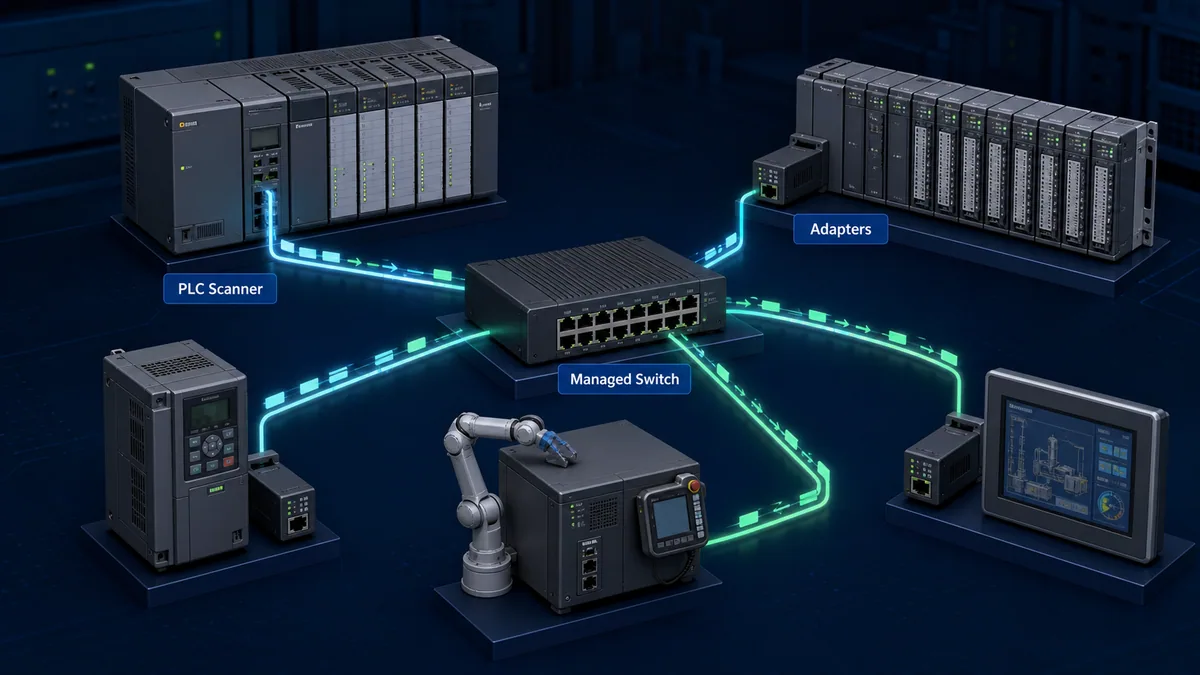
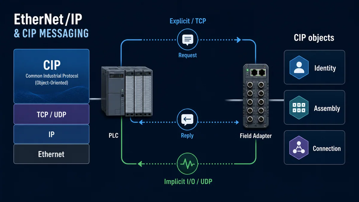
EtherNet/IP connects a PLC or controller acting as a Scanner Class product / connection originator to field Adapter Class products / connection targets such as remote I/O, drives, robots, weigh scales and instruments. The network uses the Common Industrial Protocol (CIP) object model over standard Ethernet and IP. Cyclic control data normally travels in implicit I/O connections over UDP, while configuration, diagnostics and general object services use explicit messages over TCP. An IP ping can succeed while the CIP identity, electronic key, connection path, assembly size, ownership or Requested Packet Interval is wrong.
Commission in this order: establish a controlled device/EDS and firmware baseline; assign and verify a unique IP configuration; compare the physical Identity Object with the project; choose an approved electronic-keying policy; select the documented connection and configuration/input/output assemblies; verify O→T and T→O byte sizes and ownership; choose RPI and timeout from an end-to-end capacity budget; map data and quality; then test connection loss, output failure behavior, switch/multicast diagnostics, DLR recovery where used, replacement and restart.
Never “fix” a connection by guessing assembly instances or disabling identity checks until the device happens to connect. Implicit I/O contains little information about what its bytes mean because that meaning was agreed when the connection opened. A wrong but accepted layout can move plausible byte patterns into the wrong PLC tags. Retain the exact EDS, vendor connection table, identity attributes, assembly instances, sizes, configuration data, RPI, ownership and tested firmware with the PLC project.
Understand EtherNet/IP roles and the CIP model
ODVA describes Messaging, Adapter and Scanner classes based on communication capability. A product can implement several functions, so role comes from its supported configuration—not from whether it is a PLC-shaped box.
Separate scanner, adapter and messaging responsibilities
| Role/class | Typical product | Connection responsibility | Evidence to retain |
|---|---|---|---|
| Scanner Class / originator | PLC, PAC, PC-based controller, robot controller | initiates real-time I/O connection requests and often explicit requests | configured interface, target identity/path, connection state and resources |
| Adapter Class / target | remote I/O, drive, robot, scale, instrument | accepts supported I/O connections and produces/consumes application assemblies | identity, EDS/profile, supported connections, assembly sizes and active owner |
| Messaging Class | HMI, programming tool, diagnostic/data application | exchanges explicit messages but does not provide real-time I/O as that class | authorized session, requested object/service and response status |
| peer/multi-role product | controller or intelligent device with scanner and adapter behavior | originates some relationships and targets others | each connection's owner, direction, path and failure behavior separately |
In modern CIP terminology, the node that sends Forward_Open is the originator and the node accepting it is the target. Engineering environments often still show scanner and adapter. Use both terms in documentation so technicians can join the project tree to the protocol evidence.
Treat every CIP device as objects, attributes, services and behavior
CIP is object-oriented. Objects expose attributes (data), services (requests/commands), connections and defined behavior. Common objects include Identity, Assembly, Connection Manager and TCP/IP Interface, while device profiles specify required object behavior and I/O formats for a device type. Vendors can also implement product-specific objects.
| CIP surface | Commissioning question | Typical fault if misunderstood | |---|---| | Identity Object | do vendor, device type, product code and revision match the approved project? | connection rejected by keying or wrong product accepted after checks are disabled | | Assembly Object | which instances produce inputs, consume outputs and receive configuration, and how many bytes? | Forward Open size/path error or shifted process data | | Connection Manager | did the originator request a supported connection, trigger, ownership and timing? | resource, ownership, path, parameter or timeout fault | | TCP/IP Interface | what IP, mask, gateway and allocation method are active? | duplicate/wrong subnet, unreachable device or controller pointed at old address | | Ethernet Link/port diagnostics | what link state, speed and counters exist at each interface? | physical path error hidden behind generic “device offline” alarm | | device/profile objects | what standardized or vendor-specific commands/status exist? | treating one drive/robot/control word layout as universal |
Control the EDS, profile and identity baseline
An Electronic Data Sheet describes a CIP device for engineering tools. Depending on the product and tool, configuration can use a vendor profile, Add-On Profile, EDS-based definition or a generic module where the engineer enters assembly data. These paths are not automatically equivalent in diagnostics or parameter support.
Use the most controlled supported integration path
| Integration option | Strength | Required control | Risk |
|---|---|---|---|
| vendor profile/add-on integration | rich named configuration, generated tags and diagnostics | exact tool/profile version and supported product firmware | project depends on vendor tool component availability |
| registered/installed EDS | portable identity, parameters and predefined connections as declared | vendor source, file version/integrity and engineering-tool support | EDS may not expose every vendor feature or current profile behavior |
| built-in device profile | consistent behavior for certified device type where implemented | verify exact profile/revision and supported connection | assuming every same-type device exposes identical optional data |
| generic Ethernet module/adapter | usable when vendor supplies authoritative assembly contract | manually record identity, assemblies, configuration, sizes, direction and data layout | highest risk of wrong instance/size/keying and weak diagnostics |
Install the EDS from the manufacturer or controlled repository. Preserve the original file and source, not only the catalog entry created in one workstation. ODVA's 2025 paper on EDS threats notes that EDS files are publicly shared and installed into varied engineering environments, so integrity and provenance belong in the change process.
Compare project and physical Identity Object
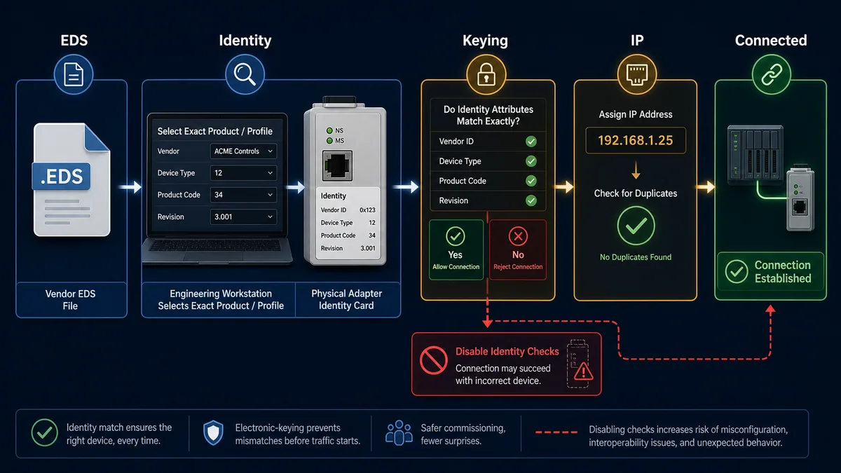
Electronic keying compares selected identity attributes before communication. Rockwell documentation describes policies such as Exact Match, Compatible Module and Disable Keying for its products; the exact behavior is product- and platform-specific. Exact Match can require vendor, product type/code and major/minor revision to match. Compatible Module can let a supported newer device emulate the configured revision. Disable Keying removes these identity checks even though data sizes/formats may still be checked.
| Keying policy | Intended decision | Replacement implication | Control rule |
|---|---|---|---|
| exact match | accept only the configured identity/revision combination | even a compatible minor revision can be rejected | use when exact approved revision is required and spares are controlled |
| compatible module | let the installed device decide whether it can emulate configured device | approved later compatible revision may connect | prove product-specific compatibility and regression behavior |
| disabled/no identity check | connection can proceed without comparing key attributes | wrong product can reach later size/configuration checks or connect unexpectedly | do not use merely to clear a mismatch; require documented risk decision |
Changing keying or device definitions online can interrupt this device and downstream/related connections. Preserve the fault first. Investigate why expected and actual identities differ; do not normalize an unauthorized replacement by weakening the project.
Assign and verify IP configuration
EtherNet/IP uses standard IP networking. A device may support static configuration, BOOTP/DHCP, rotary/switch addressing or vendor tools. The supported persistence and precedence vary. Record the method as well as the address so a replacement or power cycle behaves predictably.
Build an address register before commissioning
| Field | Example form | Why |
|---|---|---|
| equipment/location | RIO-PACK-02 / packaging cell |
binds network identity to the physical asset |
| MAC address | observed label/live value | distinguishes a newly discovered node before final IP |
| CIP identity | vendor, type, product code, revision, serial where exposed | proves device class/product rather than only network reachability |
| IP/mask/gateway | approved OT subnet values | routes/reaches only intended networks |
| allocation method | static, reserved DHCP/BOOTP, switch setting or supported tool | predicts persistence and replacement behavior |
| controller/project owner | scanner interface and project module name | prevents two projects claiming the same adapter |
| switch/VLAN/port | physical and logical path | helps locate duplicates, moves and discovery boundaries |
| change/test record | who, when, approved source and duplicate test | makes address changes auditable/recoverable |
During initial configuration, isolate the exact device or use a controlled discovery segment so an IP is not written to the wrong MAC. Verify the address is unused before assignment and test duplicate-IP diagnostics. After writing, read it back, power-cycle under an approved state, and confirm the planned allocation method remains active.
Separate IP reachability from CIP readiness
| Evidence | What it proves | What it does not prove |
|---|---|---|
| link LED | some physical/link negotiation | correct VLAN, IP, CIP identity or connection |
| ARP/MAC table | an IP-to-MAC/path observation | correct device role, ownership or data layout |
| ping | ICMP/IP request/reply if device permits | Forward Open, assembly, RPI or output validity |
| web page | an HTTP service responds | controller owns correct implicit I/O connection |
| explicit Identity read | CIP request reaches a responding identity | supported I/O connection/path/size is configured |
| established implicit connection | selected assemblies/timing were accepted | application tags are semantically correct or process behavior is safe |
Avoid using ping as the sole health tag. A field device can answer ping while its I/O connection has timed out, been rejected, lost ownership or reports invalid/faulted process data.
Configure assembly instances, sizes and directions
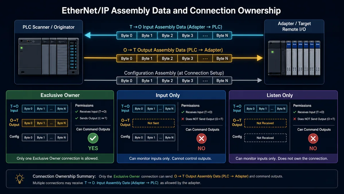
The Assembly Object groups application data for network exchange. Vendor documentation/EDS defines which instance is the adapter's produced input data, consumed output data and configuration data. Instance numbers and byte layouts are product-specific; common-looking numbers are not a standard map to copy between devices.
Translate originator-to-target and target-to-originator correctly
| Connection field | Record exactly | Common failure |
|---|---|---|
| connection point/path | configuration, O→T and T→O assembly instances or symbolic path | unsupported/path segment error |
| O→T size | bytes produced by originator and consumed by target | output size mismatch or shifted adapter data |
| T→O size | bytes produced by target and consumed by originator | input size mismatch or truncated data |
| configuration data | instance and byte payload if required | device rejects parameterization or starts in unintended mode |
| real-time format/header | pure data or supported status/run-idle format | correct assembly length appears wrong by header bytes |
| fixed/variable and priority | exact supported connection parameters | Forward Open rejects inconsistent parameters |
| trigger | cyclic, change-of-state or supported application trigger | timing/traffic differs from assumed cyclic behavior |
| transport | point-to-point/unicast or multicast as supported | unintended multicast or unsupported connection mode |
CODESYS exposes separate O→T and T→O byte sizes and can build a path from configuration, consuming and producing assemblies. Tool labels sometimes say input/output from the controller perspective and sometimes from the adapter perspective. Put both the protocol direction and plain-language producer/consumer in the interface contract.
Map every byte with quality and ownership
| Mapping field | Example form | Acceptance evidence |
|---|---|---|
| assembly/offset | T→O instance + byte/bit offset | matches retained EDS/vendor table and raw trace/tool view |
| data type/order | UINT16, signed integer, bitfield, float, bytes |
distinctive controlled pattern decoded correctly |
| semantic tag | DRIVE01_SPEED_ACTUAL |
joins process/device meaning, not generic Data[4] |
| units/scale/range | rpm, 0–1800, one count/rpm | compare known device display/reference values |
| status/quality | connection, device/profile status, data age | loss test invalidates use even if bytes remain in memory |
| ownership | one application/controller writes command | no HMI/service tool or second owner silently competes |
| handshake | command/status sequence or profile state | accepted/rejected/active state observed, not pulse-only assumption |
| version | interface, EDS/profile, firmware and project | backup can reproduce the exact layout |
Capture raw bytes before type conversion during commissioning. If raw bytes are correct and the engineering value is wrong, investigate offset, type, byte/word order and scale. If raw bytes are wrong, investigate assembly/path/size, configuration, device mode and data ownership.
Live mini-lab
Try it: press START, then STOP
A stop-dominant seal-in rung: START latches the motor output through its own contact, and STOP breaks the circuit.
Watch the output lamp: it stays on after START until you press STOP.
Free to start · runs in your browserOpens plcsimulationsoftware.com — same team
Choose connection ownership deliberately
ODVA training describes Exclusive Owner, Input Only and Listen Only I/O connection types. Exact support and dependencies come from the adapter.
Prevent multiple output owners
| Connection type | Receives target-produced input? | Sends originator output? | Ownership requirement |
|---|---|---|---|
| Exclusive Owner | yes as defined | yes | only one exclusive owner for that output connection; it configures/controls the adapter relationship |
| Input Only | yes | no application output | independent input consumption as supported; may carry configuration/heartbeat semantics |
| Listen Only | yes | no | depends on another owning connection's production; closes when required owner/producer relationship disappears |
Do not configure a second PLC as output owner merely for redundancy unless the exact adapter and controller architecture supports the intended redundant ownership/failover. A second controller that can see input data is not automatically permitted to write outputs. Document how ownership transfers, how stale commands are rejected and what the adapter does during the gap.
Define connection-loss output behavior
On connection timeout, an adapter can apply zero, hold last, predefined substitute values or device/profile-specific behavior. A drive can interpret loss through a communication-fault parameter; remote I/O modules can have per-channel fail states. There is no universal safe default.
| Event | Data/quality question | Output question | Recovery question |
|---|---|---|---|
| exclusive-owner timeout | does PLC mark T→O data stale immediately? | what O→T substitute occurs and after what timeout? | does reconnect automatically reapply command/configuration? |
| controller PROGRAM/STOP | does scanner keep connection and run/idle state? | device behavior in idle versus lost connection | are outputs reconciled before RUN resumes? |
| adapter power cycle | connection and identity unavailable | field/load behavior while electronics restart | startup parameter source and first accepted command |
| switch/link interruption | timeout relative to link/redundancy recovery | does process enter fail state for brief network loss? | alarm latch and automatic restart policy |
| second/listen consumer loss | primary owner/data producer still healthy? | normally no output authority for listener | listener rejoin and data freshness |
| configuration/key change | which connections are interrupted? | unintended output state during online reconfiguration | controlled maintenance state and regression test |
Standard EtherNet/IP I/O is not a functional-safety system. CIP Safety can transport safety data using certified products and a validated safety lifecycle, but a fast RPI, DLR ring, output fail value or electronic keying policy does not create a safety function.
Distinguish explicit and implicit messaging
Explicit messaging is request/reply communication to a named object, instance, attribute or service. It is flexible and normally used for configuration, diagnostics and non-time-critical information. Implicit messaging sends the agreed connection data without repeating its full semantic description and is normally used for real-time I/O.
Select the communication surface by purpose
| Need | Appropriate surface | Design caution |
|---|---|---|
| cyclic control/status | implicit I/O connection | approved assemblies, ownership, RPI, timeout and validity required |
| read device identity | explicit Identity Object service | identity response is not proof of valid I/O connection |
| parameter read/write | vendor/profile explicit object service or supported configuration assembly | respect operating mode, access, persistence and change control |
| frequent HMI tag data | controller/HMI service or supported connection | do not overload a field adapter with arbitrary polling |
| diagnostics | controller connection diagnostics plus explicit device/port objects | preserve CIP general/extended status and product code meaning |
| peer/controller data | produced/consumed or other supported CIP relationship | vendor/controller feature; define version, consumer count and failure state |
An explicit Set_Attribute or vendor service can change device behavior. Treat it like a configuration write with authorization, limits, readback and rollback—not a harmless diagnostic read. CODESYS's EtherNet/IP service example separates Get_Attribute_Single, Set_Attribute_Single and Reset operations; the object/service and device manual determine what is valid.
Decode connection establishment failures before retrying
A Forward Open includes timing, connection identifiers, transport/trigger, electronic key and connection path. Repeated retries do not correct a path or size error. Preserve the CIP general and extended status if the tool exposes it.
| Failure evidence | Likely boundary | Verify |
|---|---|---|
| connection path/segment error | wrong assembly/symbolic path or unsupported route | retained vendor connection path, instances and backplane/network route |
| invalid connection size | O→T/T→O bytes or real-time header mismatch | connection format and both directional sizes |
| keying/identity mismatch | physical product/revision differs | actual Identity Object versus project and approved keying policy |
| ownership conflict | another exclusive owner already active | adapter connection list and every controller/project |
| resource unavailable | connection limits or scanner/adapter resources exhausted | connection count, multicast/consumer and controller capacity limits |
| RPI/parameter rejected | unsupported interval or connection parameter combination | EDS/device minimum/maximum/granularity and task configuration |
| timeout after opening | packets not delivered/processed in window | switch path, multicast, task overruns, load and timeout settings |
Engineer RPI, timeout and controller-task capacity
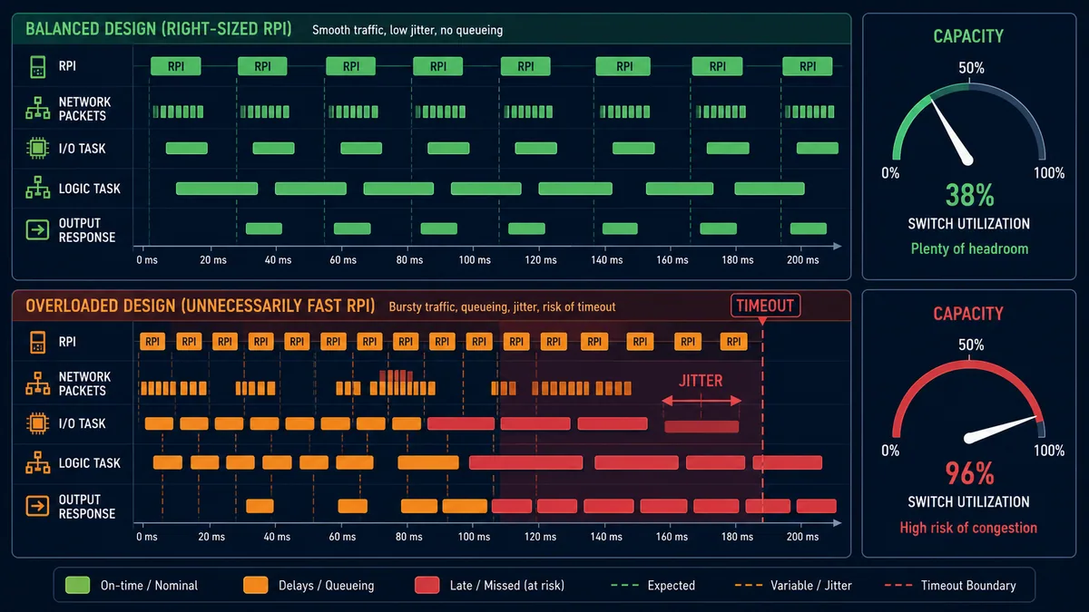
Requested Packet Interval is the interval at which the transmitting application is requested to produce connection data. It is a connection parameter, not a guarantee of complete sensor-to-actuator response. Different O→T and T→O parameters can exist even if a tool presents one simplified field.
Build a packet and latency budget
| Timing/capacity layer | Record | Test |
|---|---|---|
| sensor/device update | filter, conversion and internal production behavior | controlled input step/pulse and device timestamp/tool |
| each connection RPI | direction, packet size, trigger and consumer count | configuration export and live connection diagnostic |
| packet rate | packets per second by link/VLAN/switch plus multicast replication | calculated design compared with port capture/counters |
| adapter capacity | supported connections, packet rate and CPU/load limits | vendor limits and sustained worst case |
| scanner/controller | connection count, packet rate, CPU, I/O task period/priority | controller capacity tool/task monitor under process load |
| application task | period, phase, priority and I/O refresh behavior | trace field event through logic decision |
| timeout | RPI-derived connection timeout and process tolerance | authorized interruption/overload test and timestamped fault |
| margin | startup bursts, explicit traffic, HMI/engineering access and failure recovery | acceptance load scenario, not idle network only |
CODESYS documentation states its configured RPI must be a multiple of the bus-cycle task and describes a timeout delay derived from RPI and timeout multiplier. That formula is implementation/tool context, not a universal invitation to set arbitrary values. Use the exact controller and adapter rules.
If 100 connections change from 20 ms to 2 ms, the requested production rate increases by roughly ten times before considering directions, multicast replication or headers. Faster is not free. Group traffic by process need: high-speed interlock/position data, normal machine I/O, slow temperature/diagnostic data and explicit maintenance each deserve different treatment.
Diagnose RPI problems without masking them
If timeouts occur, preserve controller task overruns, connection counters/status, switch errors/discards, multicast state and CPU/network load. Increasing timeout can be correct when the original failure threshold was unjustified, but it can also lengthen stale-output/data exposure. Reducing every RPI can worsen queueing. Change one evidence-backed parameter within a capacity model and retest the failure response.
Design switching, multicast and DLR
EtherNet/IP can use star, linear and ring topologies. Standard switched Ethernet provides the path; managed features become important when multicast, segmentation, diagnostics, redundancy, traffic priority or security require them.
Manage multicast with IGMP deliberately
Implicit I/O can be unicast/point-to-point or multicast according to product and connection configuration. In a multicast producer-consumer design, IGMP snooping limits traffic to ports with interested consumers. ODVA's infrastructure guide states that when IGMP snooping is used, at least one IGMP querier is needed on the network.
| Multicast control | Healthy evidence | Failure pattern |
|---|---|---|
| IGMP snooping | membership table sends group only to joined consumer ports | disabled/failed snooping floods multicast to unnecessary devices |
| IGMP querier | one intentional active querier maintains membership | no querier causes membership aging/behavior that varies by switch |
| VLAN/subnet boundary | controller, producer and consumers are in planned multicast domain/routing design | traffic unexpectedly blocked or flooded across convergence boundary |
| connection transport | project and adapter agree on point-to-point or multicast | assuming all I/O is multicast or changing mode without capacity test |
| switch port counters | expected multicast/unicast rate with no unexplained discards | packet burst, oversubscription, loop or end-device overload |
Do not copy a switch template without verifying its querier, VLAN, QoS, storm-control, DLR and redundancy interaction. A restrictive security control that drops valid I/O is an availability failure; an open flat network that accepts any engineering host is a security failure. Test both normal and recovery traffic.
Treat DLR as path resiliency, not device redundancy
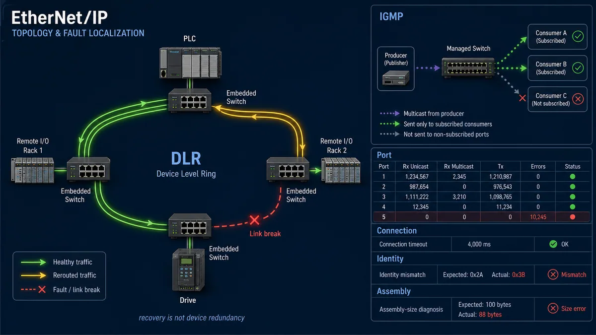
A DLR network has an active supervisor and ring participants; optional redundant gateways serve supported architectures. Supervisor capability can be disabled by default, so connecting a cable loop without an intentional active supervisor can create a harmful topology. Rockwell's 2025 network-device manual describes DLR as detecting, managing and recovering from single ring faults and notes that participants report fault locations to the active supervisor.
| DLR acceptance case | Observe | Pass boundary |
|---|---|---|
| healthy closed ring | active/backup supervisor roles, participants and no unexpected loop | exactly intended supervisors and normal state |
| open each approved link | fault location, recovery time, packet/connection/application trace | no connection/process consequence beyond design; diagnostics identify link |
| restore link | supervisor/ring transition and counters | stable normal return without flapping or duplicate-loop event |
| fail ring participant power | both embedded ports/device forwarding behavior | downstream/path effect matches product architecture; device itself remains failed |
| fail spur/non-ring node | affected scope | ring is not credited for failures outside protected path |
| load during fault | RPI jitter, timeout, switch/participant CPU/counters | capacity remains inside accepted recovery envelope |
Do not quote a generic DLR recovery figure as proof of application continuity. Measure the exact participant count, firmware, supervisor, traffic load, controller timeout and process behavior.
Troubleshoot EtherNet/IP by evidence layer
Start with the scanner interface and connection state, not a random field reset. Then check identity/keying, path/assemblies, ownership, timing, IP/path, switch/multicast and device/application diagnostics.
Symptom-to-evidence matrix
| Symptom | First discriminating check | Likely boundary | Avoid |
|---|---|---|---|
| every adapter offline | scanner interface/task and first upstream link/VLAN | controller mode, network adapter, switch/power or segmentation | editing all device IPs |
| one adapter pings but I/O faulted | CIP connection general/extended status | identity, keying, ownership, path, size, RPI or resources | replacing cable based on ping alone |
| identity mismatch | actual vendor/type/product/revision versus project | wrong product/firmware/profile or unauthorized replacement | disabling keying before compatibility review |
| invalid connection size | O→T/T→O format and byte counts | wrong EDS/profile/generic module or header selection | adding one byte until it opens |
| ownership conflict | active exclusive owner and other controller projects | second scanner/connection not permitted | power-cycling adapter without finding owner |
| input bytes update but tags wrong | raw assembly bytes/offset/type and configuration | mapping, byte/word order, scale or device mode | changing RPI first |
| outputs remain off | raw O→T command, owner state and device profile/status | application interlock/handshake, field power or adapter mode | forcing bits without status sequence |
| intermittent timeout | connection timestamps, controller task and both-end port counters | load, RPI, switch errors, power, connector, multicast or duplicate IP | increasing timeout and clearing logs |
| high multicast on all ports | IGMP snooping membership and active querier | switch/VLAN multicast configuration | assuming multicast flooding is required |
| ring normal becomes ring fault | DLR supervisor diagnostic and exact adjacent nodes | cable/port/participant power; redundancy margin lost | ignoring it because I/O remains connected |
| replacement visible but rejected | identity/keying, EDS/profile and assembly format | incompatible spare/revision or retained old IP/config | weakening keying as default repair |
| reconnects but machine will not resume | data quality, device/profile state and command reconciliation | application restart/interlock/handshake | repeatedly resetting connection |
CODESYS distinguishes unavailable devices, not-yet-configured/wrong-connection state and device-specific diagnostic logs. Other controllers use different icons and codes. Export the exact connection status and first error before automatic reconnect replaces it with a generic success state.
Preserve a reproducible incident packet
Record timestamp/time source, controller project/version/mode, scanner interface, adapter identity/IP/MAC, EDS/profile and firmware, connection path and sizes, RPI/timeout, ownership, general/extended CIP status, port/link/DLR/multicast counters, controller task/load, first process symptom and recovery action. Packet capture is useful when authorized, but it supplements the controller/adapter state and controlled configuration; encrypted CIP Security traffic can limit payload inspection by design.
Commission, replace and secure the system
Commission the relationship under a controlled machine/process state. A successful Forward Open is the beginning of acceptance, not the end.
EtherNet/IP acceptance matrix
| Gate | Test | Pass evidence |
|---|---|---|
| baseline | exact scanner/adapter products, certification, EDS/profile, firmware, topology and address list | controlled reproducible project package |
| discovery/IP | identify exact MAC/product; assign/read/power-cycle planned address method; duplicate test | unique stable identity/address on intended VLAN/port |
| identity/keying | compare actual CIP Identity with project under approved policy | accepted expected product; incompatible product is rejected |
| connection contract | verify path, assemblies, O→T/T→O/config sizes, trigger, transport and ownership | documented Forward Open with no generic guesses |
| data mapping | test distinctive raw and engineering input/output/profile values | every byte/bit, quality, scale and tag agrees |
| timing/capacity | worst planned RPI mix, explicit/HMI traffic and controller load | jitter, task, switch/adapter counters and headroom accepted |
| fault behavior | interrupt approved link, owner, adapter power and controller state cases | exact timeout, invalidation, output fail state, alarm and recovery |
| multicast | verify membership/querier and consumer delivery if used | traffic reaches only required ports with stable membership |
| DLR/redundancy | open/restore supported fault cases under load | bounded recovery and correct fault location/process behavior |
| replacement/restart | install approved spare and restart each endpoint | identity/configuration restored; data and fail behavior revalidated |
| security/recovery | roles, segmentation, services, CIP Security support, logs and offline backups | least necessary access plus tested restoration |
Use the industrial communication training path to rehearse connection, ownership, assembly and layered diagnostic reasoning before changing a plant network. It cannot certify the installed product, packet capacity, DLR, identity policy, cybersecurity, physical installation or process/safety behavior. The PLC remote I/O modules guide covers station power, module and channel boundaries; the EtherCAT PLC guide and PROFINET PLC guide show how other deterministic Ethernet systems model configuration and timing. For a Logix controller crossing that protocol boundary, use the Allen-Bradley EtherCAT gateway and Studio 5000 mapping guide to select the exact Scanner/Adapter and MainDevice/SubDevice roles.
Replace without erasing the cause
Before removal, capture Identity Object, IP/MAC/allocation method, LEDs, connection status, port/DLR state, active owner, assembly/path/RPI, firmware, device parameters and first fault. Verify the spare's exact compatibility and approved keying outcome. Restore the address/configuration using the supported process, then repeat identity, assembly, raw data, timing, fail-state and restart tests.
An automatic IP restore or compatible-key connection does not prove parameter, calibration or application compatibility. Controlled replacement evidence should show both “expected spare accepted” and “wrong/unapproved spare rejected.”
Apply CIP Security within defense in depth
ODVA describes CIP Security profiles using mechanisms including TLS/DTLS, device identity/certificates and security commissioning. Support is optional and product/firmware/tool-specific. Ordinary EtherNet/IP traffic is not automatically authenticated or encrypted merely because the product says EtherNet/IP.
Inventory the actual security capability of each endpoint. Segment OT networks, permit only required controller/engineering flows, restrict and monitor configuration services, disable unused switch/device ports and services where supported, protect EDS/profile/firmware provenance, manage credentials/certificates and keep tested recovery material. NIST SP 800-82 Rev. 3 requires OT security controls to account for performance, reliability and safety.
Diagnostic answer map for search and AI-assisted commissioning
| User or AI query | Concise answer | Required qualification |
|---|---|---|
| What is EtherNet/IP in a PLC? | CIP object and connection services carried over standard Ethernet/IP, with implicit real-time I/O and explicit configuration/diagnostics. | IP reachability alone does not prove a valid CIP I/O connection. |
| What is an EtherNet/IP scanner? | The Scanner Class/originator typically initiates I/O connections to adapter/target devices. | A product can implement multiple roles; verify the configured interface. |
| What is an EDS file? | A device-description file that exposes CIP identity, parameters and supported connections to engineering tools. | Match its vendor source/version to exact product and firmware; EDS is not firmware. |
| What are EtherNet/IP assembly instances? | Product-specific CIP Assembly Object instances grouping configuration, O→T output and T→O input bytes. | Never copy instance numbers or sizes from another product without its contract. |
| What does O→T mean? | Data from the connection originator, usually the PLC, to the target/adapter—normally outputs/commands. | Tool labels can use controller or device perspective; document producer and consumer. |
| What is RPI? | Requested Packet Interval is the requested production interval for connection data. | It is not total PLC/process response and must fit device/controller/network capacity. |
| Why can I ping a device but not connect? | Ping proves limited IP reachability; CIP can still reject identity, path, size, ownership, timing or resources. | Read the Forward Open general/extended status and actual identity. |
| Does EtherNet/IP require IGMP snooping? | Multicast designs commonly use IGMP snooping to limit delivery, with an active querier where snooping is used. | Point-to-point/unicast and exact switch/VLAN architecture can differ. |
| What does DLR protect? | A supported Device Level Ring can recover the Ethernet path from a single ring fault. | It does not duplicate the PLC, adapter electronics, field power or application state. |
| Is EtherNet/IP secure by default? | No; CIP Security can add protected transport/identity in supported systems within broader OT controls. | Verify the profile actually supported, commissioned and enforced end to end. |
Frequently asked questions
Is EtherNet/IP the same as standard Ethernet?
No. It uses standard Ethernet, IP, TCP and UDP at lower layers, then implements CIP objects, services and connections for automation. A normal switch can forward packets, but a working control relationship still needs compatible identities, assembly data, ownership, timing and diagnostics.
What is the difference between explicit and implicit EtherNet/IP messaging?
Explicit messaging is request/reply communication that names an object/service and is commonly used for configuration or diagnostics over TCP. Implicit messaging sends pre-agreed I/O connection data at a configured trigger/RPI, normally over UDP. “Implicit” describes implied data meaning, not hidden traffic.
Do I need an EDS file for every EtherNet/IP device?
Many engineering tools use an EDS or richer vendor profile; a generic connection can be possible when the manufacturer provides an authoritative path, assembly and data contract. The EDS alone may not provide all vendor-specific features. Use the integration method supported by both product and controller tool.
How do I find the correct EtherNet/IP assembly instances?
Use the exact product's vendor manual, controlled EDS/profile and connection table. Confirm configuration, O→T and T→O instances, byte sizes, real-time format and revision. A network scan can help discover supported data in some tools but must not overwrite a controlled project or interrupt an active adapter without an approved plan.
Why does an EtherNet/IP connection show an invalid size?
The originator requested O→T or T→O bytes that do not match the selected connection/path or included/omitted a required real-time header. Wrong EDS/profile, generic-module settings, firmware revision or connection format are common causes. Compare both directional sizes to the exact vendor contract.
Should I disable electronic keying to make a replacement connect?
Not as a troubleshooting shortcut. Capture the actual identity and determine whether the spare is approved and compatible. Disabling keying can permit a different device to accept configuration/data. Choose exact or compatible policy from the application's risk and product support, then test both accepted and rejected cases.
Is the fastest RPI always best?
No. Faster RPIs increase packet and processing load and can create bursts, queueing or controller-task pressure without improving a slow sensor/module/application task. Choose each connection from process latency and failure needs, calculate capacity, retain margin and measure under worst planned load.
What is the difference between Input Only and Listen Only?
Both can consume input data without controlling outputs where supported. An Input Only connection is an independent non-output connection; a Listen Only connection depends on an existing owning/producing connection and normally closes when that owner relationship disappears. Exact adapter behavior and allowed counts come from its EDS/manual.
Does DLR mean EtherNet/IP never disconnects?
No. DLR can quickly recover a supported single ring media fault, but application continuity depends on participant/supervisor behavior, load, RPI and timeout. It cannot keep a failed controller, adapter or power supply alive. Test every credited link fault and process consequence.
Can EtherNet/IP be used for safety I/O?
CIP Safety can provide functional-safety communication over supported networks using certified safety controllers/devices and validated parameters. Standard implicit I/O, DLR, fast RPI and ordinary output fallback are not safety functions. Follow the full hazard analysis, safety requirements, validation and change-control lifecycle.
Sources, review scope, and limitations
This guide was reviewed on August 28, 2026 against current public first-party documentation. EtherNet/IP features and limits vary by ODVA specification/profile, certification, scanner, adapter, EDS/vendor profile, firmware, engineering tool, assembly/connection, switch, network load and project. Verify the exact installed combination and retain the tested documentation revision.
- EtherNet/IP Technology Overview, publication 138R8 — ODVA
- What is EtherNet/IP?, publication 138R8 PDF — ODVA
- Common Industrial Protocol and the family of CIP networks — ODVA
- EtherNet/IP vendor quick-start handbook — ODVA
- Network Infrastructure for EtherNet/IP — ODVA
- CIP Security at a Glance — ODVA
- EDS files: threats and mitigations — ODVA
- EtherNet/IP Network Devices User Manual, ENET-UM006C — Rockwell Automation
- ControlLogix EtherNet/IP Network Devices User Manual, 1756-UM004F — Rockwell Automation
- EtherNet/IP scanner connection settings — CODESYS
- EtherNet/IP scanner diagnosis — CODESYS
- NIST SP 800-82 Rev. 3, Guide to Operational Technology Security
The images are conceptual and do not define compatible products, assembly instances, byte layouts, addresses, ports, switch configuration, RPI/capacity, DLR recovery, output failure states, security or safety functions. This page does not authorize uncontrolled network scanning, IP assignment, keying changes, output forcing, live packet interception, ring interruption, firmware work or safety validation. Only qualified, authorized personnel following the site risk assessment, controlled network access, electrical/hazardous-energy and process procedures, manufacturer documentation, management of change and functional-safety lifecycle should configure or test an installed system.
Now run it · free to start
Follow plant data from sensor to SCADA
Fieldbus versus Ethernet, Modbus, EtherNet/IP, PROFINET, OPC UA and MQTT, then SCADA layers and alarms, taught on simulated equipment. Free to start.
Ownership disclosure: PLC Programming IO and PLC Simulation Software are operated by the same publisher.
PLC Programming IO Editorial Team
Industrial automation education, references, and software testing
The PLC Programming IO Editorial Team publishes sourced industrial-automation education and documents how material is reviewed, tested, and corrected. A team byline means the publisher is responsible for the page; it does not represent a fictional person or imply an engineering licence.
Coverage:
- • PLC programming concepts and examples
- • Vendor software tutorials and comparisons
- • SCADA, HMI, protocols, and instrumentation
- • Training, careers, and reference material
Review standard:
- • Prefer primary and official sources
- • Record software versions when material
- • Separate tested facts from estimates
- • Publish material corrections
Important scope note
This site provides education, not project-specific engineering approval. Safety, code, and compliance decisions require a qualified person with access to the actual machine and jurisdiction.