Valve Positioner Explained: Operation, Calibration & Faults
Learn how pneumatic, electro-pneumatic and digital valve positioners turn a controller command into valve travel. Includes calibration steps, failure behavior and a free checklist.
A valve positioner is a local feedback controller that moves an actuator until measured valve travel matches the requested position. It receives a pneumatic or electrical command, compares that demand with stem/shaft feedback, and increases or exhausts actuator pressure to reduce the position error.
The process PLC or DCS usually controls flow, pressure, level or temperature. The positioner controls the inner mechanical position loop. That distinction explains why a correct 12 mA command does not prove the valve is at 50% travel—and why 50% travel does not necessarily produce 50% flow.
Download the valve-positioner calibration checklist (CSV).
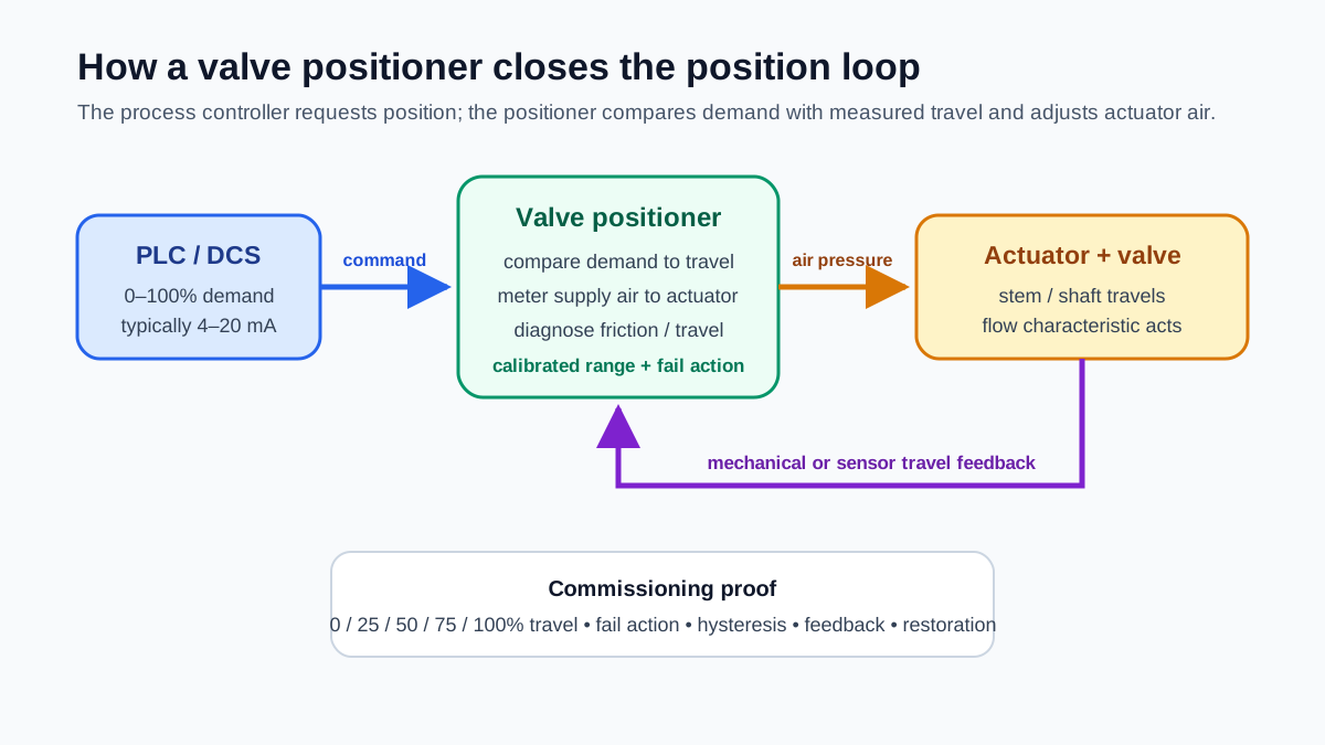
What a valve positioner does
Without a positioner, an actuator may receive a pressure signal directly. Packing friction, spring force, diaphragm area, process force and linkage can make the resulting travel differ from the intended position.
A positioner:
- reads the command;
- senses current stem or shaft position;
- calculates the position error;
- meters supply air to one or both actuator chambers;
- repeats until travel matches demand within its configured behavior.
Digital positioners may also provide travel feedback, pressure sensing, diagnostics, characterization, alerts and communication. Available features depend on the exact model and option set.
Main positioner types
| Type | Command | Internal behavior | Typical context |
|---|---|---|---|
| Pneumatic | usually 3–15 psi or project range | mechanical/pneumatic comparison and relay | legacy pneumatic control |
| Electro-pneumatic | typically 4–20 mA | converts current to pneumatic control and positions valve | common PLC/DCS analog output |
| Digital/smart | 4–20 mA and possibly digital communication | microprocessor control, travel sensing and diagnostics | modern process control |
A device may support HART, fieldbus or another protocol, but the name “digital positioner” does not guarantee a particular communication option.
Positioner, I/P converter and actuator
These components have different jobs:
- I/P converter: converts electrical current to pneumatic pressure.
- Positioner: closes the loop around measured valve position.
- Actuator: converts pneumatic, electric or hydraulic energy into motion.
- Valve body/trim: changes the flow path.
- Process controller: changes its output to regulate the process variable.
An electro-pneumatic positioner often contains an I/P stage, but a standalone I/P feeding an actuator is not automatically a positioner because it may have no travel feedback.
Signal path in a 4–20 mA installation
A typical loop is:
PLC/DCS analog output → 4–20 mA command → positioner
instrument-air supply → positioner relay → actuator chambers
stem/shaft sensor → positioner feedback controller
optional travel/status → PLC/DCS analog input or digital communication
For a linear configuration, 4 mA may represent 0% and 20 mA may represent 100%. Reverse action, split range and configured limits can change that mapping. Read the tag data sheet and current device configuration.
At 12 mA, the ideal normalized demand is:
(12 − 4) / 16 × 100% = 50%
That is a command percentage. It does not prove actual stem position, installed flow characteristic or process flow.
Air-to-open, air-to-close and fail position
The actuator/valve assembly’s failure response depends on spring direction, actuator type, pneumatic arrangement, stored energy, valve construction and accessories.
- Air-to-open: increasing actuator air tends to open the valve; spring return commonly drives it closed on air loss.
- Air-to-close: increasing air tends to close the valve; spring return commonly drives it open on air loss.
- Double-acting: air is directed to either actuator chamber; the failure state depends on configuration and accessories.
- Fail-in-place/lock-up: accessories may attempt to retain pressure/position, but leakage and process forces matter.
“Fail closed” is not universally safer. Cooling, fuel, pressure relief, reactor feed and inventory-isolation services can require different approved actions. The process hazard analysis and specification own the required failure state.
Direct and reverse positioner action
Positioner action describes how output pressure responds to the command/feedback relationship. It must be coordinated with actuator action and the control-system signal direction.
After configuration, prove the complete chain rather than reasoning from labels:
- command a small increase;
- observe which way the stem/shaft moves;
- verify the process tag’s open/closed convention;
- confirm the DCS/PLC faceplate direction;
- test signal and air failure;
- compare the result with the approved data sheet.
Live mini-lab
Try it: press START, then STOP
A stop-dominant seal-in rung: START latches the motor output through its own contact, and STOP breaks the circuit.
Watch the output lamp: it stays on after START until you press STOP.
Free · no signup to try · runs in your browserOpens plcsimulationsoftware.com — same team
Valve travel versus flow
Valve position is not the same as flow.
Flow depends on:
- valve coefficient and trim;
- inherent/installed characteristic;
- upstream and downstream pressure;
- fluid properties;
- piping/system resistance;
- cavitation, flashing or choking;
- valve size and operating point.
Linear, equal-percentage and quick-opening trim describe characteristic behavior under defined conditions. A digital positioner can also apply output characterization, but stacking characterization in both the controller and positioner can make behavior confusing. Assign one controlled owner.
Split-range control
Split ranging lets one controller output operate multiple final elements over different portions of its range. For example:
- Valve A responds from 4–12 mA.
- Valve B responds from 12–20 mA.
The overlap, gap, action and failure response must be deliberately engineered. Verify the process-control strategy, not just each positioner in isolation. At the crossover, poorly coordinated ranges can create deadband or both valves moving unexpectedly.
See split-range control and control valve basics.
Position feedback and diagnostics
Position feedback may be:
- a local mechanical indicator;
- internal sensor value used by the positioner;
- retransmitted 4–20 mA travel signal;
- digital travel/status data;
- separate open/closed limit switches.
Do not label command as feedback. The tags should communicate source and meaning, such as:
FV101_PositionDemandFV101_TravelFeedbackFV101_OpenLimitFV101_TravelDeviationFV101_DeviceStatusValid
Smart positioner diagnostics can indicate travel deviation, excessive cycling, supply pressure issues, friction or other conditions. Diagnostic interpretation and alert support vary by model and installation. Use the manufacturer’s documentation and a verified baseline rather than treating every advisory as a process trip.
Calibration and commissioning procedure
This is a general workflow. The exact device manual, site method, process isolation and safety requirements control the job.
1. Establish a safe work state
Changing output can move the valve and alter the process. Obtain permits, coordinate with operations, isolate energy/process where required, and control any bypasses or overrides. Treat stored pneumatic and mechanical energy explicitly.
2. Verify the assembly
Record:
- valve and positioner tag;
- valve/actuator/positioner model;
- travel or rotation range;
- linkage and mounting;
- air-to-open/close configuration;
- required fail action;
- supply-air pressure and quality requirements;
- command and feedback ranges;
- hazardous-area approvals where relevant.
Inspect tubing, fittings, gauges, filters/regulators, linkage tightness and obstruction.
3. Confirm command and air supply
Measure the incoming current with an approved loop method. Verify polarity, loop power/burden and output ownership. Check supply pressure against the actuator/positioner specification—more pressure is not automatically better and may exceed equipment ratings.
4. Perform device setup
Many digital devices have an automatic travel calibration. It may drive the valve through its range. Confirm movement is permitted before initiating it. Configure travel limits, actuator style, feedback orientation and other required parameters from the approved data sheet.
5. Check multiple points
Command 0%, 25%, 50%, 75% and 100%, then descend through at least selected points. At each point record:
- command mA/percentage;
- local travel;
- digital position value;
- retransmitted feedback;
- direction of approach;
- settling behavior;
- deviation and acceptance result.
Acceptance criteria come from the project and equipment specification. A universal ±1% rule is not appropriate for every valve, actuator and service.
6. Test fail response
Using the approved procedure, test relevant cases:
- command-signal loss;
- instrument-air loss;
- electrical power loss;
- communication loss;
- position feedback failure;
- travel deviation or obstruction.
Record actual direction, final position, alarm/status and control-system reaction.
7. Restore and document
Return the valve to the authorized process position, remove test sources/overrides, restore tubing and signal ownership, confirm feedback is valid, and obtain operations acceptance. Save the final configuration or signature according to the project’s device-management practice.
Emerson’s current FIELDVUE DVC2000 instruction manual provides a device-specific example of installation, setup, calibration and maintenance requirements. Always use the manual for the exact installed model.
Worked example: 4–20 mA control valve
FV-301 is configured air-to-open with 4 mA = 0% demand and 20 mA = 100%. The approved failure action is closed on loss of air.
| Command | Expected demand | Observed travel | Interpretation |
|---|---|---|---|
| 4.00 mA | 0% | 0.2% | compare with project deadband/tolerance |
| 8.00 mA | 25% | 24.8% | acceptable only against specified criterion |
| 12.00 mA | 50% | 49.9% | midpoint agreement |
| 16.00 mA | 75% | 74.7% | record approach direction |
| 20.00 mA | 100% | 99.4% | confirm mechanical stop is not overstressed |
On the descending test, 12 mA produces 49.0%. The 0.9 percentage-point directional difference may indicate mechanical hysteresis, packing friction, linkage play or normal behavior within the approved specification. Do not “fix” it by altering PLC scaling until the mechanical/device loop is diagnosed.
Common valve-positioner problems
| Symptom | What to check |
|---|---|
| No movement | air supply, isolation, command current, I/P, tubing, actuator, mechanical obstruction |
| Moves opposite direction | configured action, feedback orientation, tubing ports, actuator action, PLC output direction |
| Hunts/oscillates | positioner tuning, linkage, stiction, oversized actuator/valve, process-loop interaction |
| Slow response | air capacity, filter/regulator, tubing, actuator volume, positioner settings, packing friction |
| Cannot reach full travel | travel stops, supply pressure, actuator sizing, calibration, obstruction |
| Travel differs by direction | stiction, backlash, packing, linkage or calibration |
| Correct travel, wrong feedback | retransmitter calibration, scaling, wiring or tag mapping |
| Travel deviation alarm | obstruction, insufficient air, actuator leak, feedback problem or unrealistic timing |
| Valve position correct, process wrong | process conditions, trim, sizing, upstream/downstream restrictions, bad process measurement |
Diagnose from the inside out: command, positioner demand, pneumatic output, actual travel, feedback and process effect.
PLC/DCS integration checklist
- Analog output range and fail behavior are documented.
- Command and actual travel use separate tags.
- Signal quality/communication status is exposed.
- Position deviation has an appropriate delay and operator action.
- Open/closed status reflects proved travel, not command alone.
- Manual/Auto and cascade ownership are clear.
- Output tracking supports bumpless mode transfer where required.
- Split-range ownership and crossover are controlled.
- Positioner characterization is not duplicated unknowingly.
- Air/signal failure response matches the approved hazard basis.
- Calibration and final configuration are retained as evidence.
Primary references
- Emerson, FIELDVUE valve positioners.
- Emerson, FIELDVUE DVC2000 digital valve controller instruction manual, August 2025.
- Fluke, What is a 4–20 mA current loop?.
- OSHA, 29 CFR 1910.147 control of hazardous energy.
Continue learning
Now run it · free · no signup
Diagnose a PLC fault in your browser
Start with a no-account motor diagnostic, then work through guided wiring, logic and scan-order fault labs with graded feedback.
Ownership disclosure: PLC Programming IO and PLC Simulation Software are operated by the same publisher.


