PLC Ladder Logic Instructions & Symbols: Complete Reference
Use a deep PLC ladder logic instruction reference covering contacts, coils, edges, timers, counters, data, math, control flow, vendor dialects, scan behavior and a printable symbol chart.
Quick answer: A PLC ladder instruction either tests a condition, writes a result, retains state, transforms data or calls another operation. A positive contact is true when its Boolean operand is
TRUE; a negated contact is true when that operand isFALSE; an ordinary coil writes the incoming rung condition. Timers, counters and edge detectors have instance state. Math, compare, move and block-call instructions operate on typed data. The common intent transfers between platforms, but mnemonics, operands, retentivity, timing, error behavior and online rules do not—verify the exact controller's current instruction reference.
Use this page as a behavioral lookup, not a list of icons. Start with the instruction family, identify what it reads and writes, decide whether it owns state, predict its result for the current scan, then verify platform semantics and test restart and fault cases. The broader ladder programming tutorial owns the end-to-end learning workflow; this page owns instruction and symbol reference intent.
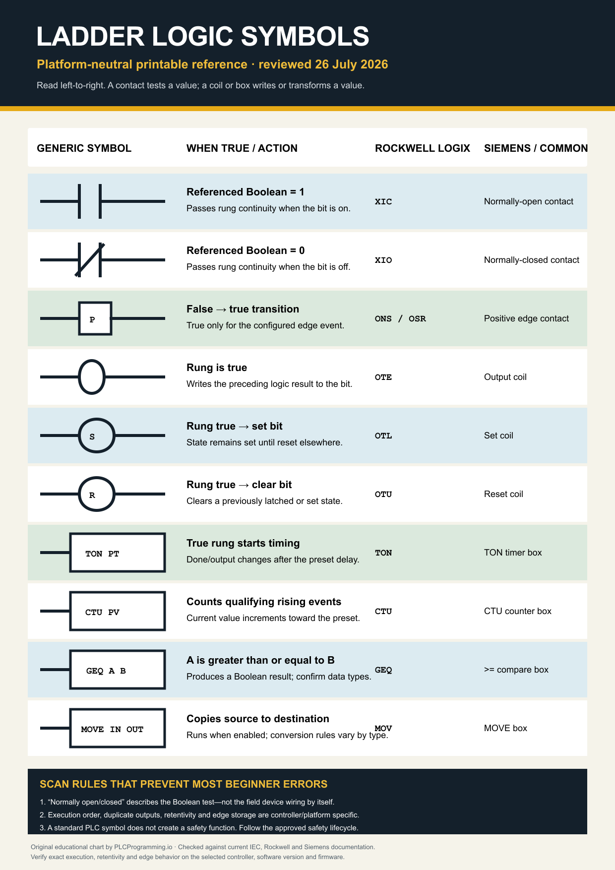
Take the reference with you: download the printable PDF, download the editable SVG, or open the full-resolution PNG. These files are free to use in a classroom or internal project document with attribution to PLCProgramming.io; do not present them as a substitute for the selected controller's instruction manual.
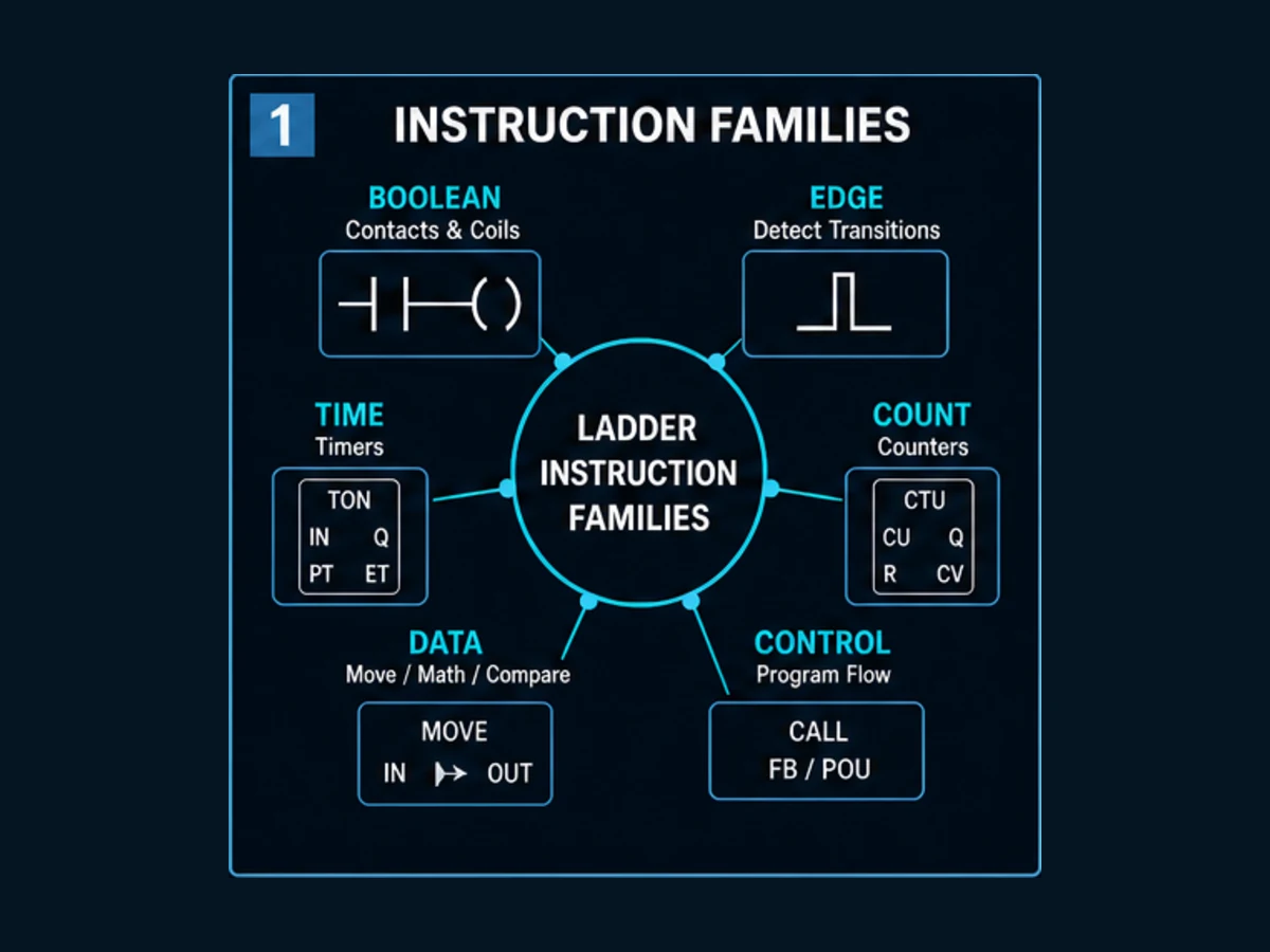
PLC ladder logic instruction families at a glance
Do not select an instruction by appearance alone. Select it from the state transformation the requirement needs. The table below is deliberately generic: it gives you the question to answer before translating to Logix, Siemens LAD, Omron, Mitsubishi, CODESYS, Beckhoff or Schneider syntax.
| Family | Generic examples | Reads | Writes or retains | First verification question |
|---|---|---|---|---|
| Boolean tests | positive contact, negated contact, AND/OR branch | Boolean value and incoming rung condition | outgoing rung condition only | is the tag meaning documented separately from physical NO/NC wiring? |
| Boolean writes | coil, negated coil, set, reset | incoming rung condition | Boolean destination; set/reset may retain state | can any other rung, task, HMI or force write the same destination? |
| edge detection | rising edge, falling edge, one-shot | current input and prior-call state | one-execution pulse plus hidden/explicit memory | what initializes the storage bit at startup and who owns the instance? |
| timers | TON, TOF, pulse, retentive timer | enable, preset, reset and elapsed time | elapsed/state outputs in an instance | what time base, task behavior, reset and restart semantics apply? |
| counters | CTU, CTD, CTUD | count edges, preset and reset/load | current count and status in an instance | does the instruction count levels or qualifying transitions? |
| compares | equal, not equal, greater/less, range | two or more typed values | Boolean condition | how are NaN, signedness, tolerance and type conversion handled? |
| arithmetic | add, subtract, multiply, divide, compute | typed numeric operands | numeric result and sometimes status | what happens on overflow, divide-by-zero or precision loss? |
| data movement | move, copy, fill, pack/unpack, convert | source value or range | destination value or range | are source/destination sizes, overlap and byte order compatible? |
| selection/limits | select, minimum, maximum, limit | condition and typed values | selected or clamped value | does the requirement need clamping, rejection or an explicit quality flag? |
| arrays/queues | index, file search, FIFO/LIFO, shift | array, index and control state | array elements and control structure | how are bounds, completion and partial execution handled? |
| program control | jump, label, return, subroutine/POU call | rung condition and call parameters | execution path and called-state effects | can skipped logic leave stale outputs, timers or diagnostics? |
| communication/I/O | message, read/write, module status | configuration, request and remote data | status, response and destination data | is execution asynchronous, and who owns busy/done/error recovery? |
| reusable/process blocks | motor, valve, PID, alarm, custom FB/AOI | explicit interface plus instance state | outputs, diagnostics and retained state | is this a certified/library/versioned block with a testable contract? |
Read, write, state and call: the four questions behind every instruction
An instruction name is less important than its contract. Ask four questions in order:
- What does it read? A contact may read one bit; an
ADDreads typed operands; a message block reads a configuration and trigger. Include the incoming rung condition where the platform uses it as an enable. - What can it write? Find every destination, status member and in-out parameter. A block that appears to return one Boolean may also update elapsed time, error state or an entire control structure.
- What state survives this call? An ordinary compare is normally stateless. A timer, edge detector, counter, queue or asynchronous communication block needs memory that must belong to one intentional instance.
- What happens when it is not executed? Disabled, skipped and false-rung behavior are not synonyms. A skipped block may not update outputs; a called-but-disabled block may deliberately clear or hold them. This distinction is a frequent migration defect.
For online diagnosis, write the expected answer to all four before looking at highlighted rung colors. Online animation is evidence, not the requirement. A green path can still carry stale, forced, simulated or poor-quality data.
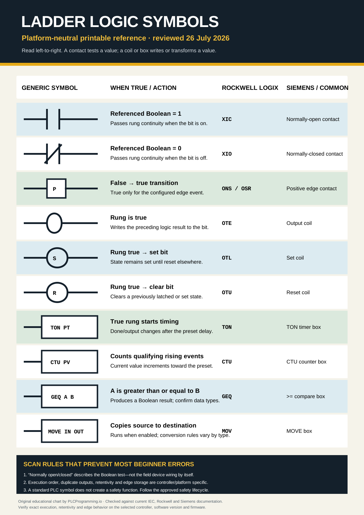
Ladder logic instruction and symbol chart
| Generic symbol or box | Logical behavior | Rockwell Logix name | Siemens / common name |
|---|---|---|---|
| `— | —` | True when the referenced bit is 1 |
|
| `— | / | —` | True when the referenced bit is 0 |
| Positive-edge contact | True for the implementation-defined rising-edge event | ONS or OSR, depending on use | Positive signal edge |
—( )— |
Writes the rung result to a Boolean | OTE | Output coil |
—(S)— |
Sets a Boolean when the rung is true | OTL | Set coil |
—(R)— |
Clears a Boolean when the rung is true | OTU | Reset coil |
| TON box | Starts a non-retentive on-delay when enabled | TON | TON |
| CTU box | Counts qualifying rising events | CTU | CTU |
| Compare box | Returns a Boolean result such as A >= B |
GEQ | >= compare |
| Move box | Copies a source into a destination when enabled | MOV | MOVE |
This mapping is intentionally behavioral rather than decorative. Editor artwork changes between platforms and versions, while the truth condition is what determines whether power continuity reaches the next instruction. Rockwell's XIC/XIO names are vendor terms; they do not mean the referenced field contact is physically closed or open.
Introduction: the visual language is only the surface
Ladder Diagram uses a relay-like visual grammar, but a controller evaluates variables and calls software operations; it does not energize the drawing. Understanding the symbols is necessary for reading a program, yet reliable work requires the operand types, task and call order, instance ownership, startup state, diagnostic quality and writer precedence behind those symbols.
The visual form can make Boolean relationships and online state easy to inspect. It can also conceal important state inside a timer, counter, edge detector, reusable block or asynchronous request. Treat the left-to-right path as an execution model for the selected platform, not literal electrical continuity and not proof that the field device is healthy.
IEC 61131-3 supplies a shared Ladder Diagram language model. Vendors add instruction families, data types, editor rules and controller services, and even similarly named standard function blocks can be embedded in different task, memory and online-change models. Shared terminology supports translation; it does not make projects or behaviors copy-and-paste compatible.
Modern Ladder Logic has evolved far beyond simple contact-and-coil logic to include sophisticated function blocks for mathematical operations, communication, data manipulation, and advanced control algorithms. However, the basic symbols remain the foundation upon which all complex control systems are built.
This reference covers the main transferable instruction categories and routes model-specific details to official manuals. It cannot list every motion, process, safety, drive, communication or application instruction available in every firmware revision. A vendor's current instruction locator remains authoritative for availability, operands and restrictions.
The practical goal is to explain what an instruction will do for the current input history, what it remembers, what it can change, and how you would prove the result. That skill transfers better than memorizing a long mnemonic list.
Chapter 1: Fundamental Contact Symbols
Normally Open (NO) Contacts
The normally open contact represents the most basic element in Ladder Logic programming, symbolizing a contact that allows current flow when the associated input condition is TRUE (energized) and blocks current flow when the condition is FALSE (de-energized).
Symbol Representation: The NO contact appears as two parallel vertical lines with a gap between them, resembling an open electrical switch. This universal symbol is consistent across all PLC platforms, though some manufacturers may use slightly different line weights or styling.
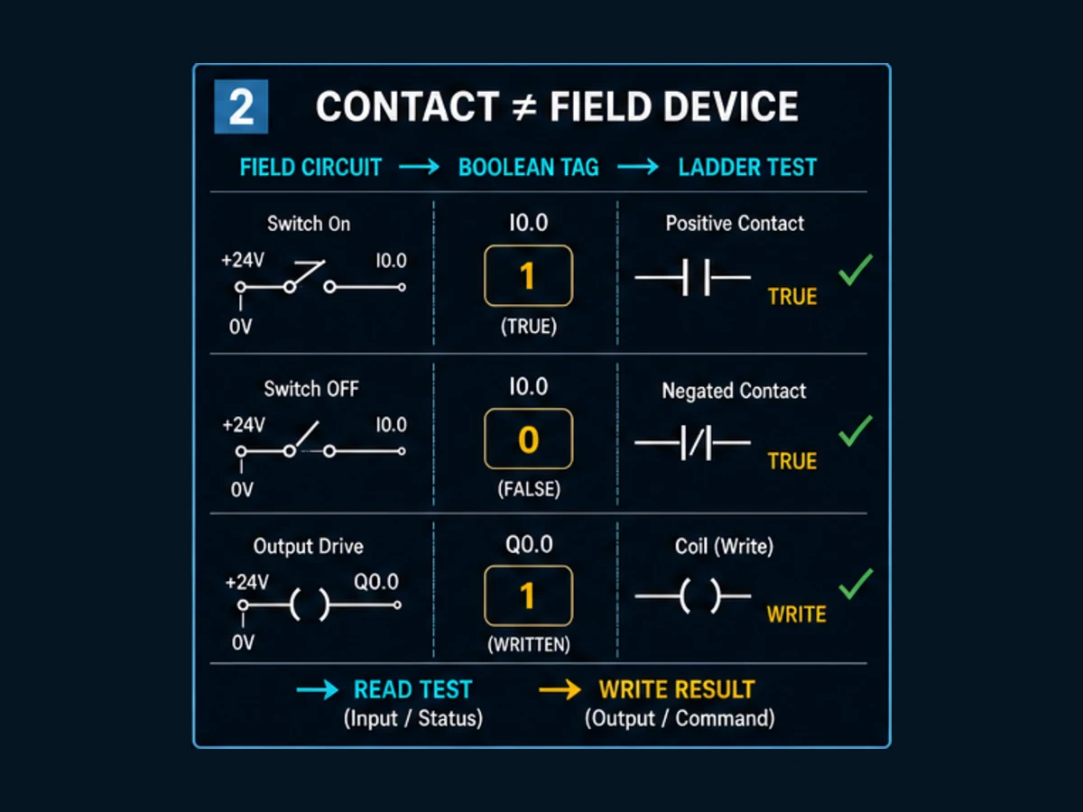
Electrical Analogy: In a relay drawing, a normally open contact describes a physical device state. In ladder software, the positive contact usually asks whether its Boolean operand is TRUE. The physical circuit may be wired NO or NC and the input-conditioning layer may invert or qualify it, so the electrical and software meanings must be documented separately.
Programming Applications: Positive contacts test conditions that must be true for continuity to proceed. Operands may represent validated requests, feedback, modes or internal state; direct raw-I/O use should preserve quality and polarity meaning. Safety-related signals require the approved safety architecture and instruction set, not an ordinary contact chosen from appearance.
Logic Behavior: When the associated input or memory bit is energized (TRUE), the NO contact allows power flow to continue to the right in the ladder rung. When de-energized (FALSE), the contact blocks power flow, preventing downstream logic from executing.
Addressing and Naming: NO contacts are typically addressed using the input address or memory bit designation associated with the physical or logical signal they represent. Proper naming and documentation of contact functions is essential for maintainable programming.
Best Practices: Name Boolean tags so their healthy or active meaning is explicit, such as GuardCircuitHealthy, then choose the positive or negated test that reads closest to the requirement. Do not mechanically prefer one symbol; prefer a clear condition and a documented quality policy.
Normally Closed (NC) Contacts
The normally closed contact represents the logical inverse of the normally open contact, allowing current flow when the associated condition is FALSE and blocking flow when the condition is TRUE.
Symbol Representation: The NC contact appears as two parallel vertical lines with a diagonal line crossing through them, indicating a closed contact that opens when activated. This diagonal line distinguishes NC contacts from NO contacts in Ladder Logic diagrams.
Electrical Analogy: In electrical circuits, normally closed contacts represent components that conduct electricity in their resting state and interrupt conduction when activated. Examples include normally closed pushbuttons and safety switches that must remain closed for normal operation.
Programming Applications: NC contacts are commonly used for safety systems, stop buttons, alarm conditions, and interlocks that must remain satisfied for normal operation. They're also used in logic that should execute when certain conditions are NOT present.
Logic Behavior: When the associated input or memory bit is de-energized (FALSE), the NC contact allows power flow to continue. When energized (TRUE), the contact opens and blocks power flow, interrupting the logic path.
Safety Boundary: A negated software contact is not a fail-safe circuit. De-energize-to-trip wiring, discrepancy detection, diagnostic coverage, safety-rated input hardware, logic, final elements and validation belong to the risk-reduction design. A broken wire can only produce the intended response when the complete circuit and application are designed to detect it.
Troubleshooting Considerations: Understanding NC contact behavior is crucial for effective troubleshooting. A rung that isn't executing might be due to an unexpected TRUE condition on an NC contact rather than a FALSE condition on an NO contact.
Contact Symbols in Series and Parallel
The arrangement of contacts in series (AND logic) and parallel (OR logic) configurations creates the fundamental logical operations that control industrial processes and equipment.
Series Configuration (AND Logic): When contacts are placed in series on the same rung, ALL contacts must allow power flow for the rung to execute. This creates logical AND operation where multiple conditions must be simultaneously TRUE for outputs to energize.
Parallel Configuration (OR Logic): When contacts are arranged in parallel branches, power can flow through ANY of the parallel paths. This creates logical OR operation where any one of several conditions can cause outputs to energize.
Mixed Logic Configurations: Real-world control applications typically combine series and parallel contact arrangements to create complex logical expressions that meet specific operational requirements. Understanding how these combinations work is essential for effective programming.
Documentation Practices: Complex contact arrangements benefit from clear documentation including logic descriptions, operational sequences, and safety considerations. Well-documented programs are easier to troubleshoot, modify, and maintain.
Optimization Strategy: Arrange contacts to express the requirement, expose the most useful diagnostic reason and preserve deliberate evaluation order. Do not reorder logic from a generic “frequently true/false” rule; compiler and runtime evaluation differ, and micro-optimization can make fault diagnosis harder without a measured timing benefit.
Troubleshooting Techniques: Understanding series and parallel contact behavior enables systematic troubleshooting approaches that can quickly identify which conditions are preventing rung execution or causing unwanted operation.
Chapter 2: Output and Coil Symbols
Output Coil Symbols
Output coils represent the actions taken when ladder logic conditions are satisfied, energizing physical outputs or setting internal memory bits to control equipment and system states.
Standard Output Coil: The basic output coil appears as a circle or oval on the right side of ladder rungs, representing an output that energizes when the rung logic is TRUE and de-energizes when FALSE. This symbol directly corresponds to physical outputs or internal memory bits.
Latched Output Coil: Also called a SET coil, this symbol (typically shown as a circle with an 'S' inside) energizes an output that remains energized even after the rung logic becomes FALSE. Latched outputs require separate RESET logic to de-energize them.
Unlatched Output Coil: The RESET coil (typically shown as a circle with an 'R' inside) de-energizes a latched output when the rung logic becomes TRUE. RESET coils are used in conjunction with SET coils to create maintained memory functions.
Negated Output Coil: Some PLC platforms provide negated output coils that energize when rung logic is FALSE and de-energize when logic is TRUE. These coils provide convenient inverse logic operation for specific applications.
One-Shot Output Coils: These specialized coils energize for only one scan cycle when rung logic transitions from FALSE to TRUE, regardless of how long the input conditions remain TRUE. One-shot coils are useful for triggering actions that should occur only once per input transition.
Retentive Outputs: Some systems provide retentive output coils that maintain their state through power cycles and program downloads. These coils are useful for maintaining critical system states during power interruptions or system updates.
Internal Memory and Flag Symbols
Internal memory bits and flags provide temporary storage and logic control capabilities that don't directly control physical outputs but enable complex program logic and data management.
Internal Relay Bits: These memory locations appear as standard coil symbols but address internal memory rather than physical outputs. Internal relays enable complex logic operations, temporary data storage, and program flow control without affecting external devices.
System Flag Bits: PLCs provide system-generated flags including first scan bits, always-on bits, clock pulses, and diagnostic flags that programs can use for timing, initialization, and system monitoring functions.
User-Defined Flags: Programmers can create custom flag bits for specific application needs including sequence step tracking, mode selection, alarm acknowledgment, and inter-routine communication.
Timer and Counter Done Bits: Timer and counter instructions generate done bits that programs can use as contacts in other logic rungs. These bits provide indication when timing or counting operations have completed.
Communication Status Bits: Network communication instructions typically provide status bits indicating communication success, failure, or progress that programs can monitor for diagnostic and error handling purposes.
Alarm and Diagnostic Bits: Many applications use internal bits to track alarm conditions, diagnostic states, and system health indicators that operator interfaces can monitor and display.
Chapter 3: Timer and Counter Symbols
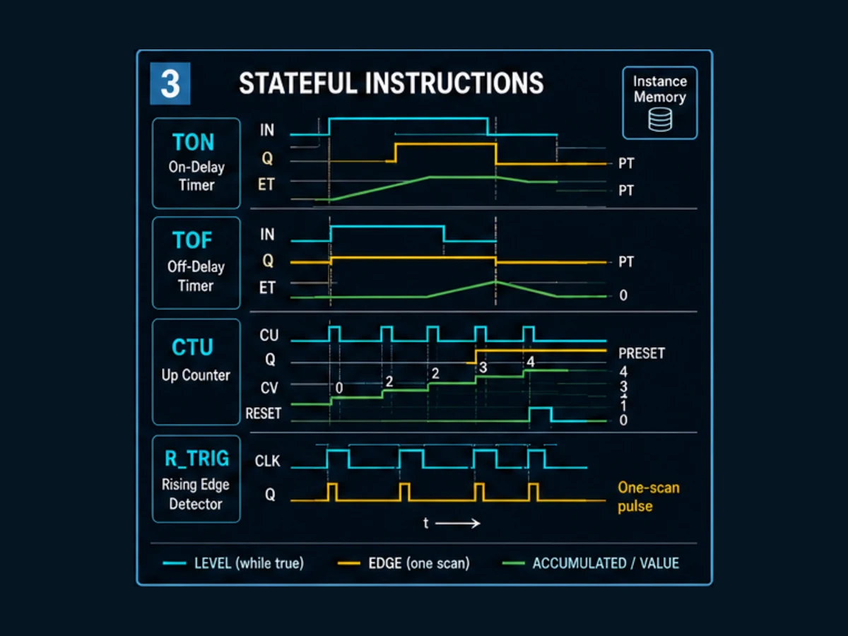
Timers, counters and edge detectors are stateful. Two calls to one instruction type need two independent instances unless the requirement deliberately shares state. Reusing a timer or edge-storage object across unrelated devices creates history coupling that a static rung screenshot will not reveal.
| Stateful instruction | Trigger model | State to inspect | Reset/restart question |
|---|---|---|---|
| TON | enabled level accumulates until preset under the selected implementation | elapsed time, output, enable/status and instance identity | does false input clear elapsed state, and what does task interruption do? |
| TOF | output/deactivation timing follows a falling enable transition | output and elapsed state during off-delay | what happens if input returns true before expiry? |
| pulse timer | transition starts a defined pulse | pulse output, elapsed and retrigger state | is the pulse retriggerable or ignored while active? |
| retentive timer | enabled intervals accumulate until a reset policy clears them | accumulated time, done state and retention configuration | does controller restart, download or mode change retain the instance? |
| CTU/CTD | qualifying transitions alter current value | current value, threshold output, overflow and prior-input state | what initializes the edge memory and how is reset prioritized? |
| R_TRIG/F_TRIG | current versus prior input produces a one-call pulse | prior input and pulse output | what is the first-call behavior when input starts true? |
Timer Symbols and Functions
Timer symbols in Ladder Logic represent time-delay functions that are essential for controlling sequential operations, providing delays, and implementing time-based control strategies.
Timer On-Delay (TON): The most common timer function provides a time delay before energizing its done bit. The TON timer starts timing when its enable input becomes TRUE and sets its done bit when the accumulated time equals the preset value.
Timer Off-Delay (TOF): This timer provides a time delay before de-energizing its done bit. The TOF timer's done bit is normally TRUE and de-energizes for the preset time period after the enable input becomes FALSE.
Retentive Timer (RTO): The retentive timer maintains its accumulated time value even when the enable input becomes FALSE. RTO timers continue accumulating time each time the enable input becomes TRUE until reset by separate reset logic.
Timer Symbol Representation: Timer symbols typically appear as rectangular blocks containing timer type designation (TON, TOF, RTO), preset value, accumulated value, and enable/reset inputs. Output connections include done bits and timing bits.
Time Representation: Older timer families may use controller-specific integer time bases; IEC-style blocks commonly use typed TIME values such as T#250ms. Resolution, accuracy, update interval and maximum range are different concepts. Confirm all four rather than inferring timing performance from the displayed literal.
Timer Outputs and Members: A generic IEC timer exposes outputs such as Q and elapsed time ET; a Logix timer structure exposes members such as enable, timing, done, preset and accumulator. These are not universal aliases. Build the diagnostic view from the selected instruction's documented interface.
Counter Symbols and Applications
Counter symbols represent counting functions that track events, quantities, or cycles in automated systems, providing essential functionality for production counting, batch operations, and sequence control.
Count Up (CTU): The count-up counter increments its accumulated value each time its count input transitions from FALSE to TRUE. The CTU counter sets its done bit when the accumulated count equals or exceeds the preset value.
Count Down (CTD): The count-down counter decrements its accumulated value on each FALSE-to-TRUE transition of its count input. The CTD counter sets its done bit when the accumulated count reaches zero.
Count Up/Down (CTUD): This bidirectional counter can both increment and decrement its accumulated value based on separate up-count and down-count inputs. CTUD counters provide flexible counting functionality for complex applications.
Use the PLC counter guide for scan traces, reset/load priority, retention, rollover, high-speed selection, vendor translation and the full acceptance matrix.
Counter Interface: IEC-style counters expose typed inputs and outputs such as CU, R, PV, Q and CV; other platforms use a control structure with accumulator, preset and status members. Count direction, saturation or wrap, overflow and reset priority must be verified for the target implementation.
Preset Value Configuration: Counter preset values can typically be constants entered during programming or variables that can be modified during runtime to provide flexible counting parameters for different products or operating modes.
Counter Applications: Common counter applications include production counting, batch quantity control, cycle counting for maintenance scheduling, and sequence step tracking in automated processes.
Chapter 4: Mathematical and Data Manipulation Symbols
Numeric ladder code needs a value path and a quality path. Moving or scaling a bad raw value into engineering units does not make it valid. Carry range status, stale/communication status and substitution ownership beside the number, and prevent an invalid measurement from silently driving a command.
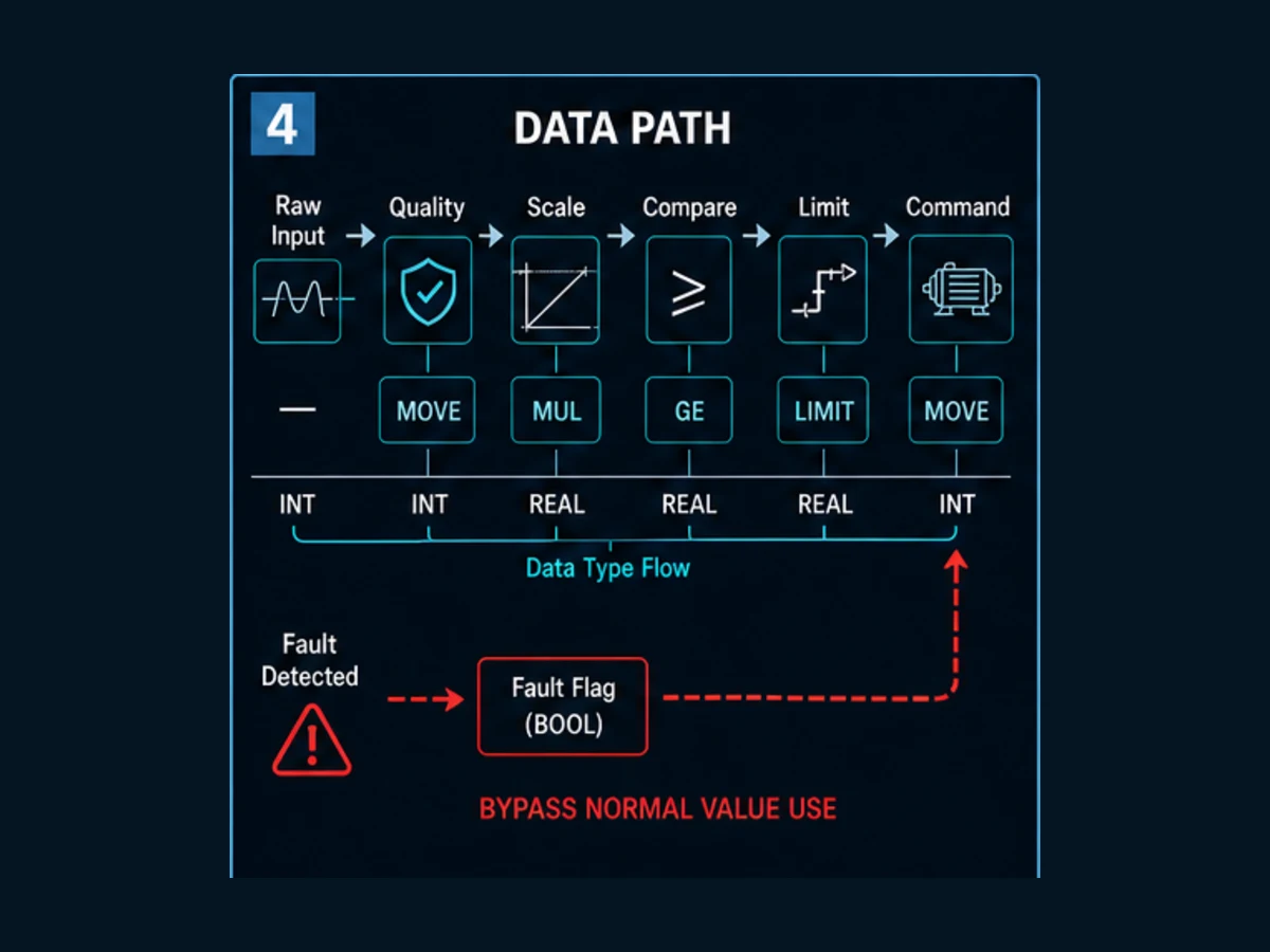
Worked scaling and comparison chain
Suppose a validated analog channel supplies Raw = 18,725 for a documented raw span of 6,242..31,208, representing 0..100.0 psi. A generic implementation can separate normalization, scaling and alarm comparison:
ValidRaw := ChannelGood AND (Raw >= 6242) AND (Raw <= 31208)
Norm     := REAL(Raw - 6242) / REAL(31208 - 6242)
Pressure := Norm * 100.0
High     := ValidRaw AND (Pressure >= 80.0)
For Raw = 18,725, Norm is approximately 0.5 and Pressure approximately 50.0 psi. The numbers are illustrative, not a universal module range. The exact module configuration supplies raw endpoints, under/over-range codes, resolution and diagnostic behavior. Tests should include both endpoints, just-inside and just-outside values, bad quality, integer conversion, overflow, restart and any permitted substitution—not only the midpoint.
| Failure mode | Weak instruction-only design | Bounded design response |
|---|---|---|
| integer division truncates normalization | pressure stays zero over much of the range | convert deliberately before division and test endpoints |
| denominator is zero after bad configuration | runtime fault or undefined result | validate configuration and define an error state before DIV |
| raw value is outside documented range | formula extrapolates a believable number | mark quality bad and apply the approved fail/substitution policy |
REAL becomes NaN or infinity |
comparisons may not behave like ordinary numbers | use platform-supported validity checks and diagnostic status |
| destination is too small | wrap, saturation or fault depends on platform | calculate bounds and test conversion behavior explicitly |
| two tasks write the engineering value | displayed value depends on scheduling | establish one owner and expose source/quality metadata |
Arithmetic Operation Symbols
Mathematical operation symbols enable PLCs to perform calculations required for process control, data analysis, and advanced automation functions that go beyond simple on/off logic.
Addition (ADD) Blocks: Addition combines typed operands and produces a result. Operand count, destination form, enable behavior and overflow reporting are platform-specific; do not assume every ADD exposes a status output.
Subtraction (SUB) Blocks: Subtraction blocks subtract one input value from another and store the result. These blocks are commonly used for calculating differences, remaining quantities, and error values in control applications.
Multiplication (MUL) Blocks: Multiplication blocks multiply input values and store products, enabling calculations for scaling, unit conversions, and complex mathematical relationships in control algorithms.
Division (DIV) Blocks: Division calculates a quotient, but divide-by-zero, integer truncation, sign, overflow and floating-point special values need an explicit policy. Validate the denominator and target type before using the result in control.
Advanced Math Functions: Modern PLCs support trigonometric functions (SIN, COS, TAN), logarithmic functions (LN, LOG), exponential functions, and square root operations for sophisticated calculation requirements.
Data Type Considerations: Mathematical operations must consider data types including integer, floating-point, and double-precision values to ensure calculation accuracy and prevent overflow conditions.
Comparison Operation Symbols
Comparison operations enable programs to make decisions based on numerical relationships between values, providing the logic needed for process control and system monitoring.
Equal (EQU) Blocks: Equality compares typed operands. Exact equality is appropriate for discrete states and some integer values; noisy measurements and calculated floating-point values usually need a tolerance or range defined by the requirement.
Not Equal (NEQ) Blocks: Not equal blocks energize their outputs when input values are different, providing inverse logic for equal comparisons and alarm detection applications.
Greater Than (GRT) Blocks: Greater than comparisons energize outputs when the first input value exceeds the second input value, enabling high-limit detection and process control logic.
Less Than (LES) Blocks: Less than blocks energize outputs when the first input is less than the second input, providing low-limit detection and minimum value enforcement.
Greater Than or Equal (GEQ) and Less Than or Equal (LEQ): These blocks provide inclusive comparisons that are useful for range checking and tolerance-based control applications.
Comparison Applications: Comparison operations are essential for analog process control, alarm detection, quality control, and automated decision-making based on measured values and calculated results.
Data Movement and Conversion Symbols
Data movement and conversion functions enable programs to transfer information between different memory locations and convert data between different formats and types.
Move (MOV) Instructions: Move instructions copy data from source addresses to destination addresses, enabling data transfer between different memory areas and program routines.
Copy (COP) Instructions: Copy instructions transfer blocks of data from source arrays to destination arrays, providing efficient bulk data movement for recipe management and batch operations.
File Fill (FLL) Instructions: Fill instructions load the same value into multiple consecutive memory locations, useful for initializing arrays and clearing data blocks.
Data Conversion Functions: Conversion instructions change data between different formats including integer-to-floating-point, BCD-to-binary, and ASCII-to-numerical conversions required for interfacing with different devices.
Bit Manipulation Instructions: These functions operate on individual bits within data words, enabling packed data handling and efficient memory utilization for digital I/O and status information.
String Manipulation Functions: Text processing functions enable programs to handle alphanumeric data for operator messaging, recipe names, and communication with business systems.
Chapter 5: Advanced Function Block Symbols
Communication Function Symbols
Communication function blocks enable PLCs to exchange data with other devices, systems, and networks, providing the connectivity required for modern integrated automation systems.
Message (MSG) Blocks: Message instructions enable communication with other PLCs, operator interfaces, and computer systems using various protocols including Ethernet/IP, Modbus, and proprietary communication methods.
Serial Communication Blocks: These functions handle RS-232, RS-485, and other serial communication protocols for interfacing with older equipment, instruments, and specialized devices that don't support network communication.
Network Read/Write Functions: Dedicated network functions optimize data exchange with other network devices, providing efficient methods for sharing real-time process data and status information.
Protocol-Specific Blocks: Many PLCs provide function blocks optimized for specific protocols including Profinet, DeviceNet, Foundation Fieldbus, and HART communication standards.
Communication Status Monitoring: Communication functions typically provide status outputs indicating communication success, failure, or progress, enabling programs to handle communication errors appropriately.
Data Formatting Functions: Communication often requires data format conversion between different device requirements, including byte swapping, bit ordering, and protocol-specific formatting.
Process Control Function Symbols
Advanced process control functions provide sophisticated algorithms for precise control of continuous processes, enabling automated systems to maintain optimal performance.
PID Control Blocks: Proportional-Integral-Derivative control blocks implement closed-loop control algorithms for temperature, pressure, flow, level, and other continuous process variables.
Lead/Lag Compensation Blocks: These advanced control blocks provide dynamic compensation for process delays and response characteristics, improving control loop performance.
Dead Time Compensation: Dead time blocks compensate for delays in process response, enabling more aggressive control tuning and better disturbance rejection.
Cascade Control Functions: Cascade control blocks implement multi-loop control strategies where one controller's output provides the setpoint for another controller, improving control of complex processes.
Feedforward Control Blocks: These functions provide predictive control actions based on measured disturbances, enabling faster response to process upsets.
Statistical Process Control: SPC functions calculate control limits, capability indices, and trend analysis for quality control and process optimization applications.
Safety and Diagnostic Symbols
Safety and diagnostic function blocks provide the monitoring, protection, and analysis capabilities required for safe and reliable automated system operation.
Safety-Related Instructions: Safety PLC platforms may provide certified instructions for approved safety architectures. A block name or symbol alone does not create a safety function: hardware, wiring, logic, signatures, verification and validation must follow the selected platform manual and the approved safety lifecycle.
Diagnostic Data Collection: Diagnostic functions monitor system health parameters including scan times, memory usage, communication status, and I/O module health.
Alarm Management Blocks: Alarm functions detect abnormal conditions, prioritize alarms, track acknowledgment status, and manage alarm suppression during startup and shutdown operations.
Equipment Protection Functions: These blocks monitor equipment operating parameters and automatically shut down or reduce loading when conditions exceed safe operating limits.
Fault Detection and Isolation: Advanced diagnostic functions automatically identify and isolate faults to minimize system disruption and provide specific fault information for maintenance personnel.
Predictive Maintenance Functions: These blocks analyze equipment performance trends to predict maintenance requirements before failures occur, reducing unplanned downtime and maintenance costs.
Vendor ladder instruction dialect map
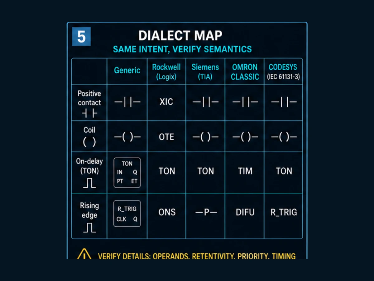
Use the generic column to describe intent, then verify the selected product family. “Omron” is not one dialect: classic CP/CJ/CS projects and NJ/NX Sysmac projects expose different data and instruction models. “Siemens” may mean current TIA Portal LAD or a migrated Classic project. Rockwell Logix is not SLC/MicroLogix syntax. CODESYS-based products can add target-specific libraries on top of the common runtime environment.
| Intent | Generic / IEC-style | Rockwell Logix | Siemens TIA Portal LAD | Omron classic CP/CJ/CS | Omron NJ/NX Sysmac or CODESYS-style | Migration trap |
|---|---|---|---|---|---|---|
| test true | positive contact | XIC | NO contact | LD/contact | contact | tag polarity and input mapping are outside the symbol |
| test false | negated contact | XIO | NC contact | LD NOT/contact | negated contact | XIO means examine false, not “field device is NC” |
| write rung state | ordinary coil | OTE | assignment coil | OUT | coil/assignment | duplicate writers and task order can change final state |
| set state | set/latch | OTL | set coil | SET | set coil | retention across restart/download is separate from set/reset logic |
| reset state | reset/unlatch | OTU | reset coil | RSET | reset coil | simultaneous set/reset priority differs by construct |
| rising edge | R_TRIG or positive edge | ONS/OSR depending on context | positive signal edge | DIFU | R_TRIG / edge contact | storage is implicit, explicit or instance-owned depending on platform |
| on delay | TON | TON structure | IEC TON instance | TIM/TIMX family | TON instance | preset representation, instance data and reset differ |
| up count | CTU | CTU structure | IEC CTU instance | CNT/CNTX family | CTU instance | edge detection, limits and count representation differ |
| equal compare | EQ / = |
EQU | ==/compare box |
CMP/equality family | EQ / typed compare | signedness, width, strings and floating values matter |
| move value | MOVE | MOV/COP depending on task | MOVE | MOV family | MOVE | copy length, overlap and atomicity are not implied by “move” |
| block call | FB/POU call | AOI or routine call depending on design | FB/FC call | function/instruction call | FB/POU instance | a stateful block needs an independent instance identity |
| asynchronous exchange | request block | MSG | communication instruction/FB | protocol instruction | vendor/library FB | trigger pulse, busy ownership, timeout and recovery are part of the contract |
The table is intentionally not a syntax converter. For example, Rockwell ONS uses a storage operand in ladder; an IEC R_TRIG is a function-block instance with prior-clock state; a classic Omron DIFU belongs to a different programming family. All can express a rising-event intent, but replacing the symbol without testing first-call and restart behavior is unsafe migration practice.
Scan-by-scan worked instruction example
Consider a conveyor that should count one accepted product per sensor rising edge, wait 500 ms after the fifth product, then request a diverter only while feedback quality is good. A sound instruction chain separates the raw input, qualified edge, counter state, timer state, comparison and output arbitration:
Network 1: ProductValid := ProductSensor AND SensorQualityGood
Network 2: ProductPulse := RISING_EDGE(ProductValid)
Network 3: CTU_Batch(CU := ProductPulse, R := ResetBatch, PV := 5)
Network 4: TON_Diverter(IN := CTU_Batch.Q, PT := T#500ms)
Network 5: DiverterRequest := AutoMode AND TON_Diverter.Q AND FeedbackQualityGood
Network 6: BatchComplete := CTU_Batch.Q
This pseudocode is behavioral. On an actual platform, ProductPulse, the edge instance, counter instance, timer instance and outputs may be represented differently. The critical ownership rules are stable: one sensor edge feeds one counter call, each stateful block has one instance, reset is explicit, and DiverterRequest has one writer.
| Execution | ProductValid before call | ProductPulse | Counter CV/Q | Timer ET/Q | DiverterRequest |
|---|---|---|---|---|---|
| startup, sensor clear | 0 | 0 | 0 / 0 | 0 / 0 | 0 |
| first rising edge | 1 after 0 | 1 for one call | 1 / 0 | 0 / 0 | 0 |
| sensor remains high | 1 | 0 | 1 / 0 | 0 / 0 | 0 |
| fifth accepted rising edge | 1 after 0 | 1 | 5 / 1 | timing / 0 | 0 |
| fifth-count state held for 500 ms | 0 or 1 | edge-dependent | 5 / 1 | preset reached / 1 | 1 if mode and quality are good |
| feedback quality fails | unchanged | unchanged | 5 / 1 | reached / 1 | 0 |
| approved reset | any | implementation-dependent | reset value / 0 | reset/disabled | 0 |
Two edge cases deserve explicit tests. First, if the sensor is already true on the first call, does the selected edge instruction emit a pulse or initialize without one? Second, if reset and a new count edge occur in the same execution, which input has priority? Never infer either answer from this generic table.
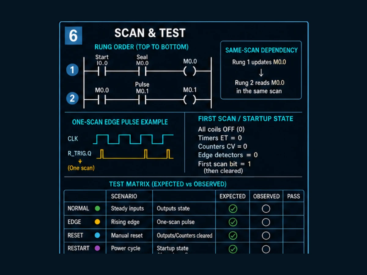
Acceptance tests for an instruction chain
| ID | Test | Expected evidence |
|---|---|---|
| LD-01 | sensor stays false | no pulse; count remains zero |
| LD-02 | one false-to-true transition | exactly one pulse and one count increment |
| LD-03 | sensor stays true for many executions | no additional count |
| LD-04 | sensor bounces under the qualification window | result follows the documented conditioning policy |
| LD-05 | five qualified transitions | counter threshold becomes true once expected count is reached |
| LD-06 | threshold is true for less than 500 ms | timer output remains false |
| LD-07 | threshold remains true through preset | timer output becomes true at the documented boundary |
| LD-08 | feedback quality is bad | diverter request remains false even if timer is done |
| LD-09 | reset while idle | counter and timer return to defined state |
| LD-10 | reset coincident with count edge | observed result matches documented priority |
| LD-11 | restart with sensor false and count below threshold | instance state follows retention/startup specification |
| LD-12 | restart with sensor already true | no unexpected product count unless explicitly required |
Record task period, controller/firmware, tool version, instance path, inputs, expected values, observed values and pass/fail. A screenshot of green logic without that context is not a repeatable test.
Chapter 6: Symbol Programming Best Practices
Program Organization and Documentation
Effective use of Ladder Logic symbols requires systematic organization and comprehensive documentation that enables efficient programming, troubleshooting, and maintenance throughout system lifecycles.
Logical Grouping: Organize ladder logic into functional groups including inputs, main control logic, outputs, alarms, and diagnostics. This organization makes programs easier to understand and maintain.
Consistent Naming Conventions: Establish and maintain consistent naming conventions for addresses, symbols, and functions that clearly indicate their purpose and function within the control system.
Comprehensive Comments: Document the purpose of complex logic sequences, safety interlocks, and unusual programming techniques using clear, concise comments that explain both what the logic does and why it's necessary.
Cross-Reference Documentation: Maintain cross-reference tables that show where specific addresses and functions are used throughout the program, enabling quick identification of all related logic during troubleshooting.
Version Control: Implement systematic version control procedures that track program changes, modification dates, and the reasons for changes to maintain program integrity and enable rollback when necessary.
Standardized Layouts: Develop and follow standardized layouts for common control functions including motor starters, valve controls, and safety interlocks to improve program consistency and reduce development time.
Symbol Selection and Usage Guidelines
Proper symbol selection significantly impacts program readability, troubleshooting efficiency, and long-term maintainability of Ladder Logic programs.
Contact Type Selection: Choose a contact instruction from the Boolean condition the program must test. Then document how that Boolean relates to physical NO/NC wiring, healthy state, de-energized state and diagnostics. Do not select a normally-closed-style instruction merely because the field device is a stop or safety input.
Output Strategy: Use an ordinary coil when the destination should equal the rung result on every intended execution. Use set/reset state only when the requirement defines who sets it, who resets it, simultaneous priority and restart behavior. Prefer an edge detector feeding a named action over assuming a vendor's “one-shot coil” exists or has portable semantics.
Timer and Counter Application: Select from the physical time or event requirement, then allocate one intentional instance per independent behavior. Correct state ownership and tested reset semantics matter more than saving a few bytes of controller memory.
Function Block Usage: Use function blocks for complex mathematical operations, communication, and advanced control algorithms while maintaining clear interfaces and error handling.
Data-Type Discipline: Use types that represent the required range, precision, unit and interface. Review memory and execution performance from measured controller data; do not pack or alias values in ways that make diagnostics, atomicity or type safety worse without a demonstrated constraint.
Error Handling: Implement appropriate error handling for mathematical operations, communication functions, and other operations that might fail, ensuring safe system behavior under all conditions.
Troubleshooting and Maintenance Strategies
Understanding Ladder Logic symbols enables effective troubleshooting strategies that quickly identify and resolve control system problems.
Systematic Diagnosis: Follow logical troubleshooting procedures that start with understanding the intended operation, identifying symptoms, and systematically checking conditions that might prevent proper operation.
Online Monitoring: Use PLC programming software online monitoring capabilities to observe symbol states in real-time, enabling quick identification of logic paths that are or are not executing as expected.
Force Functions: Follow the site's approved force procedure, authorization and removal checks. A force can bypass normal program intent; use it only with the equipment in a controlled condition and never treat a standard force as a safety-test method.
Historical Data Analysis: Use data logging and historical trending capabilities to identify intermittent problems and system performance degradation that might not be apparent during normal monitoring.
Documentation Updates: Maintain current documentation including logic changes, parameter modifications, and operational procedures to ensure accurate troubleshooting information.
Preventive Maintenance: Implement systematic preventive maintenance procedures for programs including backup verification, memory usage monitoring, and performance analysis to prevent problems before they affect operations.
Frequently asked questions
What are the most common PLC ladder logic instructions?
The transferable core is positive and negated contacts, ordinary/set/reset coils, rising and falling edge detection, TON/TOF/pulse timers, CTU/CTD counters, equality and range compares, arithmetic, move/copy, selection/limit, block calls and program-control operations. A real controller adds platform-, CPU- and library-specific instructions. Learn each operation's read, write, state and error contract instead of memorizing a universal list that does not exist.
Is a normally closed ladder contact the same as a normally closed field switch?
No. A negated ladder contact usually tests whether a Boolean operand is false. A physical NC switch describes electrical state in a defined unactuated condition. Wiring, input-module interpretation, tag naming and software logic connect those layers. A slash in ladder does not prove de-energize-to-trip design or make a standard circuit safety-rated.
What do XIC and XIO mean in Rockwell ladder logic?
XIC examines whether its operand is true and XIO examines whether its operand is false in Logix terminology. They are Boolean tests, not instructions that identify the physical field contact type. Confirm the current Logix help for supported operands and controller behavior, and use a tag name that explains the signal meaning.
Are TON and CTU instructions identical on every PLC?
No. The generic intent is similar, but interface, instance storage, preset representation, elapsed/current-value type, reset behavior, retentivity, status members, overflow and restart semantics can differ. Even one vendor may have classic and current families. Translate the state machine and acceptance tests, not only the mnemonic.
Why does my PLC counter increment more than once?
First determine whether the selected counter counts a level or a qualifying edge and whether the signal falls between events. Then inspect sensor bounce, input filtering, task frequency, duplicated counter calls, reused instances and HMI or simulation writes. A time history of raw input, conditioned input, count pulse and current value is more useful than one online screenshot.
Can two ladder coils write the same PLC tag?
Many environments allow more than one writer, but the final value can then depend on task, program and rung execution order or on instruction type. Cross-reference the destination, include HMI/communication/force paths, and prefer one output-arbitration owner. If multiple writers are deliberate, document precedence and test every competing condition.
What happens to an instruction when its rung is false?
It depends on the instruction and platform. An ordinary coil commonly writes false; a set coil may do nothing; a TON may reset or update its state; a called block may receive EN = FALSE; and skipped logic may not execute at all. “False rung,” “disabled call” and “not called” are distinct conditions that require the exact instruction reference.
Can I put functions and function blocks inside ladder logic?
Yes on many platforms. Ladder networks can call typed functions, stateful function blocks, vendor instructions, AOIs or library blocks where supported. A stateful block needs a deliberate instance, a clear interface, error handling and defined behavior when disabled or skipped. The graphical call does not remove normal software design responsibilities.
Is a ladder instruction set portable between Siemens, Rockwell, Omron and CODESYS?
The requirement and generic behavior are portable; project syntax and semantics are not automatically portable. Map each instruction family, data type, instance, task, reset, retention and diagnostic behavior to the target manual. Compile and run the same normal, edge, fault and restart tests on the target runtime before accepting the migration.
How should I test ladder logic instructions without a real PLC?
Use a simulator or isolated training runtime to verify Boolean paths, time histories, edge cases, type boundaries, reset and restart behavior. Record the exact runtime and expected-versus-observed trace. Simulation cannot prove physical I/O, electrical noise, fieldbus timing, motion, process response or a safety function; those require the appropriate hardware and site validation.
Conclusion: Mastering Ladder Logic Symbols for Programming Excellence
Ladder Logic symbols provide the visual vocabulary that enables effective communication between programmers, technicians, and control systems. Mastering these symbols is essential for anyone working with PLCs, from entry-level technicians learning their first programming concepts to experienced engineers designing sophisticated control systems.
The comprehensive understanding of symbols presented in this guide provides the foundation for reading, creating, and maintaining Ladder Logic programs that control the automated systems powering modern manufacturing. Each symbol category—from basic contacts and coils to advanced function blocks—contributes to the complete toolkit needed for effective industrial control programming.
Remember that symbols are tools for implementing control strategies, not ends in themselves. The real value lies in understanding how to combine symbols effectively to create control logic that meets application requirements while maintaining safety, reliability, and maintainability throughout system lifecycles.
Effective use of Ladder Logic symbols requires balancing functionality with simplicity, leveraging advanced capabilities when they add value while maintaining program clarity for future maintenance and modification. The best programs use symbols efficiently and consistently to create control logic that performs reliably while remaining understandable to others.
Continue developing your symbol knowledge through hands-on practice, formal training, and exposure to different applications and programming approaches. The investment in mastering Ladder Logic symbols will provide career-long benefits through improved programming efficiency, faster troubleshooting capabilities, and enhanced ability to create control systems that meet demanding industrial requirements.
The future of industrial automation continues to build on the foundation of Ladder Logic programming, making symbol mastery a valuable and enduring skill that opens doors to rewarding careers in industrial automation and control systems engineering.
Primary Sources and Scope
This guide and downloadable chart were reviewed on August 31, 2026 against the following primary documentation:
- IEC 61131-3:2025, Edition 4 — current syntax and semantics boundary for LD, FBD and ST, with SFC structuring elements.
- PLCopen Logic — shared IEC programming and reusable-software context.
- Rockwell Automation Studio 5000 Logix Designer v38 help — current online instruction categories and per-instruction help.
- Rockwell Logix 5000 General Instructions reference — general instruction behavior and the controller/instruction locator boundary.
- Siemens S7-1200 system manual — current CPU, programming and instruction context for the S7-1200 family.
- Siemens S7-1200/1500 programming guideline — block, instance, data and programming-style guidance.
- CODESYS Ladder and processing order — current ladder editor and version-specific network-order boundary.
- Beckhoff TwinCAT 3 Ladder Diagram — TwinCAT Ladder editor and migration context.
- Omron NJ/NX Instructions Reference Manual W502 — typed Sysmac instruction interfaces and unit-version restrictions.
- Schneider Electric Machine Expert V2.2 FBD/LD networks — contacts, coils, networks, branches and mixed FBD/LD behavior.
- Mitsubishi GX Works3 Operating Manual — current ladder creation, editing and conversion workflow.
- OSHA 29 CFR 1910.147 — US general-industry hazardous-energy-control boundary relevant to online diagnosis; other jurisdictions may differ.
The chart and generated figures are original platform-neutral learning aids, not reproductions of an IEC standard or vendor editor. Six responsive technical panels cover instruction families, field/tag/contact layers, stateful traces, numeric data flow, dialect mapping and scan/test evidence. The retained master is assets/editorial-image-sources/2026/plc-ladder-logic-instructions/plc-ladder-logic-instructions-six-panel-source.png; responsive derivatives are reproducible with scripts/generate-plc-ladder-instruction-images.sh.
Timer reset behavior, retentivity, edge storage, execution order, data conversion, communication state, duplicate-output behavior and online changes must be verified for the selected CPU, engineering software, firmware, task configuration and application. This page teaches a comparison method; it is not a substitute for the approved project manual set, risk assessment or commissioning procedure.