Emergency Stop, Safety Relay and PLC Interface Guide
Design the boundary between an emergency-stop device, safety relay, final elements and standard PLC diagnostics, with reset, EDM, fault-test and validation evidence.
An emergency-stop function is a machine safety function, not a standard ladder rung. A typical chain is an emergency-stop command device, safety-rated input wiring, a safety relay or safety PLC, suitable final switching elements, and the machine's measured hazard response. A standard PLC may read diagnostic status and inhibit its ordinary run request, but that code does not become the safety-rated function.
The safety design must meet the risk assessment, applicable machine-specific standards, required performance level or SIL, response-time calculation, fault detection and validation plan. Do not infer compliance from “dual channel,” a component label or a copied program.
Direct answer: how an emergency stop, safety relay and PLC fit together
The emergency-stop device initiates a demand. A certified safety relay or safety PLC evaluates the configured input channels and faults. Its safety outputs command suitable final elements—such as redundant contactors or a documented drive safety function—which remove or control the hazard according to the selected stop design. External device monitoring (EDM), when required by that architecture, returns final-element feedback to the safety logic before reset is accepted.
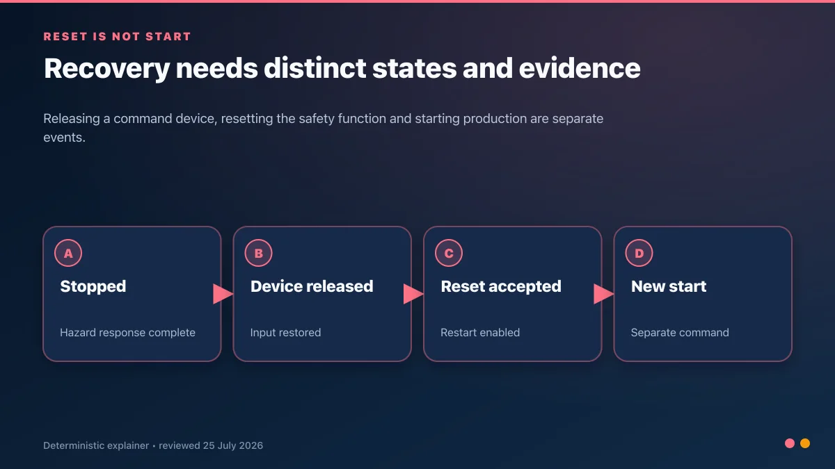
The standard PLC sits beside that credited chain. It can display status, timestamp the event, clear normal run requests and supervise production recovery. It must not be the only path that removes the hazard unless the PLC, I/O, program, communications and final elements are all part of an approved and validated safety-related control system. Releasing the E-stop, resetting the safety logic and issuing a new production start are three separate events.
| Question | Short engineering answer | Evidence required before acceptance |
|---|---|---|
| Can an E-stop go only to a standard PLC input? | Not as the sole credited safety path on an ordinary PLC. A separate safety-rated implementation is required by the risk-assessed design. | approved safety requirements, architecture, component manuals, calculation and validation |
| Does a dual-channel button automatically achieve PL d or PL e? | No. Two channels are only one architectural feature. | category/architecture, reliability data, diagnostics, common-cause measures and full-chain calculation |
| Must every machine use a safety relay? | No. A safety PLC or suitable integrated safety system may perform the logic role. | exact certified use case, lifecycle plan and validation |
| Does an E-stop isolate all hazardous energy? | Not necessarily. Emergency stopping and energy isolation/LOTO are different controls. | energy-control procedure, isolating devices and stored-energy verification |
| May reset restart the machine? | Reset should restore readiness, not create hazardous movement. A separate start and approved recovery sequence are required. | reset-location review, restart specification and observed state tests |
| Can simulation validate the safety function? | No. It can exercise non-safety status and recovery logic only. | installed wiring inspection, fault tests, measured stop response and controlled records |
Terms that must not be treated as synonyms
| Term | Precise role in this guide | Common but unsafe shortcut |
|---|---|---|
| emergency stop | manually initiated complementary protective function intended to avert or reduce an emerging hazard | “the red button makes the whole machine safe” |
| operational stop | normal production stop used by the control sequence | crediting an ordinary stop command as the emergency-stop function |
| energy isolation | disconnection and control of hazardous energy for work in the defined procedure | assuming a dropped contactor equals verified isolation |
| safety relay | safety logic subsystem with documented input, reset, diagnostic and output use cases | assigning the relay's headline rating to the complete machine function |
| safety PLC | programmable safety-related logic system used within its certified hardware/software workflow | treating any PLC with two inputs as a safety PLC |
| EDM / feedback loop | monitoring of selected external final-element state before re-energisation | reading only the relay output LED or standard run feedback |
| reset | deliberate action that permits the safety function to become ready after valid conditions return | using reset as a start command or bypass |
| restart | a separate command and sequence that can reintroduce hazardous motion | retaining the old run request across an E-stop |
| validation | analysis and testing that the installed function meets its safety requirements | pressing each button once on the happy path |

Evidence matrix for a safety review
| Evidence item | What it must identify | Not proved by |
|---|---|---|
| Risk assessment | Hazards, limits, operating modes and risk reduction | “We always use PL d” |
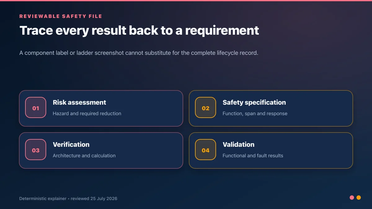
| Safety requirements specification | Function, safe state, reset, span and response time | A ladder screenshot |
| Architecture/calculation | Exact input, logic and output subsystems plus component data | A relay's front-label rating |
| Verification | Wiring, logic, parameters and calculation against the specification | Simulation alone |
| Validation | Functional and fault tests with recorded acceptance results | Pressing one E-stop once |
| Change control | Version, checksum/signature, approvals and retest scope | An undated PDF |
Practice only the standard-PLC status latch and restart inhibit. The simulator cannot design, calculate, emulate or validate the safety-rated emergency-stop function.
This guide explains stop-category context, safety-relay and safety-PLC roles, standard-PLC observation logic, reset boundaries and the evidence to capture during commissioning.
Table of Contents
- The Three Stop Categories
- ISO 13849 Performance Levels — a Quick Primer
- The Safety Relay Between Button and Contactor
- Where the Standard PLC Fits In
- Ladder Logic for the PLC-Side Observation Role
- Safety PLCs: When You Need One
- Dual-Channel Monitoring and Cross-Checking
- Reset Logic — Why Auto-Restart is Forbidden
- Common E-Stop Anti-Patterns
- Worked Conveyor Example
- Commissioning and Documentation
- Frequently Asked Questions
- Sources and Limitations
The Three Stop Categories
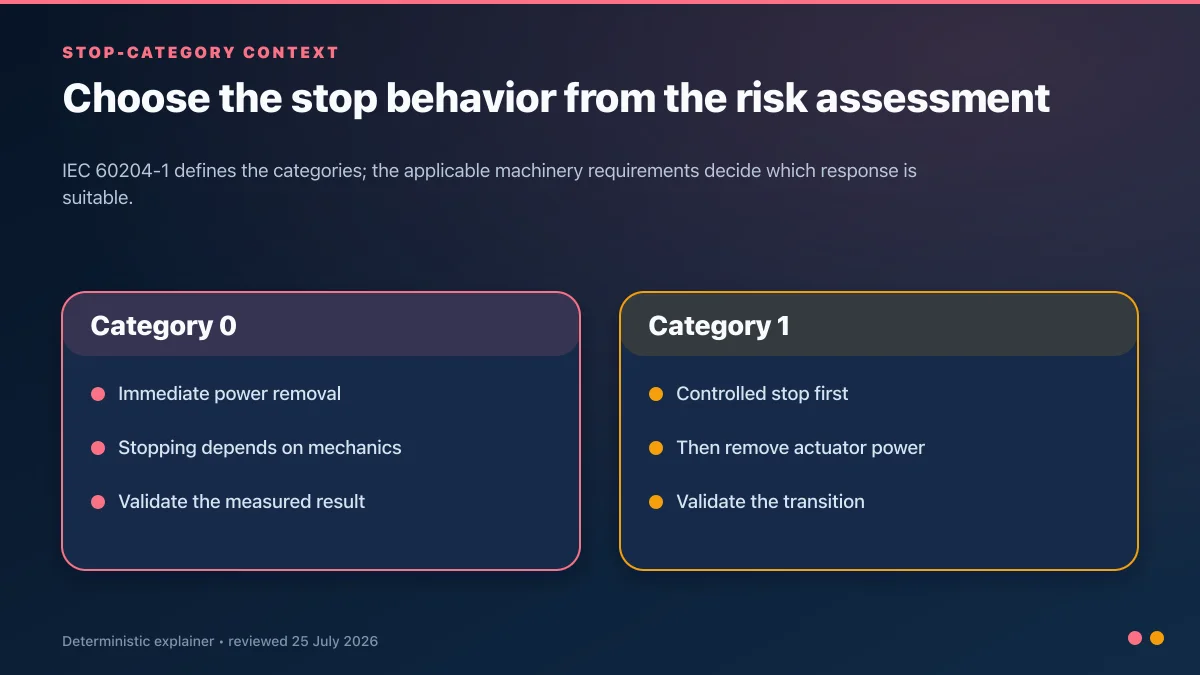
IEC 60204-1 describes three stop categories. The emergency-stop function uses Category 0 or 1 as selected by the risk assessment and applicable machine standard.
Stop Category 0 — stopping by immediate removal of power to the machine actuators. The resulting stopping time depends on inertia, braking and the mechanical system. Immediate power removal is not automatically the shortest or safest stop for every hazard.
Stop Category 1 — controlled stop with power available to achieve the stop, followed by removal of power to the actuators. The safety design must monitor or bound the transition and account for the drive, brake and load.
Stop Category 2 — controlled stop with power left available to the actuators. It is a stop category in IEC 60204-1 but is not used for the emergency-stop function described by ISO 13850.
Do not choose the category from a list of machine examples. Record why the selected stop reduces the relevant risk and validate the measured stop behavior across the operating envelope.
| Stop category | Functional sequence | Power after the stop | Emergency-stop boundary |
|---|---|---|---|
| Category 0 | power to the actuator is removed without using a powered deceleration sequence | removed from the selected actuator path | can be selected when the resulting stop behavior reduces the assessed risk |
| Category 1 | a controlled stop is executed, then power is removed from the actuator | available during the controlled phase, removed afterward | can be selected when controlled deceleration is required and the transition is safety-related |
| Category 2 | controlled stop with power left available | remains available | a stop category, but not the emergency-stop option under ISO 13850 |
Select the stop behavior from the hazard, not from a favorite circuit
Start with the hazardous motion or energy and the machine's safe-state definition. A high-inertia axis may take longer to coast after immediate power removal than it takes to decelerate under a validated drive safety function. A suspended load may need a brake or mechanical restraint. Pneumatic or hydraulic energy may remain after an electrical contactor opens. A connected machine may also create a new hazard if one zone stops while another continues to feed material.
Define the maximum acceptable response and stopping performance in the safety requirements before selecting a relay output arrangement. The final test is the machine response, not the LED response. Measure the relevant stop behavior at the operating conditions identified by the validation plan and retain the raw observation with the test setup, load/state, instrument identity and acceptance result. If a timed Category 1 design is used, prove the behavior for the exact drive, braking, load and fault conditions; a generic timer copied from another machine is not evidence.
ISO 13849 Performance Levels
ISO 13849-1 defines performance levels from PL a through PL e for safety-related parts of control systems. A PL is not a direct injury label, and ISO 13849-1 does not assign the required PL to an application.
Start with the ISO 12100 risk assessment and any applicable Type-C machine standard. Define the safety function and required performance, then design and evaluate the full input–logic–output chain. The achieved PL depends on architecture/category, component reliability data, diagnostic coverage, common-cause measures, mission time and software/systematic requirements.
“Dual channel” alone does not prove PL d or PL e, and a safety PLC is not automatically required by a particular PL. Conversely, a safety relay label does not prove that the installed circuit achieves its headline capability. Document the actual configuration and calculation.
The Safety Relay
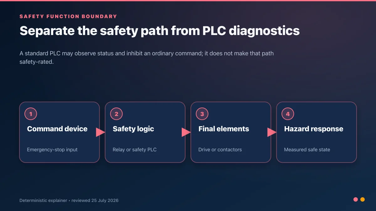
A safety relay is one implementation option between the emergency-stop command device and the final switching elements. A safety PLC, fail-safe I/O or safety-integrated drive may perform some or all of the safety logic. These are not interchangeable without checking the certified application and complete safety-function design.
A safety relay:
- Accepts the supported single- or dual-channel input arrangement shown in its manual
- Detects specified faults such as channel discrepancy or shorts when wired and parameterised accordingly
- Controls safety outputs connected to the selected final switching elements
- Provides monitored manual or automatic start/reset modes where the risk assessment permits
- Supplies safety data and certified use cases needed for the function-level calculation
In the illustrated architecture the safety relay performs the logic portion; the complete function also includes the command device, wiring, final switching elements, actuator/load behavior and validation.
Choosing a safety relay, configurable relay or safety PLC
| Logic option | Strong fit | Engineering burden to control | Do not assume |
|---|---|---|---|
| fixed-function safety relay | one or a few local functions with an exact manual application and modest diagnostics | terminal assignment, start mode, feedback loop, contact ratings, expansions and fault reset | every E-stop circuit wires the same way |
| configurable safety relay | several local functions or zones that benefit from documented configuration and diagnostics | tool/version control, configuration signature, approved function blocks, I/O mapping and change validation | “relay” means there is no safety software lifecycle |
| safety PLC with fail-safe I/O | distributed functions, safe networking, complex zoning, coordinated safety or safe motion | certified hardware/firmware, safety program workflow, signatures, access control, independence and lifecycle records | required PL alone dictates a safety PLC |
| safety-integrated drive function | torque, speed, direction or stopping functions supported by the exact drive and architecture | drive certificate/manual, encoder assumptions, safety parameters, reaction chain and final mechanical response | STO is identical to an emergency stop or to isolation |
Use the least complex architecture that meets the safety requirements and can be maintained correctly through the machine lifecycle. A simple fixed relay can be the best option for one stable function; a programmable system can reduce wiring and improve diagnostics on a larger machine. Complexity is neither automatically safer nor automatically less safe. What matters is whether the exact implementation is within its certified use, calculated for the required performance and validated against the machine response.
How to read an emergency-stop safety-relay wiring diagram
Do not copy terminal numbers from a generic drawing. The Siemens 3SK2 manual, Rockwell Guardmaster GSR manual, Pilz PNOZ manual and Schneider XPSUAF guide each define product-specific sensor supply, channel inputs, reset/start behavior, feedback monitoring, safety outputs and diagnostic indications. Even products from the same family can use different terminals or configuration modes.
| Drawing block to verify | Question for the exact product manual | Evidence to retain |
|---|---|---|
| command device contacts | which contact arrangement and positive-opening device are approved for the intended use? | device part number, contact diagram and inspection record |
| channel supply and returns | does the manual use test outputs, separate sources or a supported cross-short detection method? | as-built terminal schedule and conductor identifiers |
| start/reset circuit | is start automatic, manual or monitored, and what signal transition is required? | configuration position/signature and reset test results |
| EDM / feedback loop | which external contacts must be closed before the relay can reset? | contactor/drive feedback diagram and stuck-feedback test |
| safety outputs | what output type, utilization limits, suppression and expansion rules apply? | load calculation, final-element data and wiring inspection |
| auxiliary output | what exactly does the status signal mean, and is it safety-rated or diagnostic only? | PLC tag contract and HMI wording |
| power and protective bonding | what supply, protection and installation requirements apply? | panel drawing, device data and commissioning measurements |
A two-channel schematic is not proof of two independent fault paths. Route conductors, select contacts, configure test pulses and document exclusions according to the approved design. A field jumper that makes the relay ready can simultaneously defeat the diagnostic assumption on which the calculation depended.
Live mini-lab
Try it: press START, then STOP
A stop-dominant seal-in rung: START latches the motor output through its own contact, and STOP breaks the circuit.
Watch the output lamp: it stays on after START until you press STOP.
Free · no signup to try · runs in your browserOpens plcsimulationsoftware.com — same team
Where the Standard PLC Fits In
A standard (non-safety-rated) PLC has three legitimate roles in an E-stop circuit:
- Observation — read the safety relay's monitoring output (most relays provide one) and reflect the E-stop state in the PLC's logic. Useful for HMI indication, alarm logs, and preventing automatic restart of downstream processes.
- Latching alarms — when the E-stop trips, write a timestamped entry to the alarm buffer, hold the fault state until an operator acknowledges it, and prevent sequences from resuming until acknowledgement is recorded.
- Coordinating ordinary process state — clear standard run requests and place related sequences in a defined recovery state. If the emergency-stop function must span multiple zones, that span belongs in the safety-related design, not only in standard PLC coordination.
The PLC does not:
- Replace the specified safety-related input, logic or output subsystem
- Bypass the validated reset/restart requirements
- Supply the safety response-time or fault-tolerance claim for a non-safety-rated signal path
Code that routes an ordinary motor command through an EStopActive status can improve sequence behavior and diagnostics, but it is still standard control logic unless the whole implementation is safety-rated and validated.
Define a PLC diagnostic signal contract before writing ladder logic
One auxiliary contact can mean “safety outputs energized,” “input healthy,” “relay ready,” “device has power” or a combined status. Those meanings lead to different alarms and recovery rules. Name the PLC tag after the documented state and record its normal polarity, invalid state and source terminal. Do not name every safety-related contact EStop_OK.
| Standard PLC tag example | Source meaning to confirm | Legitimate use | Unsafe inference |
|---|---|---|---|
SafetyOutputsEnergized |
relay auxiliary output follows the safety-output state | sequence inhibit, HMI state, event logging | all command devices and final elements are healthy |
SafetyRelayReady |
logic conditions permit or await a reset/start | maintenance diagnostics | machine is safe to enter |
EStopZone1Demanded |
safety system exposes an interpreted zone demand | alarm localization and production-state reset | the standard bit performed the stop |
K1K2FeedbackClosed |
selected contactor feedback is closed | diagnostic comparison and maintenance trend | power is isolated or zero energy is verified |
SafetySystemFault |
documented combined or specific diagnostic fault | first-out alarm, work-order context | it is safe to force or bypass the faulted channel |
SafetySignatureChanged |
approved platform exposes configuration identity | change-control alarm and audit trail | the new program is validated merely because it compiled |
Keep four state classes separate on the HMI: current demand, safety-system readiness, safety-output state and historical event. Operators need to know whether a red indication means a pressed button, an open channel, an EDM mismatch, a configuration fault or simply outputs awaiting a deliberate reset. Maintenance needs the source identifier and timestamp, not a vague “E-stop fault.”
Ladder Logic for the PLC-Side Observation Role
Here is a platform-neutral observation pattern. Confirm the diagnostic contact polarity and whether it represents “safety function healthy,” “outputs energised” or another state—the meanings are not identical.
| SafetyFunctionHealthy                    EStopActiveStatus |
|---------|/|------------------------------------( )---------|

| EStopActiveStatus                        EStopEventLatched |
|---------| |-----------------------------------(L)----------|

| ResetPB       SafetyFunctionHealthy       EStopEventLatched |
|---| |----------------| |----------------------(U)-----------|
Run this in the simulator — no signup
Reading the rungs:
- Rung 1 translates a positively named diagnostic input into an active-status bit. Confirm whether other safety faults can also make the input false; label the HMI accordingly.
- Rungs 2 and 3 preserve an event for HMI/alarm history until the diagnostic input is healthy and an operator acknowledges it. They do not reset the safety relay or safety PLC.
Display the current safety-system status distinctly from the historical event latch, log transitions with the controller clock quality documented, and inhibit ordinary sequence restart until the approved recovery conditions are met. None of this replaces the safety-related function.
Scan-by-scan behavior of the observation example
Suppose SafetyFunctionHealthy falls during an automatic cycle. On the next standard PLC scan, EStopActiveStatus becomes true and the history latch sets. Ordinary run requests should be cleared or driven to a defined recovery state. The credited hardware/safety logic has already initiated the safety response independently; the standard PLC timing is not part of its claimed reaction time.
When the physical device is released, the diagnostic may remain false because a channel discrepancy, EDM fault or reset condition is still present. If it returns true after the safety-system reset, the history latch remains set until the separate acknowledgement rung is satisfied. A retained production-start request must not silently resume the cycle. The approved start action and permissives create a new run request only after the recovery state is understood.
Test the standard logic with the diagnostic signal changing before, during and after each sequence state; with communication quality invalid; across PLC restart; and with a held reset or start input. These are useful simulator tests because they concern non-safety coordination. They do not validate the safety controller scan, test pulses, final elements or machine stopping performance.
Safety PLCs: When You Need One
Safety PLCs are useful when the validated design benefits from configurable safety logic, distributed fail-safe I/O, zone coordination, safe motion or diagnostics. Required PL alone and a fixed count of safety functions do not determine the architecture.
Examples include Siemens fail-safe CPUs, Rockwell GuardLogix and Pilz safety controllers. Product names, firmware, safety signatures and supported instructions change, so use the current safety manual and certificate for the exact part number. Depending on the platform:
- Safety logic is separated, compiled and identified according to the vendor's safety workflow
- Certified instruction libraries and restricted language features may be provided
- Fail-safe I/O offers configurable discrepancy, test-pulse and fault diagnostics
- The complete application can be evaluated to the required PL/SIL when used inside the certification limits
A safety PLC can directly control suitable fail-safe outputs or drives; an additional safety relay is not universally mandatory. Choose the architecture from the safety requirements, component certificates, maintainability, lifecycle and validation effort—not an unsupported price rule or function-count threshold.
Dual-Channel Monitoring and Cross-Checking
Dual-channel input architectures use two signal paths so specified faults can be detected or tolerated. The exact contact arrangement, test pulses, discrepancy behavior and reset sequence are defined by the safety device and logic manual.
- Discrepancy monitoring. If the channels do not transition as expected, supported logic can latch a fault. Use the configured time from the validated design, not a generic range.
- Short and wire-break diagnostics. Test pulses, separate supplies or supported equivalent/complementary contact arrangements can detect particular faults. Each detects a defined set—not every wiring fault.
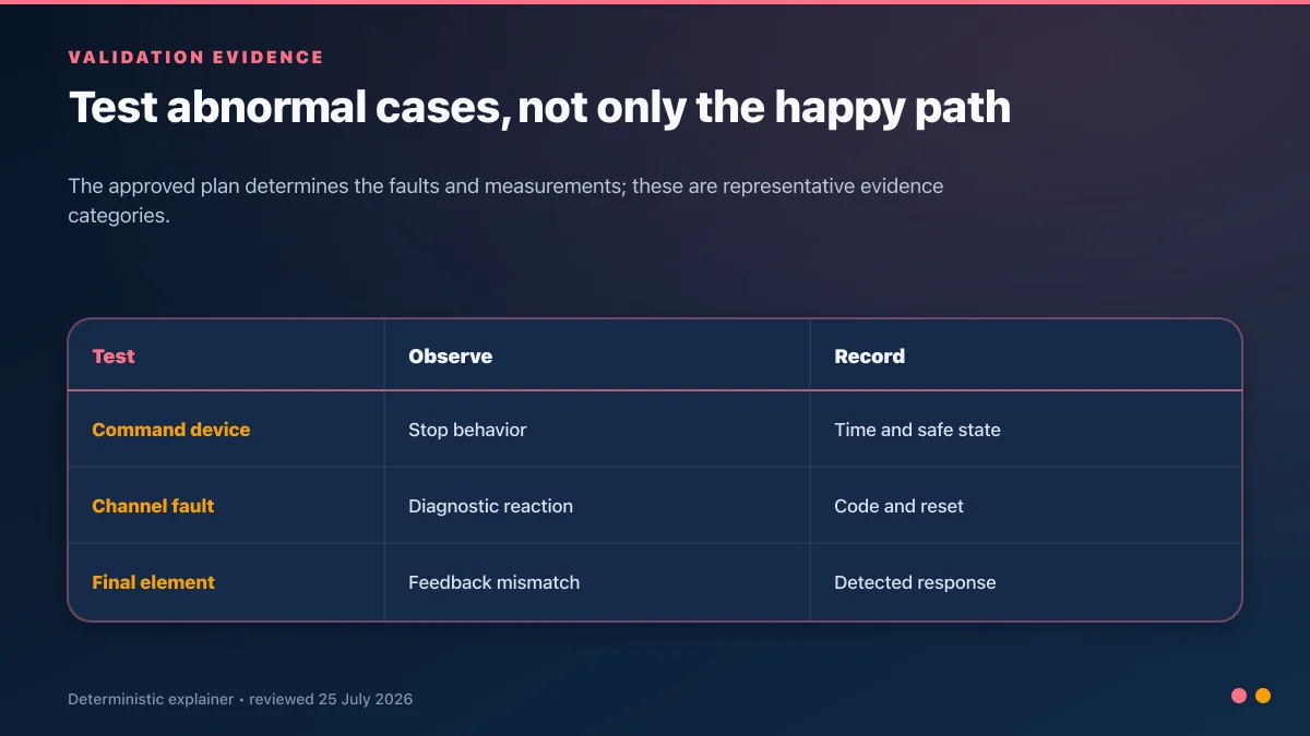
Wire and parameterise the input exactly as shown for the certified application. Then fault-test one open channel, a discrepancy, shorts covered by the diagnostic design and reset behavior, recording the observed state and diagnostic code.
| Controlled test | Expected safety-system observation | Expected machine/result evidence | Reject when |
|---|---|---|---|
| operate each E-stop from every specified mode | both configured channels transition and the function demands the selected stop | safety outputs/final elements change and measured hazard response meets the requirement | any device is outside the function span or response exceeds its limit |
| open channel 1 only | configured discrepancy or channel fault prevents readiness as designed | machine remains or moves to the specified safe state; fault is identifiable | the relay resets with the single fault present when the design says it must detect it |
| open channel 2 only | symmetric or otherwise documented diagnostic behavior | recorded result traces the exact channel | only one channel was ever fault-tested |
| create the supported cross-short fault | test-pulse/cross-circuit diagnostic reacts according to the exact manual | output and reset behavior match the safety requirements | a short leaves an undetected ready state contrary to the design assumption |
| hold EDM feedback in the “closed” state | feedback inconsistency blocks reset or readiness | final-element fault is shown and no restart is possible | feedback is bypassed, ignored or only alarmed by the standard PLC |
| hold EDM feedback in the “open” state | reset/start remains blocked | diagnostic points to final-element/feedback path | repeated reset attempts can re-energize outputs |
| press reset while a demand/fault remains | reset is rejected | no hazardous movement or readiness transition | reset masks the cause or acts as a start |
| remove and restore control power | system enters the specified startup state | no automatic hazardous restart; configuration identity remains controlled | prior run state recreates motion without the approved start sequence |
Only inject faults under an approved, risk-controlled validation procedure by competent personnel. Do not short safety terminals or defeat guards on a production machine merely to follow an online checklist. Many tests belong in a controlled commissioning state with the hazardous energy managed and the method approved in advance.
Reset Logic — Why Auto-Restart is Forbidden
Releasing the emergency-stop command device must not by itself restart the machine. Reset restores the ability to start; it is not a start command. The required reset location, visibility, monitored edge and separate start action come from the applicable standards and risk assessment.
One common sequence is:
- E-stop physical button rotated (or pulled) back to its armed position — the mushroom "unlocks."
- Both safety relay input channels read "safe" again.
- The operator performs the configured reset action with the safeguarded area checked as required.
- The safety logic accepts the reset only if all monitored conditions and feedback are valid.
- Any auxiliary interlocks (door closed, guard in place) are also satisfied.
- Only then can the machine's normal start sequence run — itself requiring a separate Start press per the three-wire control principle.
The standard PLC should clear ordinary run requests and require the approved new-start sequence after recovery. A separate HMI acknowledgement may be useful for process state or alarm history, but it is not universally required and must not reset or bypass the safety function.
| Recovery state | Physical/safety condition | Standard PLC behavior | Transition evidence |
|---|---|---|---|
| demand active | command device actuated or safety function otherwise demanded | clear ordinary run requests, latch event, show exact zone/source if available | event time and safety-output/final-element state |
| device released, not ready | input has returned but discrepancy, EDM, configuration or reset condition remains | keep sequence inhibited; show “not ready” separately from “button pressed” | diagnostic code and unresolved condition |
| ready for reset | all conditions defined by the safety design are valid | permit only approved non-safety indications; do not manufacture a reset pulse | safety-system readiness indication and area check procedure |
| safety reset accepted | safety logic is ready and outputs are in their designed state | remain in production recovery; old start request stays cleared | reset event, output state and retained fault history |
| ready for separate start | process permissives and restart conditions are valid | accept a new deliberate start through normal control logic | operator command, permissive snapshot and state transition |
The reset device location matters because the person resetting may need a clear view of the protected area and must not be able to reach into it while actuating reset. For large or obscured zones, the approved design may require additional measures. This is a risk-assessment and machine-design decision—not something a generic HMI button can resolve.
Common E-stop anti-patterns
- Standard PLC logic presented as safety-rated. Certification and validation apply to the complete input–logic–output function, not the variable name.
- Undefined safe state. “Motor off” may not address gravity, stored pneumatic/hydraulic energy, coasting or connected equipment.
- PL selected by habit. Determine the required performance from the risk assessment and machine-specific standard.
- Channel count used as proof. Two wires or two contacts do not establish diagnostic coverage, common-cause measures or achieved PL.
- Diagnostic timing changed to hide a fault. Parameter changes must follow change control, the certified range and revalidation.
- Reset without visibility or zone analysis. A reset can be shared only when the safety requirements show that its location and span are appropriate.
- Restart state retained. Safety reset, communications recovery or power restoration must not create unintended movement.
- Ambiguous monitoring signal. Distinguish command-device state, safety-function state, safety-output state and final-element feedback on the HMI.
- No final switching-element feedback. Where required, monitor contactors, brakes or drive status and test stuck/welded feedback behavior.
- Happy-path-only commissioning. Execute the approved functional and fault-injection plan under controlled conditions, including every command device, channel fault, reset case and measured stop-time requirement.
Troubleshoot a safety relay without defeating it
Begin from documented states: exact device part number, firmware/configuration where applicable, supply state, LED/fault code, both input channels, reset/start circuit, EDM loop, safety outputs and final-element feedback. Preserve the first fault indication before cycling power. A power cycle may erase the diagnostic evidence without fixing the cause.
| Symptom | Evidence to capture first | Plausible causes to check in the manual | Unsafe response |
|---|---|---|---|
| relay will not reset | input LEDs/status, reset transition, EDM state, fault code | one channel still open, channel discrepancy, wrong reset mode, EDM open, configuration fault | bridge the reset or EDM terminals |
| one channel changes, the other does not | device contact state, terminal voltage under approved method, conductor identity | failed contact, broken conductor, terminal fault, wiring mismatch | parallel the bad channel into the good one |
| resets only after power cycle | pre-cycle diagnostic code and sequence of states | latched fault, invalid start transition, supply disturbance, configuration behavior | adopt power cycling as the operating procedure |
| outputs energize but actuator does not enable | relay outputs, downstream coil/drive input, feedback, protection state | output load/wiring fault, final-element failure, separate permissive | assume the relay proves the entire output path |
| output drops intermittently | timestamped code, both channels, supply quality, vibration and terminal evidence | loose wiring, supply dip, test-pulse incompatibility, contact bounce, environmental issue | extend discrepancy time until the symptom disappears |
| PLC says E-stop while relay appears ready | auxiliary-output definition, polarity, PLC input quality, timestamp alignment | wrong tag meaning, failed auxiliary contact, wiring/input fault, stale network state | rename or invert the bit without verifying the source |
| contactor feedback prevents reset | K1/K2 auxiliary state and mechanical/main-contact inspection under safe procedure | welded/stuck contactor, wrong auxiliary contact, feedback wiring failure | bypass EDM to restore production |
| fault returns after maintenance | as-left wiring, part/configuration identity, change record, validation scope | wrong replacement, terminal transposition, altered setting, incomplete revalidation | treat matching form factor as compatibility proof |
If the manual identifies a fault that requires replacement, configuration recovery or qualified service, follow that path. Do not force a safety input, edit a certified application outside change control, or hide a persistent fault behind a standard PLC alarm delay.
Worked example: conveyor E-stop, safety relay and PLC diagnostics
Consider a guarded training conveyor with two emergency-stop stations, a motor starter, a standard PLC and an HMI. The risk assessment and safety requirements—not this example—must define the hazards, required performance, function span, stop category, maximum stopping behavior and access controls for a real machine.
In the conceptual architecture, the two command devices form supported safety input circuits into a selected safety relay. The relay's safety outputs control two suitable final switching elements or the documented drive safety inputs. Their monitored auxiliary signals return through the EDM arrangement required by the manual. A separate diagnostic output goes to the standard PLC. The ordinary PLC run output is not in the credited safety path and cannot hold the final elements on after a safety demand.
The PLC maintains three distinct values: current safety-system status, a latched E-stop event and the conveyor production-recovery state. An E-stop clears the normal run request and moves the sequence to RecoveryRequired. Releasing the button does not recreate the request. Once the safety system accepts its independent reset, the PLC still waits for a separate production acknowledgement/start according to the approved sequence.
| Test case | Safety-related expected result | Standard-control expected result | Evidence pack |
|---|---|---|---|
| operate station A while running | selected stop occurs through the safety path; final elements reach specified state | current status changes, event latches, run request clears | station ID, channel/output states, measured machine response and timestamp |
| operate station B while stopped | function remains demanded and restart is prevented | HMI identifies demand without falsely claiming motion was stopped | device and zone state, reset rejection and HMI capture |
| release station A | release alone does not cause hazardous restart | event remains latched and sequence remains in recovery | state transition record and absence of new run command |
| reset with K1 feedback invalid | safety reset is rejected as designed | PLC reports final-element/EDM context if exposed | feedback inspection, device diagnostic and rejection result |
| reset healthy function | safety system becomes ready according to its configuration | PLC remains stopped until separate production start | reset event and separate start event |
| interrupt one configured channel | specified diagnostic/fault response occurs | exact available diagnostic is logged; no bypass command is generated | channel, code, safety-output state and restoration procedure |
| restore controller power | approved startup behavior occurs without automatic hazardous motion | old run request remains cleared and state is understandable | startup trace, retained/non-retained tags and operator action |
This worked example deliberately stops at the interface contract. It does not provide terminal-to-terminal wiring, a PL/SIL calculation, contactor selection or a universal reset circuit. Those decisions depend on the exact command device, safety relay, final elements, drive, machine, standards and jurisdiction. The useful transferable lesson is the separation of the credited safety chain from diagnostic PLC logic and the traceability of every test to a requirement.
Run the non-safety PLC recovery-state example in the browser. Use it to test status latching, run-request clearing and separate restart behavior only. It cannot emulate the safety relay, prove wiring diagnostics, calculate PL/SIL or validate the conveyor.
Commissioning and Documentation
A reviewable emergency-stop function normally needs, at minimum:
- Risk assessment per ISO 12100 — identifies the hazards, the required PL per function, and the rationale.
- Safety requirements specification — defines the function, safe state, initiating devices, span, reset/restart behavior, fault reaction and maximum response time.
- Architecture and calculation per the selected standard — identifies exact parts, safety data, assumptions, diagnostic coverage, common-cause measures and mission time. IFA's SISTEMA or another suitable tool can support a calculation but does not replace engineering review.
- Verification and validation plan/results — traces each requirement to inspection, functional test, fault test and measured result.
- Configuration and change record — captures drawings, software safety signature/checksum, parameters, versions, approvals and retest scope.
Keep the records with the machine technical file and update them after safety-related changes. Evidence is part of lifecycle control, not paperwork added after commissioning.
Commission from requirements to recorded result
Review the safety requirements before energisation and trace each function to a drawing, component data set, calculation and test. Inspect the as-built circuit against the controlled drawing. Confirm part numbers and versions, configuration switch positions or signatures, conductor identity, final-element feedback and protective measures. Resolve discrepancies before relying on functional testing.
Execute normal-state, demand, fault and recovery tests under the approved plan. Record what the machine actually did—not merely “pass.” For a stopping requirement, retain the defined operating condition and measured result. For a diagnostic requirement, retain the injected fault, device code, output state and reset behavior. For a configuration requirement, retain the safety signature/checksum and approved version. A screenshot without context is not a validation record.
After a safety-related change, define the affected requirements and regression scope before returning the machine to service. A replaced contactor, revised drive parameter, relocated E-stop, new PLC/HMI diagnostic, safety-logic edit or firmware change can alter the interface or evidence. Change control should state who approved the change, what was retested, what remained unaffected and which as-left files now define the machine.
Key Takeaways
- A standard PLC status rung is not the emergency-stop safety function.
- ISO 13850 emergency-stop behavior uses Category 0 or Category 1; Category 2 is outside that emergency-stop definition.
- ISO 13849-1 performance levels flow from a risk assessment, not a guess.
- Channel architecture, diagnostics and achieved PL must be calculated for the complete function; channel count alone proves nothing.
- Releasing or resetting the emergency-stop function must not itself command an unintended restart.
- Verification, validation and controlled configuration records are required evidence for lifecycle safety.
Frequently asked questions
What does a safety relay do in an emergency-stop circuit?
A safety relay evaluates the supported emergency-stop input arrangement, detects the faults documented for that configuration, controls safety outputs and enforces the configured start/reset and feedback behavior. It is the logic subsystem in a common input–logic–output safety chain. The relay alone does not establish the achieved PL or SIL: the command device, wiring, outputs, final elements, reliability data, diagnostics, common-cause measures and machine response all belong to the complete function.
Can an emergency stop be wired only to a standard PLC input?
An auxiliary safety-system status may be wired to a standard PLC for indication, alarms and production recovery. An ordinary PLC input, ordinary program and ordinary output should not be treated as the sole credited emergency-stop path. If programmable logic performs the safety function, it must be implemented inside the approved safety-related controller, I/O, communications, software and validation lifecycle for that machine.
How do I wire a dual-channel E-stop to a safety relay?
Use the exact command-device and safety-relay manuals for the selected part numbers and certified application. Confirm the supported contact arrangement, channel/test supplies, input terminals, cross-short diagnostic method, reset/start circuit, EDM loop, output loads and protective requirements. There is no safe universal terminal diagram: even related relay models use different supplies, terminals and configuration modes. Inspect the as-built circuit and fault-test the documented diagnostics under an approved plan.
Why will a safety relay not reset after the E-stop is released?
Releasing the command device restores only one condition. A channel may still be open or discrepant, the reset transition may not match the configured mode, EDM feedback may show a final element in the wrong state, a cross-circuit fault may be latched, supply/configuration may be invalid, or another device in the function span may remain demanded. Preserve the fault code and input/output states, then follow the exact manual. Never bridge reset, channels or EDM to make the relay ready.
What is EDM on a safety relay?
EDM means external device monitoring. In a common architecture, auxiliary contacts or documented status from the selected contactors or drive return to the safety logic so it can check the external output path before accepting reset or re-energisation. EDM does not prove zero energy, and a generic motor-running contact is not automatically suitable. The exact feedback devices, contact state, wiring and diagnostic expectation belong in the approved design and product manual.
What is the difference between emergency-stop Category 0 and Category 1?
Category 0 removes actuator power without using a powered controlled-stop phase. Category 1 performs a controlled stop and then removes actuator power. Either can be used for an emergency-stop function when selected by the risk assessment and applicable machinery requirements. Category 2 leaves actuator power available and is not the emergency-stop option described by ISO 13850. Validate the actual machine stopping behavior; do not choose from labels alone.
Does pressing an emergency stop replace lockout/tagout?
No. Emergency stopping and hazardous-energy isolation address different situations. An E-stop may leave electrical, pneumatic, hydraulic, gravitational, thermal or stored energy present, and it may depend on control components that can fail or be reset. For servicing within OSHA 1910.147's scope, use the required energy-control procedure, isolating devices, locks/tags and verification. Site and jurisdictional procedures may impose additional requirements.
Should emergency-stop contacts be normally closed?
Many hardwired E-stop applications use normally closed, direct-opening contacts in supported monitored circuits so an open conductor can lead to a demand or fault instead of appearing as a healthy command. That rule of thumb is not a complete wiring design. Use the command-device contact diagram and safety-relay manual, confirm positive/direct opening where required, check dual-channel fault coverage and validate the installed circuit. Do not infer achieved PL from contact polarity alone.
When should I choose a safety PLC instead of a safety relay?
Choose from the safety requirements and lifecycle, not a fixed function count or PL threshold. A fixed relay is often maintainable for one or a few local functions. A configurable relay or safety PLC can suit distributed I/O, multiple zones, safe networking, safe motion or complex diagnostics. The programmable option adds controlled tools, versions, safety signatures, access, verification and regression testing. Either architecture must remain inside its certified use and meet the complete function calculation and validation.
Can a PLC simulator test emergency-stop logic?
A standard PLC simulator can test non-safety observation and recovery behavior: status polarity, event latching, run-request clearing, restart inhibition, HMI wording and sequence states. It cannot validate the command device, safety relay or safety PLC, test pulses, wiring fault detection, contactor/drive final elements, PL/SIL calculation, response time or the installed machine's stopping behavior. Keep simulator evidence labeled as standard-control evidence only.
Sources, review scope and limitations
The sources below were reviewed on 30 August 2026. ISO and IEC catalogue pages establish current published editions and scope; the controlled standards remain the normative documents. Manufacturer manuals illustrate product-specific implementations and are not interchangeable wiring templates.
- ISO, ISO 13850:2015 — Emergency stop function: principles for design, current published edition and review status.
- ISO, ISO 13849-1:2023 — Safety-related parts of control systems, Part 1, design/integration methodology and explicit application boundary.
- ISO, ISO 12100:2010 — Machinery risk assessment and risk reduction, lifecycle risk-assessment foundation and revision status.
- IEC, IEC 60204-1:2016+AMD1:2021 — Electrical equipment of machines, current consolidated general-requirements record including emergency-stop and drive-safety context.
- IEC, IEC 60204-1 Amendment 1:2021, official amendment record.
- IEC, IEC 62061:2021 — Functional safety of safety-related control systems, design, integration and validation scope for machinery safety-related control systems.
- IEC, IEC 62061:2021 Amendment 2:2026, current amendment/consolidated-version record.
- ISO, ISO 13849-2:2012 — Validation, current published analysis-and-test validation procedures; ISO also identifies its revision project on that page.
- IFA/DGUV, SISTEMA safety evaluation tool, current ISO 13849-1 revision mapping and calculation-tool scope.
- IFA/DGUV, Functional safety of machine controls — IFA Report 2/2017e, practical application background and examples; the page notes a newer German edition.
- Siemens, SIRIUS 3SK2 Safety Relays Equipment Manual, 05/2025, product-specific E-stop, discrepancy, cross-circuit, monitored-start and test-output examples.
- Rockwell Automation, Guardmaster Safety Relays User Manual, 440R-UM013I-EN-P, 07/2024, configuration, status/fault diagnostics and device-specific wiring behavior.
- Rockwell Automation, Guardmaster 440R product and documentation page, current manuals, troubleshooting guides and documented application-dependent classification.
- Pilz, PNOZ X3 product document record, current operating-manual and conformity-document versions for the exact relay.
- Schneider Electric, Preventa XPSUAF Safety Module User Guide, product-specific installation, commissioning, operation and maintenance reference.
- OSHA, 29 CFR 1910.147 — Control of hazardous energy, US general-industry servicing/maintenance energy-control scope and requirements.
- OSHA, 29 CFR 1910.212 — General machine-guarding requirements, US general-industry machine-guarding context.
- UK Health and Safety Executive, Safe use of work equipment — PUWER ACOP L22, jurisdiction-specific emergency-stop and work-equipment guidance.
This guide does not select a required PL/SIL, stop category, component, terminal arrangement, discrepancy time, diagnostic coverage, fault exclusion or proof-test interval for a real machine. Those values and decisions require the exact risk assessment, Type-C standard where applicable, safety requirements, component data, calculation, validation plan, jurisdiction and competent engineering review.
Related Reading
- Motor start/stop ladder logic tutorial
- PLC programming best practices
- Safety PLC vs standard PLC comparison
- What is a safety relay?
- Emergency stop categories
- Safe torque off (STO)
- Machine guarding and interlocks
- PLC security best practices
Once the theory is clear, practise a PLC-side E-stop latch and reset pattern — getting the reset-sequence code correct in a safe environment is far better than debugging it during a plant audit.
Now run it · free · no signup
Run a start/stop seal-in circuit yourself
Press START, watch the contactor seal in, then prove STOP drops it out in a free browser motor-control lab. No signup required to finish the lab.
Ownership disclosure: PLC Programming IO and PLC Simulation Software are operated by the same publisher.


