Machine Guarding Explained: Types, Requirements, and Safety Devices
Machine guarding explained — fixed, interlocked, and adjustable guards, presence-sensing devices, OSHA/ISO requirements, and how guards tie into the safety system.
Machine guarding is a system of physical barriers, enclosures, and safety devices that prevents people from coming into contact with the hazardous parts of a machine — rotating components, cutting edges, pinch points, and ejected materials — without stopping the machine from doing its job.
A guard is not simply a cover bolted to a frame. Done correctly, machine guarding is an engineered solution that matches the type of hazard, the frequency of access required, and the control architecture of the machine. A fixed enclosure that never needs to be opened calls for a different approach than a loading station where an operator reaches in every cycle.
Machine Guarding Definition
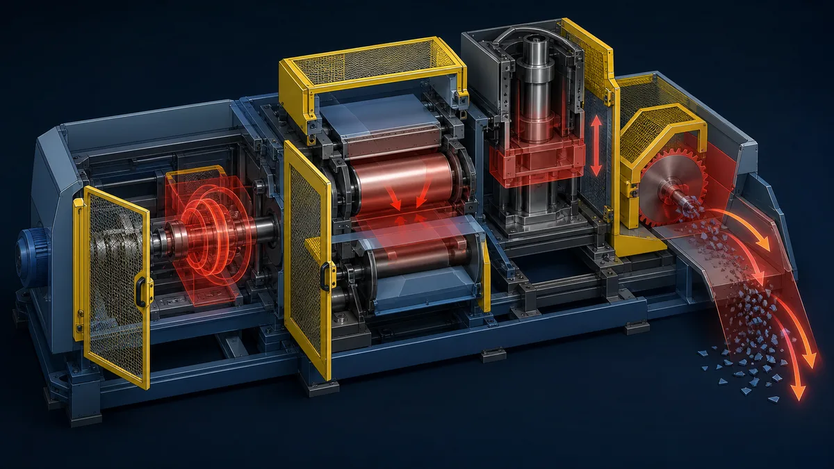
Machine guarding encompasses any method used to protect workers from the mechanical hazards a machine presents. Those hazards divide broadly into two categories: point of operation hazards (where the machine acts on the workpiece — the blade, the die, the chuck) and power transmission hazards (the shafts, belts, gears, and linkages that deliver energy to the point of operation).
The fundamental principle is separation — keep body parts out of the danger zone while the machine is capable of causing harm. How that separation is achieved depends on the hazard, the task, and the applicable standard. The word "guarding" is therefore an umbrella term that covers both guards (physical barriers) and safeguarding devices (equipment that detects or controls access without necessarily forming a physical barrier).
The Hazards Machine Guarding Protects Against
Understanding the hazard type drives the guard selection. OSHA and ISO standards both classify mechanical hazards into recognizable categories.
| Hazard type | Typical source | Example injury |
|---|---|---|
| Rotating motion | Spindles, chucks, pulleys, shafts | Entanglement, degloving |
| In-running nip points | Belt-and-pulley, gear mesh, roll pairs | Crush, amputation |
| Reciprocating motion | Press rams, injection moulding platens | Crush, fracture |
| Cutting / shearing | Band saws, shears, milling cutters | Laceration, amputation |
| Ejected material | Grinding sparks, swarf, broken tooling | Eye injury, penetrating trauma |
| Stored energy release | Spring-loaded mechanisms, pressure systems | Crush, impact |
A single machine can present several hazard types simultaneously. A horizontal band saw has a cutting hazard at the blade, rotating nip points where the blade runs over its wheels, and an ejection hazard from a snapped blade. The guarding solution must address all of them.
Types of Machine Guards
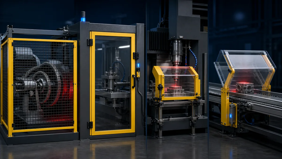
ISO 14120 — the international standard for guards — defines guard types by how they provide protection and how they interact with the machine's control system. OSHA 29 CFR 1910.212 uses broadly equivalent categories.
Fixed Guards
A fixed guard is a physical enclosure attached to the machine in a way that can only be removed using tools. No interlocks, no sensors — it simply blocks access to the hazard. Fixed guards are the most reliable form of protection because they cannot be inadvertently defeated and they do not depend on any control system to function.
Fixed guards are appropriate when:
- The guarded area does not require routine access for operation or adjustment.
- The guard can be sized and positioned to fully enclose the hazard zone.
- Maintenance access can be planned and performed under lockout/tagout.
Common examples include belt-and-pulley enclosures on the back of a conveyor drive, gear covers on a gearbox, and flywheel guards on a press.
Key requirement: A fixed guard must not be removable without tools, and it must be robust enough to contain ejected materials or withstand foreseeable forces. ISO 14120 specifies minimum distances from the guard opening to the hazard based on body-part reach distances (ISO 13857 safety distances).
Interlocked Guards
An interlocked guard is a movable panel, door, or enclosure fitted with a guard interlocking device — a switch, tongue switch, coded magnetic switch, or locking solenoid — that interacts with the machine's control system. When the guard is opened, the interlocking device sends a signal that prevents or stops hazardous machine motion.
Interlocked guards are used wherever routine access is required: feeding raw material, clearing jams, making adjustments, or performing short-interval maintenance.
There are three subfamilies worth distinguishing:
Interlocking without guard locking: Opening the guard sends a stop signal. The machine can be re-started only after the guard is closed again. This is suitable when the machine stops fast enough (coast-down time is short) that the operator cannot reach the hazard before motion ceases.
Interlocking with guard locking (trapped key or solenoid lock): The guard cannot be opened until the machine has reached a safe state (motion ceased, stored energy dissipated). Used when coast-down time is long enough that a worker could enter a still-moving danger zone. The lock is released either by a time-delay circuit, a zero-speed monitor, or manually via a trapped-key system.
Interlocking with guard locking and control: The safety system monitors both the guard position and the lock status. Opening is only possible after an explicit request signal, and the lock confirmation is part of the safety function feedback loop.
The interlocking switch itself must be selected with the required Performance Level (PL) or SIL in mind. Tongue switches and RFID-coded switches with dual-channel OSSD outputs are common choices for PLd/SIL 2 applications. See functional safety basics for an explanation of how PL and SIL are assigned.
Adjustable Guards
An adjustable guard is a fixed-structure guard with one or more components that can be repositioned — without tools — to accommodate different workpiece sizes or setups. The guard itself remains in place; only part of it moves to allow the workpiece to pass through.
A bandsaw blade guard that slides up to accommodate the thickness of a cut and returns to cover the blade as close to the workpiece as practical is a classic adjustable guard. A drill press chuck guard on a sliding arm is another.
The limitation of adjustable guards is that adjustment depends on the operator. If the guard is not correctly repositioned for each setup, protection may be incomplete. Adjustable guards are generally considered a lower-order solution than fixed or interlocked guards for this reason, and they are most appropriate when fixed or interlocked designs are not practicable.
Self-Adjusting Guards
A self-adjusting guard moves automatically in response to the workpiece, returning to its rest (closed) position as soon as the workpiece clears. Table saw blade guards that pivot upward as the workpiece advances over the table — and drop back down as the cut completes — are the canonical example.
Self-adjusting guards require no operator action and provide protection proportional to workpiece position. Their limitation is that they rely on the workpiece itself to provide protection during the cut, leaving the blade partially exposed during the cutting stroke. They are common on woodworking machinery where a fully enclosing guard would block the workpiece entirely.
Safeguarding Devices
Safeguarding devices do not form a physical barrier. Instead they detect the presence of a person (or body part) in a danger zone, or they require a deliberate two-handed action to initiate a machine cycle. Used alone or in combination with guards, they extend protection to situations where a physical barrier would be impractical.
Light Curtains (AOPD)
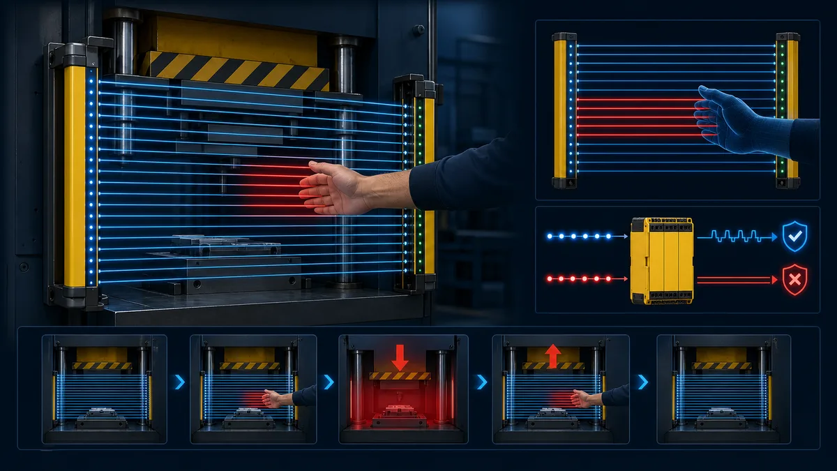
An active opto-electronic protective device (AOPD) — commonly called a light curtain — projects an array of parallel infrared beams across the access opening to a hazard zone. If any beam is broken, the device sends a stop signal to the machine's safety system.
Light curtains are well suited to high-cycle press and stamping applications where a guard door would slow production unacceptably. The machine can run continuously; the operator feeds parts through the light curtain field and withdraws before the downstroke.
Key parameters for specifying a light curtain:
- Resolution (minimum object detection): 14 mm detects fingers; 30 mm detects hands; 40–70 mm detects arms. Match to the closest body part that could be in the field.
- Safety distance: The curtain must be positioned far enough from the hazard that the machine stops before a hand can reach the danger zone after the beam is broken. ISO 13855 provides the calculation method.
- OSSD outputs: Safety light curtains have two redundant semiconductor output signal switching device (OSSD) outputs. Both must drop to 0 V on beam interruption. The safety relay or safety PLC monitors both channels; any discrepancy flags a fault.
Safety Laser Scanners (ESPE)
A safety laser scanner emits a rotating laser pulse and builds a 2D map of objects in a configurable protective field. It can detect a person anywhere in an area — not just along a line — making it suitable for robot cell perimeter guarding and AGV (automated guided vehicle) pedestrian detection.
Scanners offer configurable field shapes and multiple zones (warning zone plus stop zone) and can switch between field sets under program control. They are certified to PLd/SIL 2 or PLe/SIL 3 depending on the model and mounting. Safety distance calculation follows ISO 13855 for area scanners.
Two-Hand Control Devices
A two-hand control device requires the operator to press and hold two actuators simultaneously (typically within 0.5 s of each other) to initiate a hazardous machine cycle. Both hands are occupied on the controls and therefore outside the danger zone during the cycle.
Two-hand controls are a point-of-operation safeguarding method for single-operator presses and stamping machines. They are not a substitute for guarding when multiple operators are present, because they only account for the person operating the controls. ISO 13851 specifies the design requirements: anti-repeat, anti-tie-down, and synchronous actuation checks must be implemented.
Safety Mats and Pressure-Sensitive Edges
A safety mat is a pressure-sensitive floor mat placed in the approach to a hazard zone. Standing on the mat generates a signal that stops the machine or prevents a cycle from initiating. Safety mats are used for robot cell access, large press approaches, and anywhere a light curtain cannot be mounted conveniently.
A pressure-sensitive edge or bumper is a similar device fitted to moving machinery (robot arms, powered doors, AGV front edges) that stops motion on contact. Both devices use dual-channel resistive or capacitive sensing elements and connect to a safety relay or safety PLC via monitored inputs.
The Hierarchy of Controls Applied to Machine Hazards
Before selecting a guard type, ISO 12100 (General Principles for Design — Risk Assessment and Risk Reduction) requires applying risk reduction measures in priority order:
- Inherently safe design — eliminate the hazard. Reduce speed, use lower-force tooling, redesign the task so human access is not required.
- Safeguarding and protective measures — fixed guards, interlocked guards, presence-sensing devices. These are the measures covered in this article.
- Information for use — warnings, instructions, training, PPE. Information-for-use measures are the last resort, not the first response.
This hierarchy is a design discipline, but the exact documentation duty depends on the jurisdiction, machine and conformity route. ISO 12100 structures risk reduction in this order, while OSHA 29 CFR 1910.212 states the guarding outcome required for covered US workplaces. Record the risk assessment, selected measures and residual-risk instructions in the project safety documentation required for the machine.
OSHA 1910.212 and ISO 14120 Overview
OSHA 29 CFR 1910.212 — General Machine Guarding
OSHA's general machine guarding standard applies to all machinery not covered by a machine-specific standard. Its core requirements are:
- One or more methods of machine guarding must be used to protect operators and other employees in the machine area from hazards such as those created by point of operation, ingoing nip points, rotating parts, flying chips, and sparks.
- Guards must be affixed to the machine where possible; where not, they must be secured to prevent displacement.
- Guards must not create a hazard in themselves (sharp edges, pinch points).
- Point-of-operation guarding must prevent the operator from having any part of the body in the danger zone during the operating cycle.
OSHA also has machine-specific standards for woodworking machinery (1910.213), abrasive wheel machinery (1910.215), mechanical power presses (1910.217), and forging machinery (1910.218), each of which imposes additional requirements beyond 1910.212.
ISO 14120 — Guards: General Requirements
ISO 14120:2015 is the international standard that defines design and construction requirements for guards. Key provisions include:
- Guards must withstand the forces and impacts they will encounter in service, including ejected materials and foreseeable misuse.
- Openings in guards must meet the safety distance requirements of ISO 13857 — the larger the opening, the farther the guard must be from the hazard, because larger openings allow further reach.
- Interlocking devices used with movable guards must comply with ISO 14119.
- Guard design must consider cleaning and maintenance access to reduce the temptation to remove or defeat guards during routine tasks.
ISO 14120 works in conjunction with ISO 12100 (risk assessment), ISO 13857 (safety distances), ISO 14119 (interlocking devices), and ISO 13855 (positioning safeguards with respect to approach speeds). ISO 14119 was revised in 2024; use the edition adopted for the project and record any regional or customer-specific requirements.
How Guards Integrate with the Control System
This is where machine guarding moves from mechanical engineering into controls engineering — and where errors in implementation cause real accidents.
Interlock Switch to Safety Relay or Safety PLC
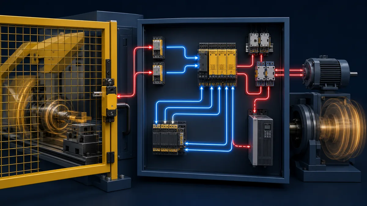
An interlocked guard switch is a safety-rated input device. Connecting it to a standard digital input on a conventional PLC is not adequate for any guard that is part of a safety function, because a standard PLC does not provide the diagnostic coverage, response time guarantees, or redundancy required by ISO 13849 or IEC 62061.
The correct architecture is:
- The guard switch has dual-channel outputs (NC/NC or OSSD pairs).
- Both channels wire to a dedicated safety relay or to safety-rated inputs on a safety PLC.
- The safety relay or safety PLC monitors both channels for agreement. A single-channel failure (one channel stuck high or low) is detected within the diagnostic test interval and triggers a safe state.
- The safety relay or safety PLC initiates the correct stop category — typically Category 0 (immediate de-energisation of the drive) or Category 1 (controlled stop followed by de-energisation) per IEC 60204-1.
For a detailed walkthrough of how stop categories and safety relays interact in a real circuit, see E-stop safety circuit in PLC ladder logic.
OSSD Signals from Presence-Sensing Devices
Light curtains and safety scanners output OSSD (Output Signal Switching Device) signals — two redundant PNP transistor outputs (OSSD1 and OSSD2) that are both active high (24 V DC) when the field is clear and both switch to 0 V when a beam is broken or an object is detected.
The safety relay or safety PLC monitors both OSSD outputs continuously. The outputs also pulse low briefly (test pulses, typically < 1 ms) to detect short circuits between OSSD1 and OSSD2. If the monitoring device sees one output low while the other is high for longer than the allowed discrepancy time, it flags a fault and demands a manual reset.
Wiring rules for OSSD signals:
- Route and protect both channels exactly as the device and safety-controller manuals require. Cable construction, segregation, test-pulse compatibility and permitted fault exclusions vary by product and architecture.
- Never connect OSSD outputs to standard PLC inputs without an intervening certified safety monitoring relay or safety PLC.
- Check the response time of the monitoring device against the stopping time of the machine when calculating the minimum safety distance.
Stop Categories and Guard Interactions
IEC 60204-1 defines three stop categories relevant to guard interlock design:
| Stop category | Action | Typical use with guards |
|---|---|---|
| Category 0 | Immediate removal of power to actuators | Fast-stopping machines; hazard from uncontrolled coast-down is low |
| Category 1 | Controlled stop (drives bring motion to rest), then remove power | High-inertia machines where uncontrolled coast-down is itself a hazard |
| Category 2 | Controlled stop, power remains available | Possible only where the risk assessment and safety-function design justify maintained power |
Many guard-interlock safety functions use Category 0 or Category 1. The category is not chosen by habit: it follows the risk assessment, stopping behavior, drive safety functions, and the hazards created by removing or maintaining power. A controlled Category 1 stop may be appropriate where uncontrolled coast-down creates another hazard; any Category 2 safety use needs a validated architecture that keeps the stop condition under safety-related control.
When guard locking is required, the lock must not release until the machine has achieved its stop condition. This is typically implemented using a standstill monitor (a certified speed detection relay or safety PLC function block) that confirms zero speed before issuing the unlock command.
For a deeper look at how these architectures relate to the broader safety system, the safety PLC vs standard PLC comparison guide covers when a dedicated safety controller is required and what certified architecture it must implement.
Selecting the Right Safeguard
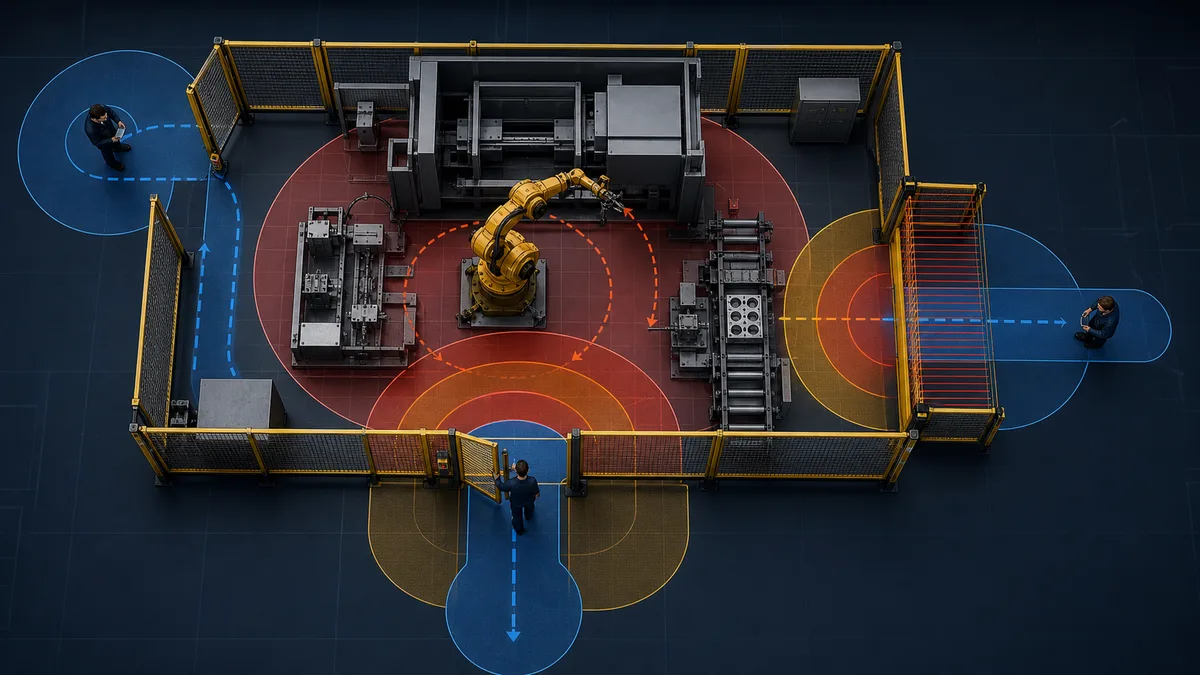
No single guard type suits every application. ISO 12100 Annex B provides a framework for selection; in practice, the decision reduces to four questions:
1. How often is access required? Frequent access (each cycle, each hour) makes a fixed guard impractical and points toward an interlocked guard, a light curtain, or a two-hand control. Infrequent access (quarterly maintenance only) favours a fixed guard with lockout/tagout for the maintenance event.
2. How long does the machine take to stop? If the machine stops before a person can reach the hazard after the guard is opened or a presence-sensing device is interrupted, an interlock without guard locking or a correctly positioned protective device may be suitable. If hazardous motion persists, guard locking or another validated access-prevention design may be necessary. A two-hand control only protects its intended operator and does not solve unrestricted access by other people.
3. What is the severity of injury if the safeguard fails? High-severity hazards demand higher-reliability safeguards, but severity alone does not assign a Performance Level or SIL. Determine the required risk reduction with the applicable risk-estimation method, then validate the complete safety function: sensor, logic, output devices, diagnostics, wiring, response time, and fault exclusions.
4. Are there secondary hazards from the safeguard itself? A light curtain that mutes automatically during the ejection portion of a press cycle may leave the operator unprotected at a critical moment. A guard door that opens inward into a narrow aisle creates a struck-by hazard. Every safeguarding solution must be evaluated for the hazards it introduces, not just the hazards it mitigates.
Downloadable machine-guarding risk review
Foreseeable misuse belongs in the review. Inspect whether a switch can be misaligned or defeated, whether a person can remain inside a large zone unseen from reset, whether a welded final contact is detected, and whether production pressure encourages removal of a panel. The response is better task design, appropriate anti-defeat measures, diagnostics and validation—not publishing or normalizing a bypass method.
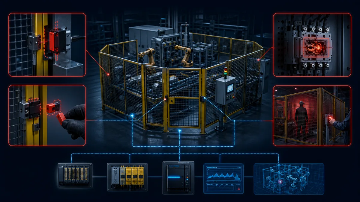
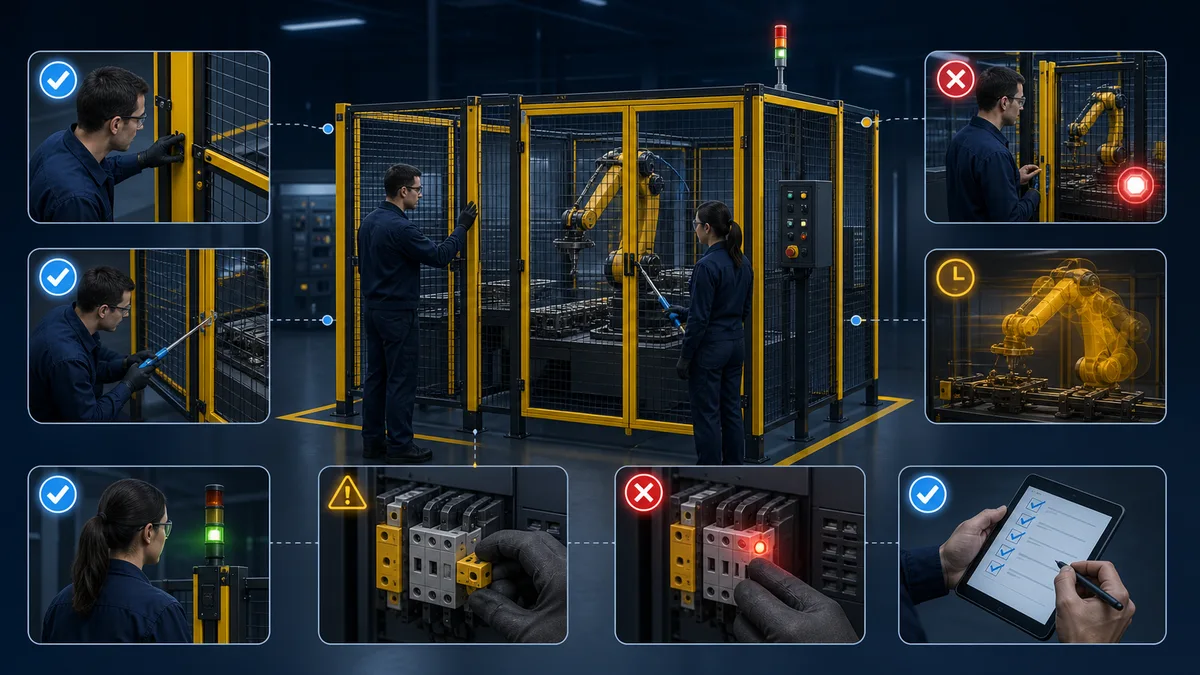
A safeguard review should cover every human interaction, not only automatic production. Include loading, setup, jam clearing, cleaning, teaching, maintenance, and foreseeable bypass attempts. For each task, capture the hazardous energy, exposed person, access frequency, stopping time, required risk reduction, selected device, reset/restart behavior, and validation evidence.
Download the machine-guarding risk-review worksheet (CSV). It is a planning aid, not a risk-assessment method or certification. Pair it with the applicable standards, the machine manufacturer's instructions, and a competent safety engineer. Use the safety-relay validation checklist for discrete relay-based functions and the lockout/tagout procedure guide for maintenance energy isolation.
Guard-type selection matrix
| Safeguard | Strong fit | Important limitation | Evidence to retain |
|---|---|---|---|
| Fixed guard | Infrequent access; transmission hazards; containment | Removal can expose the hazard; openings and fasteners still matter | Drawings, material/impact basis, opening and reach checks, fastener inspection |
| Interlocked movable guard | Routine loading, setup or inspection access | Stop time may require guard locking; defeat and misalignment are foreseeable | Switch/actuator data, safety-function calculation, stop-time results, fault tests |
| Light curtain or scanner | Frequent unobstructed access where detection can initiate a timely stop | Does not contain ejecta, heat or emissions; can be reached around if badly positioned | Device configuration, separation-distance basis, response time, full-field tests |
| Two-hand control | A defined single-operator cycle where both hands must be kept away | Does not protect another person and is not perimeter protection | Control location, simultaneity/anti-repeat tests, stopping performance |
| Safety mat or edge | Presence or contact detection where optical sensing is unsuitable | Wear, dead zones and bypass routes require evaluation | Layout, sensitivity tests, environmental limits, periodic inspection plan |
Safety-chain review matrix
| Chain element | Review question | Example evidence | Do not infer |
|---|---|---|---|
| Sensor or interlock | Does it detect every specified access state and relevant fault? | Certified manual, wiring drawing, alignment/actuation test | A device type alone establishes the complete PL or SIL |
| Safety logic | Are channel discrepancy, reset, muting and timing handled as specified? | Validated function block, parameter record, test results | A standard PLC diagnostic tag is the safety decision |
| Final element | Does the machine reach the defined safe state, including a welded-device case? | Contactor/drive data, EDM feedback test, measured stop | A commanded output means hazardous motion has ended |
| Mechanics | Can a person reach the hazard before it is safe, or bypass another route? | Reach/opening measurements, stopping-time distribution, cell survey | The electrical response time is the total stopping time |
| Human interaction | Can reset occur with a person unseen inside, or can normal work incentivize defeat? | Reset sightline review, task observation, trapped-person and restart tests | Training compensates for an avoidable design incentive |
Commissioning and periodic-test matrix
| Test case | Expected safe behavior | Record |
|---|---|---|
| Open each movable guard during every relevant operating mode | Hazardous motion follows the specified stop response; restart remains inhibited | Mode, speed/load, stop response, channel state, result |
| Fault one input channel at a time using an approved test method | The diagnostic detects the fault within the specified interval and blocks unsafe restart | Injected fault, diagnostic code, output state, reset behavior |
| Simulate a final-element feedback fault | Reset/re-enable is prevented according to the safety requirement | EDM state, observed contactor/drive state, recovery steps |
| Measure stopping performance across representative load and temperature | Worst credible result remains inside the validated access/separation basis | Instrument, conditions, individual readings, selected worst case |
| Attempt restart from each reset/start station after access | No unexpected hazardous restart; operator has the visibility required by the design | Station, visibility, retained command state, result |
| Inspect fixed guards, openings and fasteners | No reach path, damage, displacement or missing retention undermines protection | Location, dimensions, condition, corrective action |
Requirement-to-source map
| Design question | Start with | Project-specific follow-up |
|---|---|---|
| What mechanical hazards and tasks exist? | ISO 12100 risk-assessment and risk-reduction process | Machine limits, task observation, lifecycle and foreseeable misuse |
| How should a physical guard be constructed? | ISO 14120 plus any machine-specific standard | Material, strength, impact, openings, cleaning and access |
| How should an interlocking device be selected? | ISO 14119:2024 | Device manual, coding/actuation, defeat incentive, locking need |
| How far must a barrier or protective device be from the hazard? | ISO 13857 for reaching; ISO 13855:2024 for safeguard positioning | Actual geometry, approach, response time and measured stopping time |
| What integrity must the control function achieve? | ISO 13849-1 or IEC 62061, as applicable | Safety requirement specification, subsystem data, calculation and validation |
| What does US workplace law require? | OSHA 29 CFR 1910.212 and applicable machine-specific rules | Site jurisdiction, machine class, company policy and competent review |
Frequently Asked Questions
What is machine guarding?
Machine guarding is the use of physical barriers (guards) and safety devices to prevent workers from contacting the hazardous parts of a machine — rotating elements, cutting edges, pinch points, and ejected materials — during normal operation, setup, and maintenance.
What are the types of machine guards?
The four main types are: fixed guards (permanently attached, require tools to remove), interlocked guards (movable barriers linked to the machine's control system via a safety switch), adjustable guards (repositioned manually for different workpiece sizes), and self-adjusting guards (move automatically with the workpiece). Safeguarding devices — light curtains, safety scanners, two-hand controls, and safety mats — are sometimes grouped with guards but are technically a separate category.
What is the difference between a guard and a safeguarding device?
A guard is a physical barrier that prevents access to a hazard zone. A safeguarding device detects a person entering the hazard zone (or requires a deliberate two-handed action) and sends a stop signal to the machine — it does not physically block entry. Guards protect passively; safeguarding devices protect actively via the machine's control system.
What does OSHA require for machine guarding?
OSHA 29 CFR 1910.212 requires that one or more methods of machine guarding be used wherever machines present a hazard from rotating parts, ingoing nip points, flying chips or sparks, or point-of-operation hazards. Guards must be affixed to the machine or secured against displacement, must not create additional hazards, and must prevent the operator from reaching into the danger zone during the operating cycle. Machine-specific standards (1910.213–1910.218) add further requirements for woodworking, abrasive wheels, mechanical power presses, and forging machinery.
When should a machine guard be interlocked?
Use an interlocked movable guard when the protected area needs routine access and opening it must initiate or prevent hazardous motion. Whether guard locking is also required depends on how quickly the hazard ends compared with how quickly a person can reach it. The complete safety function and restart behavior require a risk-based design and validation.
Is a light curtain a machine guard?
A light curtain is normally classified as a safeguarding or presence-sensing device, not a physical guard. It can detect entry and demand a stop but cannot contain a broken tool, hot material or ejected workpiece. The risk assessment must decide whether detection alone is sufficient or a physical barrier is required.
How do I choose between a fixed guard and an interlocked guard?
A fixed guard is usually preferred where access is infrequent because protection does not depend on a control system. An interlocked guard is useful where loading, setup or cleaning requires routine access. Consider access frequency, removal incentives, hazard stopping time, containment, locking and validation rather than convenience alone.
Can an interlocked guard connect to a standard PLC input?
The state may be mirrored to a standard PLC for diagnostics, but a standard input and program are not automatically suitable for the claimed safety function. Use a safety-related architecture designed and validated for the required PL or SIL, following the exact device and controller manuals.
Does opening a guard always remove electrical power?
No. The specified response may be an uncontrolled stop, a controlled stop followed by torque inhibition, or another validated safety function. Electrical energy and other stored energy can remain. Covered servicing requires the applicable energy-isolation and lockout/tagout procedure.
How should machine guarding be validated?
Validate physical strength and attachment, openings and reach, every access task, stopping time, each interlock and channel, final-element feedback, reset/restart behavior, guard locking, foreseeable faults and changes. Record expected and observed results against the safety requirement specification.
Primary sources and limitations
This guide explains concepts and review surfaces; it is not a machine-specific risk assessment, legal opinion, safety-function calculation or commissioning procedure. Editions adopted into law or customer specifications can differ by country. Use the complete purchased standards, the installed product manuals and a competent machinery-safety professional before changing a real machine.
- OSHA 29 CFR 1910.212 — General requirements for all machines
- OSHA Machine Guarding eTool — Introduction
- OSHA 29 CFR 1910.147 — Control of hazardous energy
- ISO 12100:2010 — Risk assessment and risk reduction
- ISO 14120:2015 — Fixed and movable guards
- ISO 14119:2024 — Interlocking devices associated with guards
- ISO 13857:2019 — Safety distances for upper and lower limbs
- ISO 13855:2024 — Positioning safeguards
- ISO 13849-1:2023 — Safety-related parts of control systems
- IEC 60204-1:2016+A1:2021 — Electrical equipment of machines
- IEC 62061:2021 — Functional safety of machinery control systems