Functional Safety Basics: A PLC Engineer's Practical Guide (2026)
Functional safety explained for controls engineers — the safe state, the safety lifecycle, IEC 61508/61511/62061 standards, SIL, and what changes in your PLC and panel.
Functional safety is the part of overall safety that depends on the correct functioning of electrical, electronic, or programmable electronic (E/E/PE) systems — meaning the machine or process must reach a defined safe state whenever those systems fail or detect a hazardous condition.
What Is Functional Safety?
Every industrial machine can hurt someone if it does the wrong thing at the wrong moment. Functional safety is the engineering discipline that quantifies that risk, decides how much of it needs to be controlled by an automated system, and then proves that the system is reliable enough to do the job.
The phrase matters because it draws a clear boundary: functional safety covers only the safety delivered by a function. A physical guard rail protects workers whether the control system is on or off — that is not functional safety. An emergency shutdown that fires a solenoid valve when pressure exceeds a set point is functional safety, because it only works if the sensor, the logic solver, and the final element all do their jobs correctly.
If you are new to the discipline, think of it as a structured answer to the question: "If this control system fails, does someone get hurt?" The standards give you a method to answer that question rigorously and document the answer in a way regulators and insurers will accept.
The Safe State — The Foundation of Every Safety Function
Before you write a single line of safety logic, you must define the safe state for every hazard the function addresses. The safe state is the condition a machine or process must reach to eliminate or adequately reduce the hazard.
Safe states are almost always energize-to-trip systems. Examples:
- High pressure in a vessel — safe state is feed valve closed and vent valve open.
- Robot work cell during access — safe state is all axes at rest and power removed from drives.
- Conveyor with a pinch point — safe state is belt stopped.
The safe state determines everything downstream: which final elements must activate, which direction of de-energization is "safe," and what the wiring philosophy must be. A solenoid valve that fails to open on loss of power cannot be the final element of an emergency depressure function — it would need to be fail-open. This is why fail-safe design is inseparable from safe state definition.
How E/E/PE Systems Reduce Risk
Functional safety standards deal specifically with risk reduction achieved by electrical, electronic, and programmable electronic systems. The classic risk reduction model looks like this:
- Identify the hazardous event and its associated risk (severity × likelihood without protection).
- Determine the tolerable risk — what level of residual risk is acceptable.
- Calculate the risk reduction required — the gap between unmitigated risk and tolerable risk.
- Allocate risk reduction across layers: inherently safe design, passive protection, active protection (E/E/PE), and procedural controls.
- Specify the safety function — the automated action that delivers the required risk reduction.
The portion of the required risk reduction that is assigned to an E/E/PE safety function becomes the Safety Integrity Level (SIL) target for that function. Higher SIL means the function must be more reliable. See the full explanation on the SIL guide.
The Safety Lifecycle
The safety lifecycle is the structured process that takes a hazardous situation from initial concept through operation and decommissioning. IEC 61508 defines 16 phases; the practical structure that most engineers work with breaks down into four stages.
1. Concept and Hazard Analysis
Define the equipment under control (EUC), identify hazardous events, and determine the risk each event represents. Tools at this stage include HAZOP, FMEA, and Layer of Protection Analysis (LOPA). The output is a list of safety functions and their SIL targets.
2. System Design and Specification
Write the Safety Requirements Specification (SRS) for each safety function. The SRS captures the safe state, the trigger condition, the response time requirement, the architecture, and the SIL target. This is the contract document for the rest of the lifecycle.
3. Realisation
Procure hardware (certified safety PLC, safety-rated sensors, certified final elements), write and verify the safety application program, and integrate the safety system into the machine or process. Functional testing and SIL verification calculations happen here.
4. Operation, Maintenance, and Proof Testing
A safety function that is never tested will degrade silently. Proof testing at defined intervals forces every part of the safety function to operate as intended — including the parts that normally sit dormant waiting for a demand. The required proof test interval is a design input, not an afterthought.
Understanding the lifecycle matters because a correctly designed safety function is only as good as the process that produced it. Shortcuts at the hazard analysis stage produce under-specified safety functions; shortcuts at the proof testing stage cause real-world failures.
Key Standards at a Glance
Functional safety is governed by a family of standards. IEC 61508 is the umbrella standard — the foundational framework that the sector-specific standards derive from.
| Standard | Sector | Focus |
|---|---|---|
| IEC 61508 | All industries | E/E/PE safety-related systems; defines SIL 1–4 |
| IEC 61511 | Process industry | Safety instrumented systems (SIS) for oil, gas, chemicals |
| IEC 62061 | Machinery | Safety-related control systems; uses SIL 1–3 |
| ISO 13849 | Machinery | Safety-related control systems; uses Performance Level (PLa–PLe) |
| ISO 26262 | Automotive | Road vehicles; uses Automotive SIL (ASIL A–D) |
IEC 61511 is the standard most process engineers encounter directly. It governs Safety Instrumented Systems (SIS) — the combination of sensor, logic solver, and final element that implements a safety instrumented function (SIF). If you work in oil and gas, chemical processing, or water treatment, IEC 61511 is your primary reference.
IEC 62061 and ISO 13849 cover machinery and are the standards you meet when designing safeguarding for robot cells, presses, and conveyor systems. ISO 13849 uses the Performance Level (PL) metric, which maps to SIL ranges and is familiar to many machinery engineers.
The sector-specific standards do not contradict IEC 61508 — they apply it to a specific domain and often add practical requirements that the general standard leaves to the user's judgment.
Functional Safety on a Real Machine — What the PLC Engineer Actually Does
Reading the standards is one thing. Here is what changes on your bench and in your panel.
Safety PLC vs Standard PLC
A standard PLC has no hardware mechanisms to detect its own internal failures. A safety PLC adds:
- Dual-processor architecture with cross-comparison (both CPUs must agree on every output state before the output is driven).
- Watchdog functions that force outputs to the safe state if the CPU stops responding within a defined time window.
- Diagnostic coverage of memory, I/O modules, and communications — these are the fault detection mechanisms that contribute to the SIL calculation.
- Certification against IEC 61508 or IEC 62061, giving you a documented probability of dangerous failure per hour (PFH) for the logic solver.
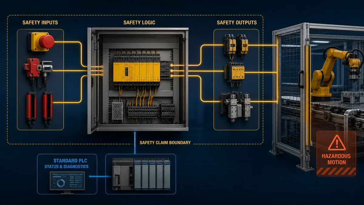
The safety PLC does not replace your standard PLC. In most architectures, the safety PLC handles only safety functions; the standard PLC handles all production logic. They communicate, but the safety PLC never allows the standard PLC to override a safe state. See the full comparison at Safety PLC vs Standard PLC.
Dual-Channel I/O
Safety functions almost always require redundant sensing. A dual-channel input uses two independent sensors — often of different technology (e.g., one pressure transmitter and one pressure switch) — wired to separate input cards. The safety logic monitors both channels, and discrepancies between them trigger a fault state. This architecture detects stuck-at faults that a single channel would miss entirely.
On the output side, safety-rated final elements often use redundant output channels with cross-monitoring — two contactors in series, for example, with position feedback monitored independently.
Safety-Rated Logic Blocks
Most safety PLC platforms provide certified function blocks — pre-validated logic elements for common safety patterns such as two-hand control, light curtain monitoring, emergency stop monitoring, and muting. Using certified blocks reduces the validation burden on your application program because the block itself already carries a SIL or PL certification.
You do not write raw ladder logic to implement a safety function and then argue that it is correct. You use the certified block, configure it, and document the configuration.
Safety Functions as You Would Write Them
A safety instrumented function (SIF) has three components: trigger, action, and response time requirement.
Example — high pressure emergency shutdown:
- Trigger: Pressure transmitter PT-101 ≥ 85 bar (dual-channel, both channels must agree; single channel failure triggers a fault alarm, not a spurious trip).
- Action: De-energize solenoid valve XV-101 (fail-closed feed valve) and energize solenoid valve XV-102 (fail-open vent valve).
- Response time: Valve XV-101 must reach the closed position within 3 seconds of the trigger condition being confirmed.
- Safe state: XV-101 closed, XV-102 open, pressure confirmed falling.
This framing — trigger, action, response time — maps directly to the Safety Requirements Specification and to the test procedure you write for proof testing. Every field that matters for the safety case is explicit.
Note that the response time requirement must be verified at commissioning and at every proof test. If your valve takes 4.5 seconds to close, the safety function does not meet its specification regardless of how good the logic is.
Where This Bites in Practice
Proof Testing Is Not Optional
The SIL calculation for a safety function assumes that proof tests happen at the interval specified during design. Miss the test interval and the actual PFD (probability of failure on demand) drifts above the SIL threshold — you have a safety function that is no longer compliant, and you may not know it. Build proof test procedures into your maintenance management system and treat them with the same rigor as a statutory inspection.
Diagnostics Must Cover the Entire Loop
A common mistake is certifying the logic solver and then connecting it to uncertified sensors and valves. The SIL of the complete safety function is limited by the weakest element in the loop. Diagnostic coverage of the field devices — not just the PLC — must be part of the design.
An E-Stop Cannot Be a Normal Rung
A standard E-stop wired to a normally-open auxiliary contact feeding a standard PLC input is not a safety function. It has no diagnostic coverage, no cross-monitoring, and no certified PFH value. A true E-stop circuit uses safety-rated hardware, positive-opening contacts, and a certified safety relay or safety PLC input module. The E-stop safety circuit guide covers the wiring and logic in detail.
Documentation Is Part of the Product
The safety case — the collection of documents that demonstrates the safety function meets its SIL target — is a deliverable. It includes the SRS, the architecture justification, the SIL verification calculation, the FAT and SAT records, and the proof test procedures. Without it, you cannot demonstrate compliance and you cannot defend the design if an incident occurs.
For broader PLC programming discipline that underpins good safety application work, see PLC programming best practices and the industrial control systems guide.
Functional safety sits at the intersection of engineering rigor and legal obligation. The standards are demanding by design — a safety function that is easy to specify and never tested is not actually providing safety. The practitioner's advantage is understanding that the standards are a framework, not a bureaucratic obstacle: they exist to make sure you have thought about every failure mode before the machine does it for you.
For related reading, see functional safety vs process safety for a clear distinction between the two disciplines.
Frequently Asked Questions
What is functional safety?
Functional safety is the part of overall safety that depends on electrical, electronic, or programmable electronic systems functioning correctly. A system is functionally safe if it reaches a defined safe state whenever a hazardous condition is detected or whenever the system itself fails.
What is the safety lifecycle?
The safety lifecycle is the structured process — defined in IEC 61508 — that governs a safety system from initial concept through operation and decommissioning. Its key stages are hazard analysis, safety requirements specification, system design and realisation, and ongoing operation with proof testing. Every stage produces documented evidence that the safety function meets its integrity target.
What standards cover functional safety?
The umbrella standard is IEC 61508, which applies to all electrical, electronic, and programmable electronic safety-related systems. Sector-specific standards derived from it include IEC 61511 (process industry), IEC 62061 and ISO 13849 (machinery), and ISO 26262 (automotive). Most controls engineers working in process plants use IEC 61511; those working on machinery use IEC 62061 or ISO 13849.
What is the difference between functional safety and safety?
"Safety" is the broad goal — freedom from unacceptable risk. Functional safety is a specific subset: the portion of safety that depends on an automated system functioning correctly. Physical guards, inherently safe design choices, and administrative procedures contribute to overall safety but are not part of functional safety. Functional safety standards deal exclusively with E/E/PE systems.
What is a safety PLC?
A safety PLC is a programmable logic controller that has been designed and certified to execute safety functions up to a defined SIL or Performance Level. Unlike a standard PLC, a safety PLC incorporates dual-processor cross-comparison, watchdog circuits, diagnostic coverage of its own hardware, and a documented probability of dangerous failure per hour (PFH) — all verified by a third-party certification body against IEC 61508 or IEC 62061.