Safety PLC vs Standard PLC: Selection, SIL/PL and Programming
A standards-based safety PLC guide covering architecture, safety relay versus safety PLC selection, SIL and PL boundaries, programming, diagnostics, validation and change control.
Direct answer: what a safety PLC is and when to use one
A safety PLC is a programmable controller whose specified hardware, firmware, engineering workflow, instructions, communications and diagnostic measures are certified for safety-related use within defined conditions. A standard PLC is designed for ordinary automation. It may display safety status or control production, but it should not be credited as the safety logic merely because its program looks reliable.
Use a safety PLC when a documented risk assessment and safety requirements specification lead to safety functions whose complexity, interaction, distribution, diagnostics or lifecycle are better served by a programmable certified system than by a valid simpler architecture. Do not choose one from a shortcut such as “PL d always needs a safety PLC” or “SIL 2 means dual processors.” The required Performance Level (PLr) or Safety Integrity Level (SIL) belongs to a complete safety function. The controller is one subsystem in that function, and the selected architecture must be evaluated in its exact configuration.
For one or two stable local functions, a fixed safety relay can be the clearest and most maintainable answer. A configurable safety controller often fits a medium-complexity machine. A safety PLC becomes compelling when there are many functions or zones, safe communications, coordinated stopping, reusable safety software, rich diagnostics, or controlled integration with standard automation. Product certificates and safety manuals determine what is permitted; the label on the controller does not certify the installed machine.
| Question | Practical answer |
|---|---|
| Does a high required PLr or SIL automatically select a safety PLC? | No. It defines required performance for a safety function; architecture selection is a separate, evidence-based decision. |
| Can a standard PLC be the normal machine controller? | Yes. That is its intended role, including production sequencing, recipes, HMI data and ordinary diagnostics. |
| Can a standard PLC read safety status? | Often yes, through a documented status-only interface. It must not override the safe state or silently become part of the credited safety path. |
| Is a safety relay always safer than a safety PLC? | No. Either can be appropriate within its certified application. Complexity, maintainability and lifecycle controls matter. |
| Does simulation validate a safety application? | No. Simulation can support logic learning and test preparation, but it cannot validate real devices, wiring, timing, faults, final elements or achieved PL/SIL. |
This guide owns the safety-PLC architecture, selection, programming, diagnostics and validation task. Use the separate guides for a deeper treatment of SIL, Performance Level under ISO 13849, and SIL versus PL.
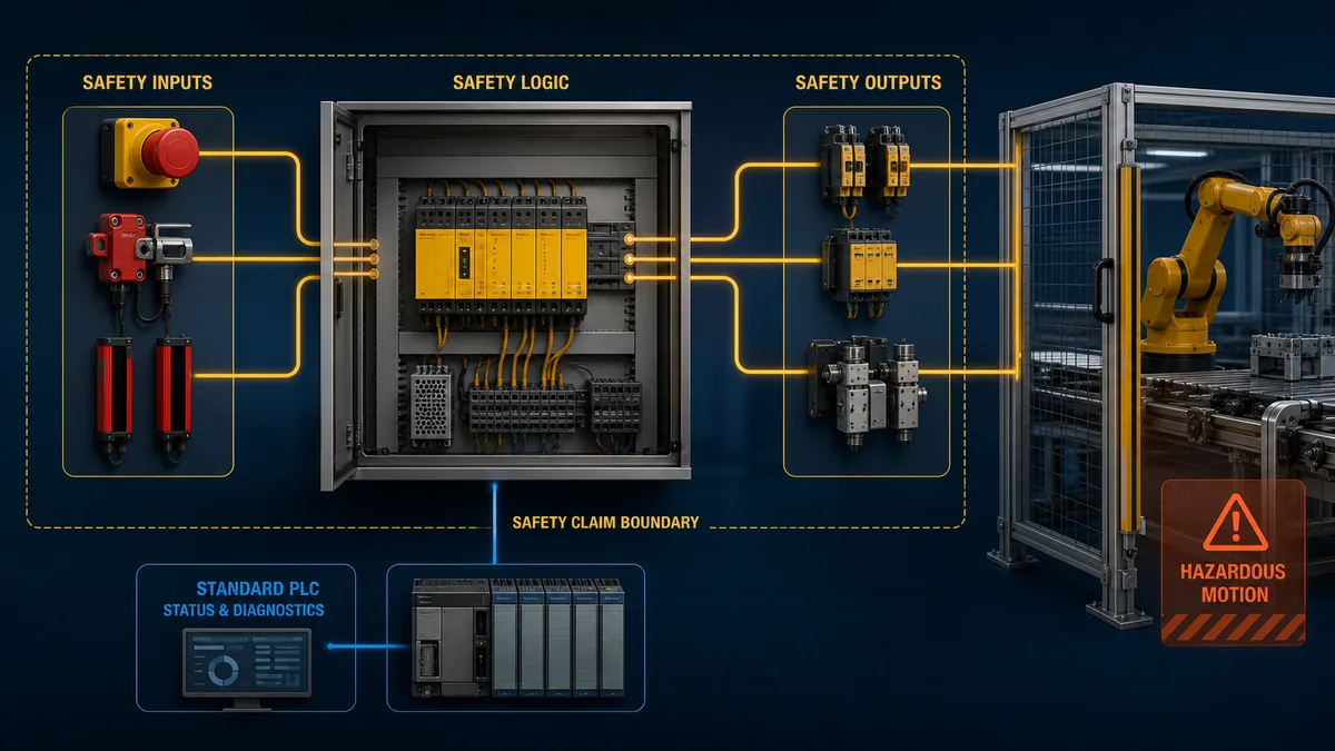
Start with the complete safety function, not the controller
The most common design error is to begin with a controller catalogue. Functional safety begins earlier. Define the machine limits and operating modes, identify hazards, reduce risk through inherently safe design and safeguarding where possible, and specify any safety-related control functions that remain necessary. Only then can the team decide what logic subsystem belongs in the solution.
A useful safety-function statement is testable. “Guard door safe” is too vague. A better statement names the initiating condition, required response, affected hazards, operating modes, response time, reset behavior, restart behavior, fault response and interfaces. For example: when either channel of a packaging-cell guard interlock is opened in automatic mode, torque-producing power to specified axes is removed through the defined final elements within the validated response limit; closing the guard does not restart motion; a deliberate reset outside the hazard zone restores readiness only after all monitored conditions are healthy.
That statement exposes the full chain:
- the guard device and its mechanical installation;
- the channel wiring and fault-detection assumptions;
- fail-safe input modules and their parameters;
- safety logic, task timing and approved instructions;
- safe communication where used;
- fail-safe outputs and final switching elements;
- drive, contactor, valve, brake or actuator behavior;
- mechanical stopping performance at the machine;
- reset, restart and mode-selection behavior;
- verification, validation, inspection and change records.
A controller certificate covers only what it says it covers. It may identify a maximum systematic capability, architectural constraints, safety integrity capability, hardware and firmware combinations, proof-test assumptions, programming tools and supported instructions. It cannot know how a particular sensor was mounted, whether an output was wired within its diagnostic assumptions, whether a brake stops the actual load, or whether software implements the requirements correctly.
| Safety-function element | Design evidence | Validation evidence |
|---|---|---|
| hazard and required response | risk assessment, Type-C standard, safety requirements | trace from each hazard to an implemented and tested function |
| input subsystem | device certificate, safety manual, wiring concept, reliability data | actuation, discrepancy, shorts/open circuits where applicable, environmental and mechanical checks |
| logic subsystem | exact controller/I/O certificate, firmware, safety manual, program specification | reviewed logic, task timing, controlled download, signature/version, functional and fault tests |
| output and final element | ratings, diagnostic assumptions, contactor/valve/drive data | feedback behavior, de-energization, fault response, stopping or pressure-decay measurement |
| reset and restart | mode/state specification and interface design | reset restores readiness only; no unexpected restart; visibility and reach are acceptable |
| lifecycle | configuration-management and maintenance plan | released baseline, test records, inspection intervals, modification impact assessments |
Standards boundary as of 30 August 2026
For machinery, ISO 12100:2010 remains the published general risk-assessment and risk-reduction standard, although ISO reports a revision in development. ISO 13849-1:2023 is the current fourth edition for designing and integrating safety-related parts of control systems in high-demand and continuous modes. Its own scope says it does not choose the safety functions or required PLr for a particular application.
IEC 62061:2021 is the machinery-sector functional-safety standard for safety-related control systems. IEC published Amendment 1 in 2024 and Amendment 2 in March 2026. The 2021 edition strengthened functional-safety planning, configuration management, parameterization, periodic testing, software use cases, verification independence and validation. Use the adopted edition and amendments applicable to the machine, contract and jurisdiction.
ISO 13849-2:2012 remains published for validation by analysis and testing, with a replacement draft under development. IEC 60204-1:2016 with Amendment 1:2021 addresses electrical equipment of machines, including control circuits and power-drive topics. Type-C machinery standards, local law, workplace rules and customer specifications may add or change requirements.
This standards status matters because older online material often treats ISO 13849-1:2015 or the first edition of IEC 62061 as current, calls every safety controller a “SIL 3 PLC,” or presents a universal mapping as a design decision. Use an internet guide to understand the workflow, then verify the actual normative text, adopted regional version, product certificates and current manuals.
| Decision layer | Governing question | Typical evidence source |
|---|---|---|
| risk reduction | What hazards exist and what risk remains after higher-order measures? | ISO 12100 method, task analysis, incident history, machine-specific standard |
| safety-function requirement | What must the control system do, how quickly and in which modes? | safety requirements specification, Type-C standard, risk evaluation |
| required performance | What PLr or SIL is required for each function? | applicable standard method and competent engineering judgment |
| architecture | Which sensor–logic–output design can meet the requirement? | certificates, safety manuals, calculation data, environmental and mission assumptions |
| implementation | Is the exact hardware, software and configuration within certified use? | product-specific manuals, approved instructions, version matrix, program review |
| validation | Does the installed machine satisfy each requirement under relevant conditions and faults? | analysis, controlled tests, measurements, signed results and deviations |
SIL and Performance Level do not select the controller by themselves
SIL and PL are related measures of the dependability of safety functions, but their methods and scopes are not interchangeable labels for products. A machine designer may use ISO 13849-1, IEC 62061, a machine-specific standard, or a permitted combination. The chosen route should be stated at the start of the project and applied consistently.
Under ISO 13849-1, the achieved PL depends on more than a controller’s headline certification. Architecture/category, dangerous-failure data, diagnostic coverage, common-cause measures, mission time and systematic/software measures all matter. Under IEC 62061, subsystem architecture, failure rates, diagnostics, systematic integrity and the complete safety-related control system matter. The sensor and final element frequently dominate the real function as much as the logic solver does.
The safe statement is: select a complete architecture capable of achieving the required performance under its documented assumptions. The unsafe shortcut is: PL d equals safety PLC. A fixed safety relay can participate in a high-performing function if the exact application and complete calculation support it. A programmable safety controller can fail to achieve the target if the configuration, I/O, wiring, final elements or lifecycle are wrong.
The same caution applies to standard PLCs. DGUV Test’s 2022 paper, “Can PL c be achieved with a standard PLC?”, explains why ordinary complex electronics cannot simply be treated as well-tried Category 1 components from field reliability anecdotes. Do not convert that discussion into the opposite blanket claim that a standard PLC is never present around a safety function. A standard PLC can handle production and status, while the credited safety path uses an appropriate relay, controller or other assessed architecture.
Keep requirement, capability and achievement separate
| Term | What it describes | What it does not prove |
|---|---|---|
| required PLr or SIL | the necessary risk-reduction performance of a specified function | the brand, controller family or topology to buy |
| product maximum/capability | the highest level supported within certified conditions | that every use of the product reaches that level |
| achieved PL or SIL | the evaluated performance of the implemented complete function | that unrelated functions on the same machine share the result |
| category or architecture | structural behavior under faults and diagnostic assumptions | complete performance without reliability and systematic measures |
| safety PLC | a programmable logic subsystem designed for certified safety use | a safe machine, correct safety program or validated stop |
Safety relay, configurable controller or safety PLC
The right architecture is the least complex option that meets the requirements and can be installed, validated, maintained and changed correctly over its life. “Least complex” does not mean cheapest hardware at purchase. It means the fewest uncontrolled interactions and the clearest evidence path for the real machine.
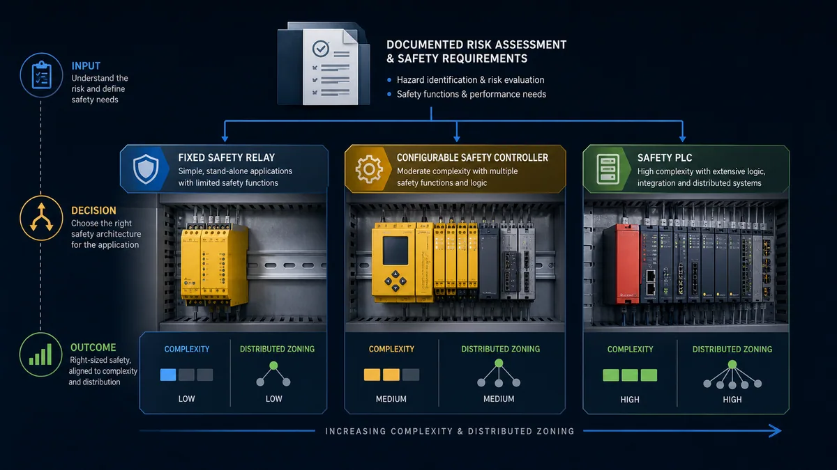
Fixed-function safety relay
A fixed relay is strong when the machine has a small number of independent, stable functions and the manufacturer manual contains a suitable application. It can be easy to inspect and replace, and its logic is often visible from wiring and settings. Its apparent simplicity is not permission to improvise: channel arrangement, sensor supply, start/reset mode, external device monitoring, output expansion, contact ratings and fault response are product specific.
Configurable safety controller
A configurable controller bridges relays and full safety PLCs. It can manage several functions, zones and diagnostic messages with approved graphical blocks. The lifecycle burden is higher than for a fixed relay because configuration files, tool versions, passwords, signatures, parameters and change records matter. Treat it as safety software, even when the vendor calls the experience “configuration.”
Safety PLC
A safety PLC is strongest when the application needs distributed fail-safe I/O, safe communications, coordinated zones, reusable verified blocks, safe motion integration, structured diagnostics, or many interacting safety functions. It may combine standard and safety tasks in one physical platform, but their authority and data paths remain controlled. An integrated platform can reduce hardware and wiring; it can also concentrate configuration risk if access, review and release discipline are weak.
| Selection factor | Fixed safety relay | Configurable controller | Safety PLC |
|---|---|---|---|
| number of functions | few and stable | several local functions | many, interacting or distributed functions |
| zoning | limited | moderate | strong fit for coordinated or distributed zones |
| logic complexity | fixed/manual-defined | approved blocks and modest sequencing | structured safety program within certified instruction rules |
| diagnostics | LEDs and relay status | richer block/channel diagnostics | detailed I/O, task, network and application diagnostics |
| safe networking | usually external or limited | product-family dependent | common design driver, within certified protocols and constraints |
| change burden | wiring/settings revision | controlled configuration revision | formal software lifecycle, signatures, access and regression scope |
| best maintenance fit | team values transparent local circuits | team supports configuration tools | team has trained platform skills and configuration management |
| main trap | copying a generic terminal diagram | treating configuration as non-software | treating certification as proof of the application |
Strong reasons to use a safety PLC
A safety PLC should solve a documented engineering problem. The following factors are meaningful; none alone waives the need for a complete assessment.
Multiple interacting safety functions
Machines with many gates, emergency-stop zones, enabling devices, light curtains, safe speed modes and coordinated stops can become difficult to reason about with chains of relays. A structured safety program can make relationships explicit. The benefit appears only when the software is modular, traceable to requirements and tested across combinations. Dense Boolean logic without a state model merely moves hidden complexity from wires into code.
Distributed safety I/O and safe communications
Large machines and production lines often need fail-safe signals across remote panels, drives or robot cells. A certified safety communication system can reduce discrete wiring and provide connection diagnostics. It introduces address, topology, timing, device-replacement, version and network-configuration assumptions. Standard Ethernet connectivity is not the same as a safety communication layer.
Safe motion or coordinated stopping
Applications may require safe torque off, safe stop, safely limited speed, safe direction or other drive functions. The safety PLC may coordinate requests and status, but the exact drive safety manual defines supported functions, encoders, reaction times and wiring or network constraints. A safe-motion capability does not prove the final mechanical response, holding behavior or brake performance.
Reusable safety software across a machine family
Verified application blocks and documented templates can improve consistency. Reuse is not copy-and-forget. The team must define the block’s assumptions, safe state, parameters, timing, dependencies and verification evidence, then validate each integration. Product-specific safety Add-On Instructions or libraries may include signatures and usage restrictions that must remain intact.
Diagnostics and maintainability
Channel discrepancy, connection status, pulse-test faults, output feedback mismatch and safety-task faults can shorten troubleshooting. Good diagnostics identify the first failed boundary and tell maintenance what evidence to inspect. They must not encourage defeating a guard, forcing safety I/O or bypassing a function to restore production.
Lifecycle and access control
Safety PLC platforms can support protected safety sections, role-based access, change logs and safety signatures. Rockwell’s GuardLogix manuals, for example, distinguish safety locking and safety-task signatures; Siemens’ current S7-1200/1500 Safety programming guideline emphasizes standardization, review and acceptance. Those features help only when the organization records the released signature, controls credentials and treats every change through a documented impact process.
What the standard PLC can safely do around the safety system
The standard PLC remains valuable. A clean architecture assigns it production control without allowing it to negate the safety function.
| Standard PLC role | Generally appropriate boundary | Boundary to protect |
|---|---|---|
| production sequencing | requests starts, stops, modes and recipes | safety logic independently decides whether motion is permitted |
| HMI status | displays healthy/tripped/faulted states and diagnostic codes | HMI command cannot directly force a safe output on |
| event history | timestamps status received from the safety system | timestamps are diagnostic evidence, not proof of physical response |
| maintenance guidance | points to device, zone and approved procedure | never recommends jumpers, forced I/O or hidden automatic reset |
| coordinated recovery | clears ordinary commands and waits for safety readiness | reset does not start motion; start remains a separate deliberate action |
| performance data | records nuisance trips and response trends | optimization cannot weaken the safety requirements |
Use one-way or bounded interfaces where practical. A standard-to-safety command, if the certified architecture permits it, should be treated as untrusted: safety logic validates the state, timing and conditions rather than assuming the standard PLC is correct. A safety-to-standard status should be documented by meaning, polarity, update behavior, invalid state and timeout behavior. “SafetyOK” is too ambiguous if no one can tell whether it means device healthy, function reset, outputs energized or machine allowed to start.
For learning, a browser simulator can help a controls engineer practise request, permissive, command, feedback, timeout and recovery states. The PLC troubleshooting simulator is useful for that standard-control evidence path. It does not emulate certified safety execution or validate the real machine.
Safety PLC programming lifecycle
Programming a safety PLC is not ordinary ladder logic with yellow blocks. The core control patterns may look familiar, but the development environment, permitted instructions, access controls, verification, download, signature and validation rules are part of the safety case. Use the safety manual for the exact controller, firmware and tool version.
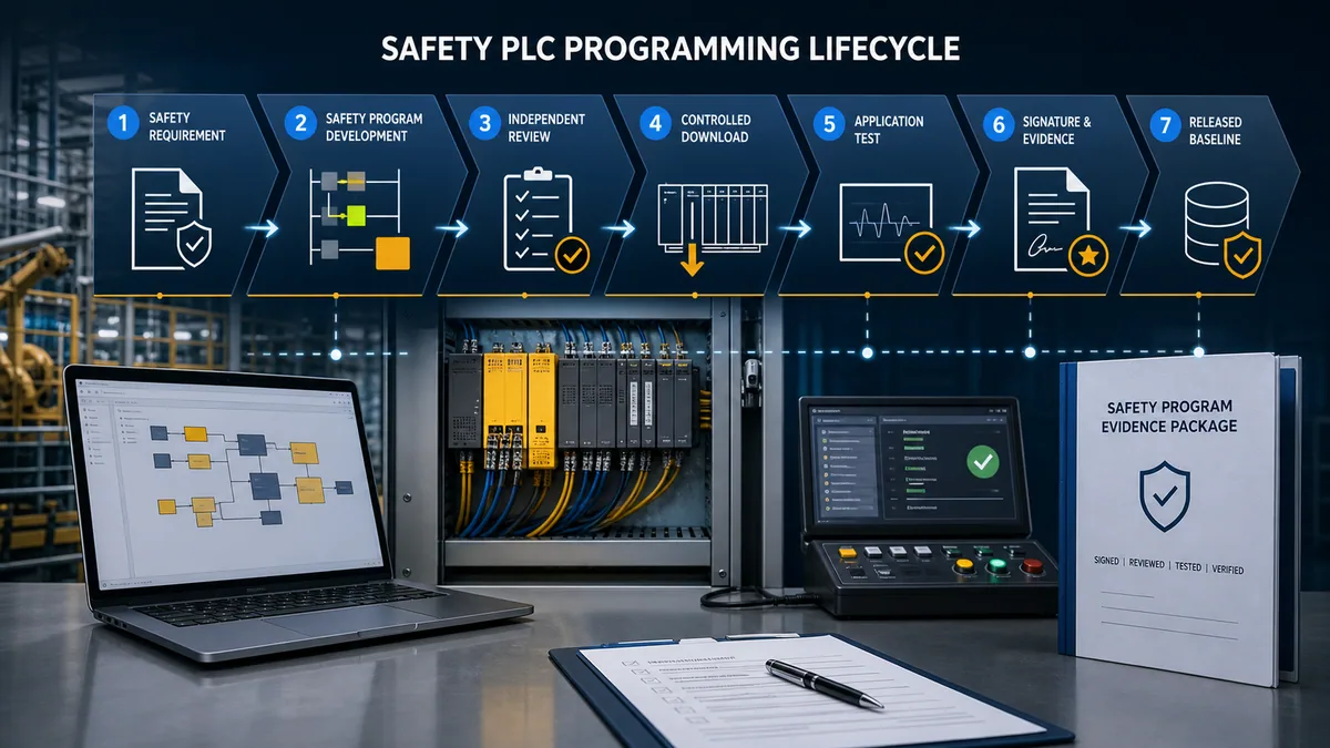
Step 1: freeze testable safety requirements
Give every safety function a unique identifier. Record its triggers, modes, safe state, affected hazards, response time, reset/restart rules, interface signals, fault reactions and required performance. Resolve vague statements before coding. A requirement that cannot produce an acceptance test is not finished.
Step 2: define architecture and data contracts
Map each function from input through logic and output to the hazard. Record shared resources, safe networks, standard/safety interfaces and time budgets. Identify whether one function’s reset, mode or zone status can affect another. Define status data so “healthy,” “ready,” “reset required,” “faulted,” “stopped” and “permitted to start” remain distinct.
Step 3: develop within the certified environment
Use supported hardware, firmware, engineering software, safety options and approved instructions. Do not infer support from a similar CPU name. Configure safety task periods, watchdogs, I/O reaction times and network update assumptions deliberately. Keep standard logic from writing safety-owned outputs or bypass states.
Step 4: structure the program for review
Prefer small function-oriented blocks, explicit states, bounded timers and documented parameters. Separate device evaluation, mode logic, safety-function decision, reset handling, output control and diagnostics. Avoid hidden latches whose set/reset priority is unclear. Avoid automatic conversions between standard and safety data unless the platform safety manual explicitly supports the path.
Step 5: verify against the requirements
Review every requirement-to-code trace, including negative cases and fault behavior. Use an independent reviewer to the degree required by the standard, project plan and organization. Verify library versions and block signatures. Static review is necessary but cannot replace running tests.
Step 6: control download and establish identity
Follow the vendor’s safety workflow. Record controller identity, hardware/firmware versions, safety tool version, project hash or safety signature, protected state, date, author and reviewer. Some platforms permit controlled online edits only under particular states; others cause a signature to be removed or require new acceptance. Never generalize one vendor’s workflow to another.
Step 7: test and validate the installed function
Test normal demand, every operating mode, reset/restart, credible faults, timing, final elements and the machine response. Close deviations or formally revise the requirements. A successful program simulation is pre-test evidence, not installed-machine validation.
Step 8: release and preserve the baseline
Store the exact approved project, signature, dependency versions, drawings, calculation, validation results, certificate/manual set, credentials procedure and restoration instructions. A backup that cannot be tied to the validated signature is not a trustworthy recovery baseline.
| Lifecycle artifact | Minimum useful content | Owner |
|---|---|---|
| safety requirements specification | function IDs, modes, triggers, safe states, timing, reset/restart, PLr/SIL, interfaces | safety/function owner |
| architecture record | subsystem boundaries, data paths, certificates, calculation assumptions | safety designer |
| program review | traceability, instruction/library checks, states, timing, independence evidence | author and reviewer |
| controlled download record | target identity, versions, protected state, signature/hash, date | commissioning lead |
| validation protocol | prerequisites, tests, faults, measurements, expected results | validation owner |
| released package | exact project, drawings, manuals, calculations, results, approvals | configuration manager |
| modification record | reason, impact analysis, affected functions, regression scope, new baseline | change authority |
Program patterns that make safety logic reviewable
The exact implementation is platform specific, but several design qualities are broadly useful.
Explicit safe state. Define what every safety output does on demand, detected fault, communication loss, task fault, controller restart and invalid configuration. “Off” is common, but suspended loads, pressure, stored energy and braking can require more detailed system behavior.
Separate reset from restart. Reset acknowledges that the triggering condition is cleared and that monitored prerequisites are healthy. It should not create hazardous movement. A production start should be a separate deliberate command under the machine’s control-mode rules.
Visible state transitions. Use a state model or equivalent structure for functions with modes, muting, guard locking, safe speed or coordinated zones. Reviewers should be able to identify every transition and the default response to an unexpected state.
Bounded time behavior. Timers used in a safety function require documented purpose, range, units and relationship to the total response-time budget. A timer copied from ordinary sequencing is not automatically suitable.
Fail-safe communication behavior. Define what happens when a safety connection is late, invalid, replaced, mismatched or restarted. Record addressing and replacement controls. The standard PLC should not fabricate a healthy safety status during a timeout.
Diagnostic separation. Diagnostic codes explain why a function is not ready. They do not alter the required response. A maintenance screen may show channel discrepancy and the approved inspection steps; it should never offer a bypass that the safety design did not authorize and assess.
Validation: prove the real machine, not just the logic
Validation asks whether the installed safety-related control system meets its specified safety requirements. It combines analysis and tests. The plan should be written early enough to influence design, not assembled after commissioning from whatever happened to be tested.
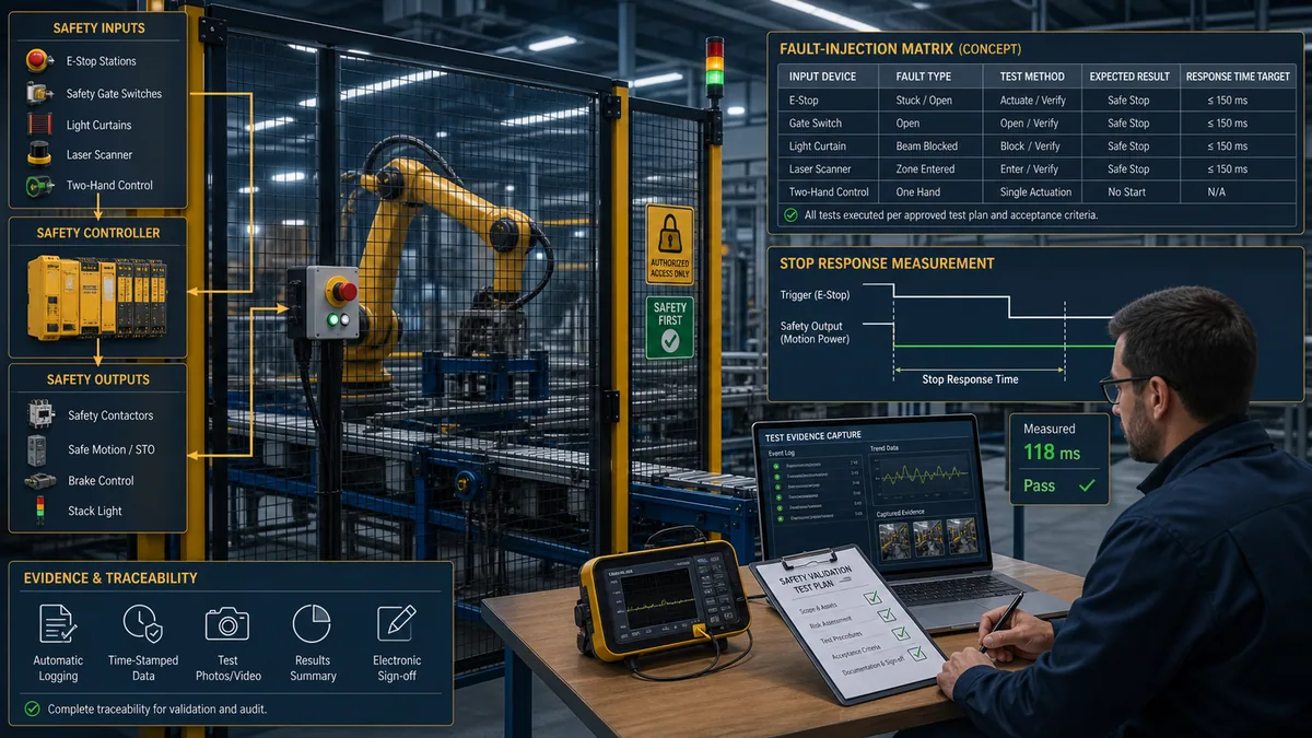
Validation coverage matrix
| Test group | Example evidence | Important boundary |
|---|---|---|
| intended demand | actuate each device in every relevant mode and machine state | observe hazard response, not only controller bits |
| reset and restart | clear the demand, reset, then issue a separate start | closing a guard or restoring power must not create unexpected motion |
| input faults | use manufacturer-supported and safely planned methods for relevant discrepancies, open/short faults or invalid states | never improvise terminal shorts on a live machine |
| communication faults | controlled loss, timeout, wrong identity or replacement scenario where applicable | verify safe response and diagnostic recovery |
| output/final-element faults | feedback mismatch, contactor/valve/drive fault scenarios supported by the plan | confirm that diagnostics match the physical failure |
| timing | measure end-to-end response under defined load, speed and conditions | PLC task time is only one part of total stopping performance |
| power cycle and restart | restore controller, field power and networks in controlled sequences | verify default states, retained data and reset requirement |
| mode combinations | setup, manual, automatic, maintenance and transitions | mode selection must not create an unassessed path |
| environmental/installation | wiring, separation, grounding, protection, device mounting and field conditions | cabinet conformity does not prove sensor mechanics or actuator response |
| documentation | compare installed versions, signature, drawings and calculation | resolve every mismatch before release |
Keep raw observations. Record the test setup, machine state, load, speed, tool identity, result, timestamp, witness and deviation. A pass/fail spreadsheet without the conditions that produced it is weak evidence. If a test cannot be conducted safely, the validation plan must define another defensible method; production pressure is not permission to create an uncontrolled fault.
Simulation is helpful earlier. Teams can rehearse state combinations, negative cases and expected diagnostics before the machine window. The interactive PLC fault lab can strengthen ordinary sequence reasoning, but it cannot inject certified I/O faults, reproduce exact safety-task execution, measure a real stop, verify a guard installation or calculate achieved PL/SIL.
Safety PLC diagnostics and troubleshooting
Good troubleshooting follows evidence from the first failed boundary. It does not begin by clearing faults repeatedly. Preserve the original event, record the exact code and state, then trace input device, channel, fail-safe I/O, safety logic, connection, output, feedback and machine response.
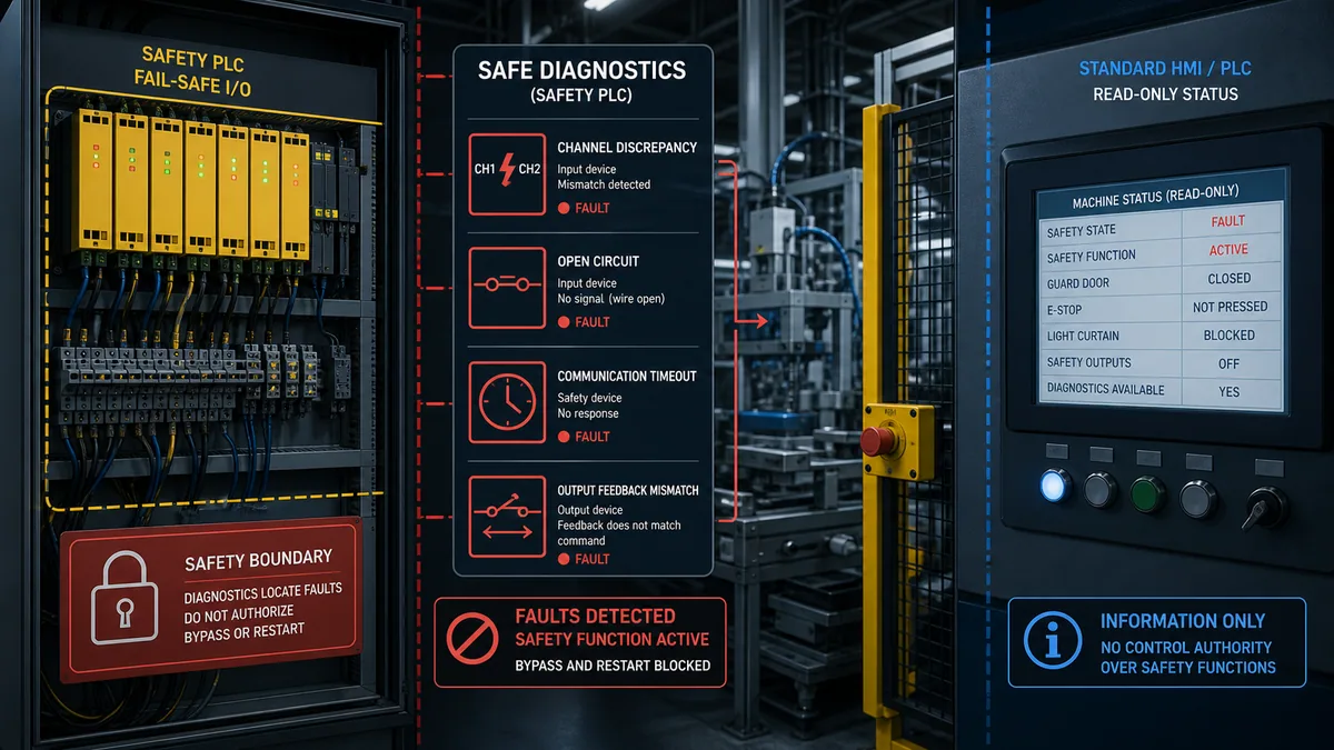
First-failed-boundary workflow
- Make the machine safe using the site’s approved energy-control and access procedure.
- Preserve timestamps, diagnostic buffers, safety connection states, device LEDs and operator report.
- Identify which safety function and zone is preventing readiness.
- Compare physical device state with raw fail-safe channel state.
- Check channel discrepancy, pulse-test, identity, connection and configuration evidence.
- Trace the evaluated device block and function state without forcing it.
- Check output command, safety output state and external-device feedback separately.
- Inspect the physical final element and affected energy/motion path.
- Repair the cause using approved methods and exact product documentation.
- Perform the required functional and regression tests before return to service.
| Symptom | Evidence to collect first | Unsafe shortcut to avoid |
|---|---|---|
| input channels disagree | device mechanics, channel states, timestamps, approved wiring diagram | jumpering channels until the fault clears |
| safety network timeout | connection identity, topology, device state, timing and recent changes | increasing timeout blindly or substituting an unverified device |
| output feedback mismatch | commanded state, output terminals under safe procedure, feedback contacts and final element | masking EDM/feedback in logic |
| reset unavailable | all demand/fault states, reset edge, visibility and restart state | converting reset to an always-true or automatic signal |
| signature changed | project identity, who changed it, tool/firmware versions and change record | accepting a new signature without impact analysis and retest |
| nuisance trips | original first-out event, environment, wiring, device mounting, timing and repetition pattern | weakening diagnostics or extending discrepancy time without assessment |
Troubleshooting is also an acquisition opportunity for a simulator product, but the boundary must stay honest. A standard PLC model can teach event latching, request/feedback separation and deliberate recovery. It cannot certify the safety path. Use the simulator to improve the engineer’s reasoning, then use the approved vendor tools, calibrated measurement equipment and site procedures on the actual system.
Worked example: guarded packaging cell
Consider a packaging cell with two access doors, one light curtain at the product infeed, an emergency-stop loop, a servo conveyor and a pneumatic pick mechanism. The standard PLC handles recipes, product tracking and production sequences. The risk assessment and machine-specific requirements define several safety functions, each with its own required response and performance.
Requirements and architecture
| Function ID | Initiating condition | Required response | Reset/restart boundary | Candidate logic architecture |
|---|---|---|---|---|
| SF-01 | either access door opens in automatic mode | remove torque-producing power from relevant axes and command pneumatic safe state | door closure does not reset; reset outside zone; separate start | safety PLC with fail-safe inputs/outputs and supported drive safety |
| SF-02 | light curtain interrupted during automatic infeed | stop affected motion within validated limit | clearing field does not restart; reset policy follows assessment | safety PLC because it interacts with zone and conveyor state |
| SF-03 | emergency stop actuated | execute specified emergency-stop response across the cell | device release does not restart; deliberate reset and separate start | same safety PLC or another assessed architecture; function remains independently traceable |
| SF-04 | maintenance mode selected | restrict permitted motion and require assessed enabling/hold-to-run behavior | mode transition controlled and indicated | certified mode and enabling-device path supported by exact platform |
The safety PLC is selected because the functions interact across zones, safe drive behavior and restart states. It is not selected merely because a row in the risk assessment produced a particular PLr. A relay-based solution might also be possible, but it would require a defensible architecture and could become harder to maintain as interactions grow.
Program organization
The team assigns one block and test set per safety function. Device evaluation remains separate from zone logic. The standard PLC sends production requests; the safety task determines whether any safety-owned output may be active. The safety system publishes explicit read-only states such as Zone1_Demand, Zone1_ResetRequired, Zone1_Fault, Zone1_ReadyForStart, and SafetySignatureMatch. The standard PLC clears ordinary run commands when a demand appears and never writes a signal that bypasses a device.
Timing budget
The end-to-end response budget includes sensor response, input processing, safety task/network timing, output response, drive or contactor behavior and mechanical stopping time. The team measures the actual machine under the defined operating conditions. It does not treat the PLC scan time as total stop time or copy a value from the illustration above.
Validation and handover
Validation exercises every function in all relevant modes, selected credible faults, communication loss, feedback mismatch, power cycles, reset/restart and stopping performance. The released package records hardware, firmware, engineering-tool and library versions, the final safety signature, requirements, calculation, reviewed program, drawings and results. Maintenance receives diagnostic guidance that points to evidence without instructing anyone to bypass the function.
This is the kind of reasoning that can be rehearsed in the PLC troubleshooting simulator: request, permissive, command, feedback, timeout, first-out and recovery. The cell’s safety validation still occurs on the approved hardware and installed machine.
Platform evidence: compare manuals, not marketing labels
Major platforms implement safety differently. Siemens documents SIMATIC S7-1200F/S7-1500F safety programming in TIA Portal; Rockwell documents GuardLogix safety tasks, locking, signatures and certified instruction sets; Pilz documents PSS 4000 hardware, PAS4000 and product-specific safety constraints; ABB publishes AC500-S certification and safety manuals. These examples prove that capable products exist. They do not make their workflows interchangeable.
| Evidence item | Why it matters | Check before design freeze |
|---|---|---|
| certificate and report | defines standards, product variants, capability and conditions | exact catalogue numbers, revisions and regional validity |
| safety manual | contains mandatory architecture, parameter and lifecycle constraints | correct revision for hardware/firmware/tool combination |
| approved instruction/library list | defines what can run in the safety application | block version, signature and usage restrictions |
| safety I/O manual | defines channel, pulse, fault and output assumptions | exact module, wiring mode, loads and test-pulse compatibility |
| safe network manual | defines address, timing, topology and replacement controls | device identity, watchdog/reaction and commissioning process |
| release notes | exposes fixed defects and compatibility boundaries | known anomalies that affect the planned application |
| restoration procedure | determines whether a failed unit can be replaced safely | identity assignment, signature verification and regression tests |
Avoid generic hardware claims such as “all safety PLCs have two physical CPUs” or “every safety input pulse-tests every channel.” Certified architectures vary by family and generation. Describe the safety properties required of the subsystem; use the exact manual to explain how a chosen product achieves them.
Managed change and regression testing
Safety systems change after release: sensors become obsolete, firmware is updated, a guard moves, a new product mode is added, timing is adjusted, or ordinary PLC code changes the interface. Every proposed change needs an impact assessment before implementation.
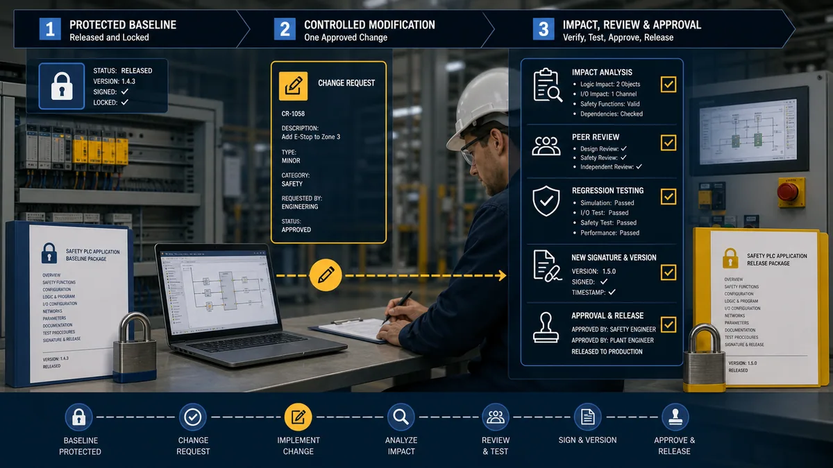
The assessment asks what hazards, functions, modes, interfaces, calculations, device data, timing and documents can be affected. Changing a standard PLC tag may still be safety relevant if it feeds a mode request or status contract. Updating firmware may alter certified combinations or require a new project conversion. Replacing a sensor with the “same type” can change output behavior, diagnostic compatibility, response time or reliability data.
| Change | Minimum questions | Likely evidence affected |
|---|---|---|
| safety code edit | which functions and states change; does the signature change; what independence is required? | requirements, review, functional/fault tests, signature and release package |
| standard code/interface edit | can safety-bound requests, modes, reset or displayed state change? | interface specification and relevant integration/regression tests |
| firmware/tool update | is the combination certified; are conversion notes or anomalies relevant? | compatibility matrix, compiled project, signature, validation scope |
| safety device replacement | do certificate, wiring, diagnostics, timing and reliability assumptions remain valid? | calculation, drawings, device tests and spare procedure |
| mechanical change | do stopping time, reach, visibility, guard geometry or energy change? | risk assessment, safety requirements and measured validation |
| timing/parameter change | does it affect reaction, discrepancy, filtering or proof-test assumptions? | timing budget, rationale, calculation and targeted fault tests |
Preserve the old released baseline and its evidence. Create a new baseline only after the approved change, review and required verification/validation are complete. Do not overwrite the prior project and call the file name “final.”
Common safety PLC mistakes
Treating the controller rating as the machine rating
A controller advertised or certified for use up to SIL 3 or PL e is a capable component under stated conditions. The installed function still requires its complete architecture, calculation and validation.
Selecting by PL/SIL alone
Required performance and controller type are separate decisions. Function count, interaction, technology, diagnostics, safe communications, maintainability and certified application all influence architecture.
Letting reset start the machine
Reset should restore readiness after the demand and faults are cleared. A separate deliberate start should initiate hazardous motion unless an applicable assessed design explicitly permits something else.
Crediting the standard PLC accidentally
If the safety logic depends on a standard bit becoming true at the right time, document why that path is acceptable. Prefer logic that treats standard data as untrusted requests and defaults safely when it is invalid.
Using simulation as acceptance evidence
Simulation can find logic errors and prepare test cases. It does not prove electrical faults, safety communication, real timing, final-element behavior or the installed hazard response.
Clearing faults before collecting evidence
Repeated reset and power cycling can destroy the first-out sequence. Preserve diagnostic buffers, timestamps and physical states before recovery.
Weak configuration identity
A project file without exact target, firmware, tool/library versions and safety signature cannot be tied confidently to the validated machine.
Generic maintenance bypasses
A bypass is a designed operating mode or risk-control measure only when it is explicitly assessed, authorized, indicated, limited and validated. A jumper or forced bit used to keep production running is not a troubleshooting technique.
Frequently asked questions
What is the difference between a safety PLC and a standard PLC?
A standard PLC is intended for ordinary automation. A safety PLC provides certified mechanisms and a controlled engineering workflow for implementing safety-related logic within defined conditions. The safety PLC is still only one part of the complete safety function, and its certification does not validate the application.
Does PL d or SIL 2 always require a safety PLC?
No. PLr or SIL specifies required performance for a complete safety function, not a universal controller type. Select and evaluate the sensor–logic–output architecture using the applicable standard, certificates and safety manuals. A relay or configurable controller may be valid; a safety PLC may be preferable for complexity or lifecycle reasons.
Can a standard PLC be used with a safety relay?
Yes. A common architecture uses a safety relay for the credited safety function and a standard PLC for production control and read-only diagnostics. The standard PLC must not bypass the relay, energize the protected final element through another path, or create automatic restart.
Can a standard PLC achieve Performance Level c?
Do not assume it can merely from field reliability or because it has operated without failures. ISO 13849 architecture and systematic requirements apply, and DGUV Test has published a specific caution about treating ordinary complex electronics as well-tried Category 1 components. A competent designer must assess the exact architecture and applicable edition.
What software is needed to program a safety PLC?
Use the exact vendor engineering environment, safety option, version and licensed components supported for the selected controller and firmware. You also need current safety manuals, approved instruction/library information, controlled access, review and validation processes. Ordinary PLC programming experience alone is not evidence of functional-safety competence.
Can safety PLC logic be edited online?
It depends on the platform, protected state, signature and certified workflow. Some systems permit limited controlled edits under defined conditions; an edit may invalidate or remove a safety signature and require revalidation. Follow the exact product safety manual and record the resulting application identity.
How should a standard HMI display safety status?
Use explicit read-only states such as demand active, reset required, faulted, ready for start, output off and connection invalid. Define polarity, update behavior and timeouts. Do not label an ambiguous bit “safe,” and do not give the HMI control authority that the safety design has not assessed.
Can a safety PLC simulator validate the safety program?
No. A simulator can support learning, code review and test-case preparation. It cannot reproduce the certified hardware/firmware chain, real fail-safe I/O faults, safe network behavior, final elements, environmental conditions or measured machine response. Installed validation remains necessary.
Why does a safety PLC show a channel discrepancy fault?
The two evaluated channel states did not change within the configured and permitted relationship, or the system detected a wiring/device condition represented by that diagnostic. Preserve the evidence and inspect the exact device, channel states, timing, wiring and parameterization using the product manual. Do not jumper the channels to clear it.
What records should be kept after commissioning a safety PLC?
Keep the risk assessment, safety requirements, architecture and calculation, exact hardware/firmware/tool/library versions, certificates and manuals, reviewed source project, safety signature or equivalent identity, drawings, validation protocol and raw results, deviations, approvals, backup/restore procedure and future change history.
Sources, review scope and limitations
This page was technically reviewed against the following primary sources on 30 August 2026:
- ISO 12100:2010 — machinery risk assessment and risk reduction
- ISO 13849-1:2023 — safety-related parts of control systems, general design principles
- ISO 13849-2:2012 — validation by analysis and testing
- IEC 62061:2021 — functional safety of safety-related control systems for machinery
- IEC 62061:2021 Amendment 1:2024
- IEC 62061:2021 Amendment 2:2026
- IEC 60204-1:2016 with Amendment 1:2021 — electrical equipment of machines
- IFA/DGUV SISTEMA — ISO 13849-1 evaluation tool and supported-edition notes
- DGUV Test Information 06 — Can PL c be achieved with a standard PLC?
- Siemens — Programming Guideline Safety for SIMATIC S7-1200/1500, V1.6, July 2024
- Rockwell Automation — Logix 5000 Controller Safety Application Instruction Set, September 2025
- Rockwell Automation — GuardLogix 5570 and Compact GuardLogix 5370 Safety Reference Manual, October 2024
- Pilz — PSS 4000 safety manual and current product documentation index
- Pilz — PAS4000 software platform for safety and automation
- ABB — AC500-S functional safety certification and manual boundary
- ABB — Pluto programmable safety controller scope
This is an educational selection and lifecycle guide, not a machine-specific risk assessment, PL/SIL calculation, wiring drawing, safety requirements specification or validation report. It cannot decide the required safety functions, PLr, SIL, stop behavior, test method or legal conformity for a machine. Apply the standards and law adopted in the relevant jurisdiction, the applicable Type-C standard, and the exact certificates and manuals for every installed product. Work on hazardous machinery requires competent people, controlled access and the site’s approved energy-control procedures.


