Learn PLCs free

Version 1.1 · reviewed 30 August 2026

PLC Commissioning Checklist TemplateFAT, SAT, I/O & Handover Pack

Download a 49-test master checklist and eight supporting resources that connect requirements, hardware, software, field evidence and as-left recovery. Preview everything, download without signup and adapt it to the project's controlled procedures.

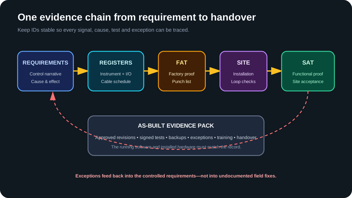
Requirements flow through engineering registers, FAT, site loop checks and SAT into an as-built evidence pack
Stable IDs let a requirement point to a signal, cause, test result and exception without relying on someone's memory.

Direct answer

What belongs in a commissioning checklist?

A commissioning checklist is a controlled evidence register—not a memory aid with boxes to tick. Each test should identify its prerequisite, approved requirement, verification method, expected result, evidence, responsible owner, witness, status, exception and retest. For a PLC system, the scope normally spans document and version control, exact hardware/software identity, pre-power inspection, controlled energization, I/O and network proving, program execution, normal and failed behavior, recovery, backups and as-built handover.

This template is intentionally controls-specific. The broad search phrase also returns HVAC, building and general equipment forms, but those do not test PLC task execution, raw-to-normalized I/O, command-versus-feedback, network quality, warm restart or the identity of the running software. Add the applicable electrical, mechanical, process, cybersecurity, regulatory and safety records instead of stretching one spreadsheet beyond its competent scope.

Checklist fieldPurposeWeak entryUseful entry
Requirement IDTrace test to approved intentMotor worksFDS-MTR-014 / C&E row 23
Expected resultDefine pass before executionLooks OKRun feedback true within approved timeout; no fault
EvidenceMake result reproducibleScreenshotTrend CX-052-01, event export and witness initials
StatusUse one controlled vocabularyDonePass / Fail / Blocked / Accepted exception
ExceptionPreserve incomplete or divergent workFix laterP-017, impact, owner, due date and retest link
As-left stateIdentify what was acceptedLatest fileUploaded project, comparison result, version and hash
Nine-gate PLC commissioning evidence flow from approved requirements through FAT, site readiness, SAT and handover
Progress on evidence, not calendar pressure. Every gate needs explicit entry criteria, blocking conditions, an authorized release and a recoverable record.

Before functional testing

Pre-power inspection and controlled energization

Do not turn the main disconnect merely because software is ready. The responsible electrical and site teams must determine the inspection, test instruments, exposure controls, permits and sequence for the installation. The controls record should link to those approved results, confirm the exact PLC system identity and define the safe initial state before ordinary outputs can be enabled.

De-energized PLC control panel pre-power inspection showing supply protection, PLC rack, 24 volt power supply, terminal blocks, grounding and controlled drawings
The checklist records the approved inspection evidence; it does not replace the electrical procedure, competent person or project acceptance limits.

Pre-power evidence to reference

BoundaryControls checkEvidenceProgression blocker example
Document identityPanel, drawings, I/O and network registers refer to the same systemControlled revisions and redline logUnknown or conflicting panel identity
Installed hardwareController, modules, power supplies, switches and interfaces match manifestCatalogue/firmware asset recordUnsupported module or firmware chain
InstallationIdentification, segregation, terminals and field interfaces are ready for approved inspectionSigned inspection recordsUnterminated or untraceable conductor
Energy controlsRequired permits, isolation boundaries, test roles and stop conditions are currentSite authorization referenceNo authorized energization plan
RecoveryPre-change PLC, HMI, drive and network baselines are recoverableArchive, comparison and restore notesOnly unknown laptop copy exists
Initial stateModes, output inhibits and equipment conditions prevent unintended operationPre-start state checklistActuator could move on power restoration

Treat testing with restored energy as a separate controlled state

In US general-industry servicing scope, OSHA 1910.147 defines control-circuit devices such as pushbuttons as different from energy-isolating devices and provides a specific sequence when lockout or tagout must be temporarily removed for testing or positioning. Other jurisdictions and activities differ. The commissioning sheet should reference the actual employer procedure; it should never summarize that procedure into “LOTO complete” and imply blanket permission for energized diagnosis.

Point-to-point proof

PLC I/O and loop-check checklist

A loop check follows one signal end to end. For an input, start with an approved physical stimulus and prove the field device, junction/terminal path, module channel, raw tag, normalized application state, HMI indication and downstream consumer. For an output, prove the software command, mapped channel, field signal, device response and independent feedback. Do not use the output command as proof that the final device or process moved.

PLC digital and 4 to 20 milliamp loop-check path from field device through junction box and I/O terminals to controller and HMI evidence
Keep the raw observation, normalized application value, command and feedback as distinct evidence points. That separation makes polarity, scaling and stale-data faults diagnosable.

Record more than pass or fail

Signal classStimulus / commandObserveFailure behaviorEvidence
Digital inputApproved field open/closed statesModule point, raw tag, normalized state and displayBroken-wire or contradictory-state expectationPhotos/drawing reference plus timestamped tag trace
Digital outputControlled command with equipment readyMapped point, field signal, device action and feedbackInhibit, module fault and missing-feedback responseCommand/feedback timeline and witness
Analog inputTraceable points across required rangeRaw count, scaled unit, quality, alarm and historyUnder/over-range, bad quality and stale valueAs-found/as-left table and instrument reference
Analog outputTraceable commanded pointsCommand, raw output, field signal, position/value feedbackOpen circuit, saturation and device faultCommand-versus-measurement table
Network valueKnown payload and state transitionsType, byte order, scaling, timestamp/quality and consumerTimeout, reconnect and stale-data policyPacket/device diagnostics and application trace

Preserve as-found and as-left values

If a channel is rewired, a range is corrected or scaling is changed, record the initial observation before correction. Then identify the authorized change and repeat the test. Replacing a failed result with the final pass hides the evidence needed to understand design drift, workmanship, later failures and whether adjacent points require review.

Nine-gate workflow

Use the checklist as a stage-gate plan

The master CSV contains 49 editable tests grouped into the gates below. It does not prescribe universal acceptance limits or a universal sequence: the approved project protocol does that. The gates make hidden assumptions visible and stop one successful demonstration from being mistaken for complete acceptance.

GateDecisionMinimum coverageRelease evidence
G0Control the scopeApproved specification, roles, hazards, acceptance authority and change processSigned plan and requirement trace
G1Review the designHardware/software manifests, drawings, I/O, networks, program structure and test casesResolved review record
G2Inspect before powerInstallation, identification, segregation, protection, bonding and recoverable backupsAuthorized pre-power release
G3Energize deliberatelyBriefing, permits, supplies, diagnostics, network identity and safe initial stateControlled energization record
G4Prove I/O and loopsRaw-to-normalized inputs, outputs, analog range, quality, timeout and as-left valuesPoint-to-point evidence
G5Execute FATModes, sequences, failures, restart, performance, HMI and exception evidenceWitnessed factory record
G6Reconcile the siteFAT closeout, installation differences, utilities, interfaces and operating readinessSite-ready authorization
G7Execute SATInstalled normal, abnormal, integration and contract-specific performance casesWitnessed site record
G8Hand over controlTemporary-condition removal, exceptions, running backups, as-builts and trainingAccepted as-left package

Define hold points before the test begins

A hold point is a condition that prevents progression until the named acceptance authority releases it. Examples include an unapproved drawing, unresolved protective bonding result, incorrect controller identity, unavailable backup, safety-validation blocker or FAT exception that affects site energization. Record who can release the hold, what evidence is required and what downstream tests become invalid if the hold is ignored. “We needed to keep moving” is not a technical disposition.

Separate pass, blocked and accepted exception

Pass means the predefined result was observed. Fail means it was not. Blocked means the test could not be validly executed because a prerequisite or environment was missing. Accepted exception means the authorized parties knowingly accepted a documented divergence with its impact and obligations. These states should never be collapsed into “complete,” because they drive different decisions, retests and residual risk.

Download pack

Start with the document you own

CSV opens in Excel, LibreOffice and Google Sheets. Preserve revision, owner and status columns when adapting the files.

Prove behavior before site pressure

PLC FAT checklist: normal, abnormal and recovery tests

Factory acceptance should test the approved automation behavior while faults can still be injected without disrupting an installed process. Start with project identity and test readiness; execute normal modes and transitions; then prove the defined responses to missing feedback, failed sensors, lost communications, utility loss, restart and recovery. A build with no compiler errors is not evidence that the machine requirement is correct.

PLC factory acceptance test bench injecting ordinary command, permissive, feedback timeout, stuck sensor, communication loss and power-cycle cases
Write expected results before injecting the condition. Capture the state, command, feedback, timer, alarm, recovery and regression evidence under one test ID.

A practical fault-injection matrix

Injected conditionExpected control resultExpected diagnosticRecovery question
Start and stop togetherDefined dominant condition winsCommand reason remains explainableIs a new start required after release?
Permissive false before startRun request remains blockedSpecific blocking condition is visibleDoes clearing alone start equipment?
Feedback missing after commandCommand follows approved timeout policyFirst-out feedback fault with elapsed contextWhat reset and retry conditions apply?
Sensor stuck true or falseSequence holds, degrades or stops as specifiedPlausibility or timeout identifies the signalCan recovery skip or duplicate product?
Network value becomes staleConsumer uses defined stale-data behaviorQuality/timeout identifies interface and ageIs reconnect bumpless and state reconciled?
Controller or device power cycleNo unintended start; state follows retention policyStartup/recovery event is retainedWhich operator acknowledgement is required?
Output inhibited or device faultedCommand and physical state remain distinguishableModule/device fault and missing response are visibleIs the cause cleared before reset?
Task exceeds timing budgetWatchdog/degraded behavior follows platform designTask overlap or execution evidence is availableIs the root cause removed before returning to service?

Use a simulator for logic evidence, with a disclosed boundary

A simulator is useful for repeating command, permissive, timer, sequence and selected fault cases before FAT. It does not prove installed wiring, firmware-specific behavior, network timing, device dynamics, protection or safety. PLC Simulation Software is operated by the same publisher as this site; use its browser exercises only as preparation for the controlled vendor and physical tests in the project protocol.

Practise a fault case in the simulator →

Installed-system proof

SAT, site integration and handover

Site acceptance is not “repeat FAT with real outputs.” Reconcile what changed during shipping and installation, prove field I/O and utilities, test upstream/downstream handshakes, involve operations and maintenance, close or accept exceptions, remove temporary commissioning conditions and archive the system that is actually running. Site integration tests should identify both sides of every interface and the behavior when either side is unavailable or contradictory.

Controls, operations and owner representatives witnessing PLC site acceptance on an installed conveyor and pump system with punch list and backup evidence
Acceptance is a decision supported by traceable results, not a photograph of a running machine. Preserve open items, authorized dispositions and the exact as-left software.

What changes between FAT and SAT?

Evidence layerFAT can establishSAT / SIT must establishStill separate
Software behaviorConfigured modes, sequences and injected failuresBehavior with installed devices and actual interfacesFuture untested modifications
I/OSimulated or bench signal mappingField identity, polarity, scaling, quality and responseElectrical certification and calibration scope
NetworksConfigured devices and laboratory fault casesInstalled topology, names, timing, load and recoveryEvery future traffic or security condition
Process/mechanicsModelled or substituted statesReal utility, load, sensor and actuator responseConditions outside the approved test envelope
OperationsHMI and alarm behavior with test teamRole-based operator and maintenance use and recoveryOngoing competence and procedure governance
SafetyOrdinary interface behavior where authorizedReference to completed project-specific validationReplacement for qualified safety validation

Do not invent a universal reliability run

A 24-, 48- or 72-hour run is not automatically appropriate merely because another project used it. The contract must define duration, production state, allowable stops, exclusions, restart of the clock, data source and acceptance calculation. Record the operating envelope and disturbances so an apparently successful run is not used as evidence for loads or recipes that were never exercised.

How the files fit together

  1. 1.Write testable requirementsUse the control narrative and cause-and-effect matrix before building logic. Give each requirement an ID.
  2. 2.Create the registersAlign instruments, I/O, cables, terminals, ranges and drawing references. Resolve conflicts before FAT.
  3. 3.Prove offline and at FATTest normal operation, failures, restarts and communication loss. Store evidence beside each test ID.
  4. 4.Reconcile the installationAt site, compare the actual panel and field wiring with the controlled registers before functional tests.
  5. 5.Close with SAT evidenceRecord as-left values, clear forces and bypasses, archive the running software and control every exception.

Quality rules worth keeping

  • One owner: each row needs someone responsible for closing it.
  • One status vocabulary: define Draft, Ready, Pass, Fail, Blocked and Accepted Exception.
  • No silent deletion: retire a row with a reason instead of erasing the evidence.
  • As-found and as-left: preserve both when calibration or correction changes a value.
  • Separate safety validation: reference the approved record; do not reduce it to a generic FAT checkbox.
  • Controlled handover: the archive must match the program and hardware actually running.

Need the workflow behind the sheets?

Read the functional design specification, cause-and-effect matrix and site acceptance test references.

When a test fails

Commissioning troubleshooting and exception control

Preserve the first symptom before resetting, forcing, downloading or cycling power. Record the test ID, time, operating state, controller/device diagnostics and last action. Then isolate one boundary at a time: requirement and identity, task and logic, I/O and network, field circuit, device/mechanics and process result. One controlled observation should eliminate a layer; random edits make the evidence weaker.

PLC commissioning troubleshooting evidence ladder from requirement and project identity through logic, I/O, field circuit, mechanics and process result to rollback archive
The rollback archive is connected to every layer because a commissioning change can affect configuration, state, interfaces and recovery—not only the rung being watched.

Symptom-to-evidence matrix

SymptomFirst observationNext boundaryAvoid
Cannot go onlineExact controller, route, project/firmware and security stateEngineering workstation and network pathDownloading the open file to see if it connects
Logic visible but inertController mode, task, program, main routine and call pathEnable conditions and scheduler evidenceRewriting a rung that never executes
Input LED changes; tag does notChannel diagnostics, mapping, raw tag and update qualityTerminal/wiring/device under approved procedureChanging addresses until a bit moves
Output command true; device idleCommand, mapped point, module state, inhibit/force and feedbackNetwork, starter/drive, field circuit and mechanismCalling the command bit “motor running”
Sequence stallsCurrent state, transition conditions, timers and first-out faultSensor/process condition and requirementWriting the next state manually
Restart differs from FATPower-cycle type, retained state, startup task and device reconnect orderVersion/site environment differencesAdding retention without a recovery analysis
Intermittent failureTime-correlated event, task, network, power and process dataRepeatable controlled stimulusResetting before collecting the first event

Control every punch-list item

Give each exception a stable ID, affected requirement and test, as-found evidence, impact, temporary condition, owner, due date, disposition, approval and retest. If the item changes hardware, logic, configuration or a setpoint, update the controlled baseline and identify which completed tests must be repeated. Never delete the failed row after the correction; link it to the passing retest.

DispositionMeaningRequired evidence
Correct and retestObserved result did not meet approved expectationAuthorized change, new version, original case and regression pass
BlockedPrerequisite or environment prevents a valid testBlocking condition, owner, next action and rescheduled test
Accepted exceptionAuthorized parties accept a known divergenceImpact, affected scope, obligation, expiry/review and approver
Duplicate / not applicableRow does not apply or is proved elsewhereReason and link to controlling requirement or evidence
Deferred scopeWork is moved to a later controlled phaseContract/change reference, owner, entry criteria and hold-point impact

A minimal evidence pack

At handover, an independent engineer should be able to identify the approved requirement, installed hardware, running software, field signal, test result and unresolved exception without reconstructing the project from email. At minimum, retain approved specifications, as-built drawings, I/O and instrument registers, network schedules, backups, FAT/SAT records, calibration/loop evidence, punch lists, training records and the final change log.

Review the pack after the first real project and send corrections through the corrections process. Versioned improvements make this asset more useful than a static checklist copied between jobs.

Handover objectIdentity to retainAcceptance question
Running control softwareController/HMI/drive/network version, project, upload/compare and hash where supportedDoes the archive match what is running as-left?
Hardware and firmwareCatalogue, series, firmware, module slot, device identity and replacement constraintsCan a future maintainer identify a compatible replacement?
Engineering recordsApproved and as-built drawings, I/O, instrument, cable, alarm and interface revisionsDo all tags and interfaces resolve without email archaeology?
Test evidenceRequirement, test ID, expected/observed, witness, data and exception linksCan an independent reviewer reproduce the acceptance decision?
Temporary conditionsForces, bypasses, temporary wiring/code/accounts and approved residual exceptionsIs every temporary state removed or explicitly controlled?
Recovery packageTool/OS/licence needs, credentials process, backups, restore and rollback instructionsHas recovery been assessed for the exact platform and site?
People and supportRole-based training, procedures, spares, warranty and escalation contactsCan operations and maintenance recognize and respond to failures?

Reference or share this toolkit

If a training note, project standard or article points readers to these files, link to this versioned landing page so they also receive the use boundary, updates and corrections—not an orphaned spreadsheet.

https://plcprogramming.io/tools/commissioning-toolkit

Answer surface

PLC commissioning checklist FAQ

What is a commissioning checklist?

A commissioning checklist is a controlled test register that identifies prerequisites, the requirement being proved, the verification method, expected result, evidence, owner, witness, status, exception and retest. A useful checklist is project-specific and traceable; a list of generic yes/no questions is only a starting template.

What should be included in a PLC commissioning checklist?

Include document and version control, exact hardware and software identity, pre-power inspection, controlled energization, digital and analog I/O checks, network and data mapping, program execution, modes and sequences, permissives and interlocks, fault injection, restart behavior, HMI and alarms, performance, backups, exceptions, training and as-built handover. Safety validation must remain a separate qualified record.

What is the difference between FAT, SAT, SIT and commissioning?

FAT proves the specified automation system at the supplier or integrator before site deployment. SAT proves the installed system at site. SIT focuses on integrated interfaces and systems. Commissioning is the broader project activity that can include inspection, loop checks, controlled energization, functional testing, startup and handover. The current ISA-105 page notes that ANSI/ISA-62381-2026 covers FAT, SAT and SIT but does not itself cover loop checks or commissioning.

Is a PLC commissioning checklist the same as an electrical commissioning checklist?

No. They overlap at panel identity, supplies, protection, bonding, wiring and controlled energization, but electrical inspection and testing require their own competent-person procedures and acceptance limits. The PLC checklist continues through task and program execution, I/O meaning, data mapping, sequences, alarms, communications, failure behavior and software recovery.

When should a PLC backup be taken during commissioning?

Capture a recoverable baseline before controlled changes, then archive tested milestones and the final as-left running system. Record controller and tool versions, project identity, upload/compare result, included device configurations, checksums where supported and restoration instructions. A file on a laptop is not a proven backup until the applicable restore path has been assessed and tested safely.

How should PLC I/O be commissioned?

Start from the approved I/O and loop schedule. Trace each field state through the terminal and module channel to the raw tag, normalized application value, HMI indication and historian or interface where applicable. For outputs, separate the controller command from module state, field signal, device action and independent feedback. Retain as-found and as-left values plus traceable test equipment references.

What failure tests belong in PLC FAT and SAT?

Select tests from the approved requirements and risk process. Common ordinary-control cases include simultaneous commands, missing or contradictory feedback, sensor stuck or bad quality, network timeout, utility loss, blocked downstream equipment, task overrun, warm restart, power cycle and recovery after a cleared fault. Do not invent or execute hazardous tests outside the authorized procedure.

How should commissioning punch-list items be classified?

Classify each item by impact on safety, authorization, test validity, operation, maintainability, documentation and schedule. Give it a stable ID, owner, due date, disposition, affected tests and retest evidence. The contract and acceptance authority define which items block progression; this template does not create a universal A/B/C punch-list rule.

Can PLC simulation replace commissioning?

No. Simulation can exercise logic, sequences, timer behavior, operator commands and selected failure cases before site work. It cannot validate installed power, protective bonding, field wiring, device configuration, network timing, machinery, process dynamics or safety functions. Use simulation evidence to improve FAT and SAT tests, not to claim the physical system is commissioned.

What belongs in the final PLC commissioning handover pack?

Retain approved specifications, as-built drawings and registers, exact hardware and software manifests, running PLC/HMI/drive/network backups, compare or checksum evidence, FAT/SAT/SIT and loop records, calibration evidence, alarm and interlock results, cleared or accepted exceptions, change history, training records, spares and recovery instructions. The archive should let an independent engineer identify the accepted as-left system.
Primary-source map

Standards, safety and platform sources

Reviewed 30 August 2026. These sources define their own scopes; none endorses this independent template. Public catalogue/help pages were used to identify current editions, responsibilities and platform operations. Purchase and apply the standards, manuals, contract and jurisdiction required for the actual installation.

  1. ISA-105 standards series — current FAT/SAT/SIT, loop-check and calibration family overview.
  2. ANSI/ISA-62381-2026 / IEC 62381:2024 — current process-industry FAT, SAT and SIT publication.
  3. ISA standards news — 2026 publication notice for ISA-62381 and ISA-62382.
  4. ISO 13849-2:2012 — current published machinery safety-related control validation edition, with revision in development.
  5. IEC 62061 — machinery functional-safety lifecycle and validation context.
  6. OSHA 29 CFR 1910.147 — US general-industry hazardous-energy requirements within its scope, including testing/positioning provisions.
  7. OSHA 29 CFR 1910.333 — US selection and use of work practices for electrical safety within its scope.
  8. NIST SP 800-82 Rev. 3 — OT security, change, access, resilience and operational-constraint context.
  9. ISA/IEC 62443 series — industrial automation and control-system security lifecycle and program context.
  10. IEC 61131-3:2025 Edition 4 — current PLC programming-language suite boundary.
  11. Rockwell Logix Designer download guidance — controller selection and download-impact warning.
  12. Rockwell project/controller correlation — upload, download and mismatched-project decision boundaries.
  13. Omron Sysmac Studio Operation Manual W504 — synchronization, compare, controller backup and restore operations.
  14. Siemens STEP 7 V21 programming guidance — current Siemens project/block workflow.
  15. CODESYS Task Configuration — task type, program calls, priority, interval and watchdog context.