Current Transformer Guide: Ratio, Burden, Wiring & Safety
Select and commission a current transformer using ratio, window size, accuracy, burden, polarity and secondary safety—not primary current alone.
A current transformer (CT) reproduces a scaled secondary current proportional to the primary conductor current. To select one correctly, specify the application, primary/secondary ratio, continuous and fault current, conductor/window size, frequency, accuracy class and allowable burden. During service, never leave a conventional CT secondary open while primary current may flow.
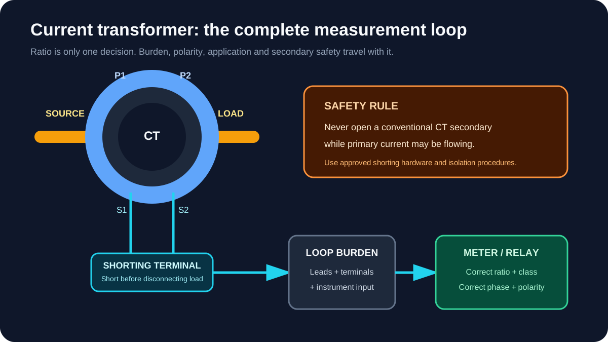
That final rule is critical: an open CT secondary can develop a dangerous voltage and damage insulation. Use approved shorting terminals and site procedures; isolate the primary before changing secondary wiring.
Download the current-transformer selection worksheet (CSV)
CT selection in one table
| Parameter | Design question | Why it matters |
|---|---|---|
| Application | Metering, protection or control indication? | Accuracy and saturation requirements differ |
| Ratio | What primary range maps to 1 A or 5 A secondary? | Sets signal scale and usable measurement range |
| Continuous current | What is normal and sustained overload current? | Prevents overheating and chronic over-range operation |
| Fault duty | What fault current and duration can occur? | Protection CTs must reproduce fault current appropriately |
| Accuracy class | What error is allowed over the required range? | Metering, revenue and protection needs are not interchangeable |
| Burden | What VA/impedance do leads and devices impose? | Excess burden increases error and can drive saturation |
| Window/core | Will the conductor, busbar or cable fit? | Mechanical fit and insulation clearances are design constraints |
| Polarity | Which direction defines positive current? | Required for power, differential and directional measurements |
| Environment | Temperature, enclosure, pollution and insulation level? | Affects construction, mounting and approvals |
How a current transformer works
The primary current creates magnetic flux in the CT core. That flux induces current in the secondary winding. In the ideal relationship:
Primary current / Secondary current = Primary turns / Secondary turns
A window CT normally has one primary turn: the conductor passes once through the core. Passing the conductor through twice creates two primary turns and changes the effective ratio. Never do this casually; document the resulting ratio and verify the manufacturer's instructions.
Common rated secondary currents are 5 A and 1 A. A 400:5 CT produces 5 A at 400 A primary in its rated condition. At 200 A primary, the ideal secondary current is:
Secondary = 200 A × (5 A / 400 A) = 2.5 A
A PLC analog input normally does not accept 5 A directly. The CT may feed a compatible power meter, protection relay or current transducer that converts the measurement to an isolated analog or network signal. Verify the input type before wiring.
Metering CT vs protection CT
Metering CT
A metering CT is selected for useful accuracy around the normal operating range. Its saturation behaviour can also help limit extreme secondary current presented to meters during faults, depending on the design.
Protection CT
A protection CT must reproduce fault-current information sufficiently for the connected relay and protection scheme. Knee point, excitation characteristic, accuracy limit and transient performance may matter. This selection belongs to a protection study—not a general PLC I/O calculation.
Do not substitute a CT because the ratios match. Two 400:5 devices can have different core, class, burden and fault behaviour.
Live mini-lab
Try it: press START, then STOP
A stop-dominant seal-in rung: START latches the motor output through its own contact, and STOP breaks the circuit.
Watch the output lamp: it stays on after START until you press STOP.
Free · no signup to try · runs in your browserOpens plcsimulationsoftware.com — same team
Understanding ratio
Choose a primary rating close enough to the expected load to use the instrument's measurement range, with appropriate allowance for continuous current and future operating conditions.
Oversizing has a cost. If a 1000:5 CT measures a motor that normally draws 80 A, the secondary is only 0.4 A at normal load. The connected device may still read it, but the system uses a small portion of its range and low-current error can become more important.
Undersizing is not a sensitivity strategy. It can overload the CT and connected device, distort the signal and invalidate the rating.
Understanding burden
Burden is the load connected to the CT secondary. It includes:
- meter or relay input;
- transducer input;
- lead resistance for the full outgoing-and-return path;
- terminal and test-switch resistance;
- other devices legitimately connected in series.
For a rated secondary current (I_s), approximate VA burden from total secondary resistance (R):
Burden VA = Is² × R
Worked burden example
A 400:5 CT feeds a meter with 0.10 VA input burden. The secondary loop uses 30 m of copper conductor each way. Assume the verified total lead-loop resistance is 0.45 Ω and terminal/test-switch resistance is 0.03 Ω.
Lead and terminal VA = 5² × (0.45 + 0.03)
                     = 25 × 0.48
                     = 12.0 VA

Total approximate burden = 12.0 + 0.10 = 12.1 VA
That is far higher than many designers expect because a 5 A secondary squares the current in the VA calculation. A 1 A secondary can reduce lead VA substantially for long runs, provided the instrument and CT system are designed for 1 A.
Use actual conductor resistance at the relevant temperature and the manufacturer's specified input burden. Compare the result with the CT rating and required accuracy class.
CT polarity: P1/P2 and S1/S2
Polarity marks define the relative instantaneous direction of primary and secondary quantities. Manufacturers may use P1/P2 and S1/S2, H1/H2 and X1/X2, or a dot convention.
Polarity matters when the system calculates:
- real and reactive power;
- import versus export;
- power factor;
- differential current;
- directional protection;
- summated multi-phase quantities.
A reversed CT can show negative power or create false differential current while the magnitude of current still looks plausible. Record the intended source-to-load primary direction and secondary terminal mapping on the drawing.
Safe secondary wiring
- De-energise and isolate the primary whenever practicable.
- Use a purpose-designed CT shorting terminal or test switch.
- Short the CT secondary before disconnecting a connected meter or relay.
- Never use an ordinary fuse in a conventional CT secondary unless the approved design specifically requires it.
- Apply the grounding practice required by the scheme and applicable standard; avoid accidental multiple grounding points.
- Keep secondary wiring identifiable, segregated and mechanically secure.
- Treat unused installed CTs as active circuits if primary current can flow; terminate them as the manufacturer requires.
The ABB instrument-transformer application guide and the exact CT manufacturer's instructions should govern the installation.
Selecting a CT: worked motor-feeder example
Assume:
- normal motor current: 165 A;
- possible continuous process load: 185 A;
- starting current is handled by the meter without a protection decision;
- panel meter accepts 5 A;
- conductor and insulation fit a 45 mm window;
- calculated burden: 3.2 VA;
- required use: operational indication, not revenue metering or protection.
Selection process:
- Define the measurement accuracy needed at normal load.
- Compare ratios around the expected continuous current, such as 200:5 and 250:5.
- Verify the chosen CT's continuous-current rating rather than assuming the nameplate primary value permits indefinite overload.
- Confirm the accuracy class at a burden not less than 3.2 VA.
- Check window, conductor bend radius and mounting.
- Record polarity and secondary shorting-terminal arrangement.
- Verify the meter's configured ratio matches the installed CT.
The final catalog number must come from the manufacturer's current selection data. Schneider Electric's CT/VT selection guidance likewise directs users to verify accuracy and burden after selecting the transformer type.
Commissioning procedure
Before energisation
- Compare CT labels with the drawings and meter settings.
- Verify P1/P2 orientation on every phase.
- Continuity-test secondary wiring under an approved procedure.
- Check that secondary circuits are complete or safely shorted.
- Verify the intended single grounding point where required.
- Confirm test switches are in the service position.
After energisation
- Compare phase currents under a known balanced condition.
- Check power direction and power factor against the operating state.
- Compare with a suitable independent measurement.
- Investigate a near-zero phase, sign reversal or implausible imbalance before accepting the system.
- Record primary load, secondary reading, meter reading and test-equipment details.
Common CT faults
| Symptom | Likely checks |
|---|---|
| One phase reads zero | Open circuit, short left in place, wrong meter channel |
| Current is consistently scaled wrong | CT ratio configured incorrectly or conductor passed through core more than once |
| Negative kW with normal import | CT polarity or voltage-phase association reversed |
| Error increases at higher current | Excess burden, saturation or wrong CT class |
| Phases disagree at balanced load | Mixed ratios, polarity, wiring or conductor positioning |
| Noisy PLC signal from transducer | Grounding, shielding, isolation, transducer supply or scaling |
Primary references
- ABB, Instrument Transformers Technical Information and Application Guide.
- Schneider Electric, Selecting a current or voltage instrument transformer, last modified October 2024.
- Always use the current data sheet and installation instructions for the exact CT and connected instrument.
Related guides
Now run it · free · no signup
Wire a 24 VDC sensor to a PLC input
Connect sensor power and signal, present a target and prove the live PLC input changes. Free browser lab — no signup required to finish it.
Ownership disclosure: PLC Programming IO and PLC Simulation Software are operated by the same publisher.


